UK2-SK9210TX-HS60GHz WirelessHD Display Mini Card Transmitter
Lattice Semiconductor Corporation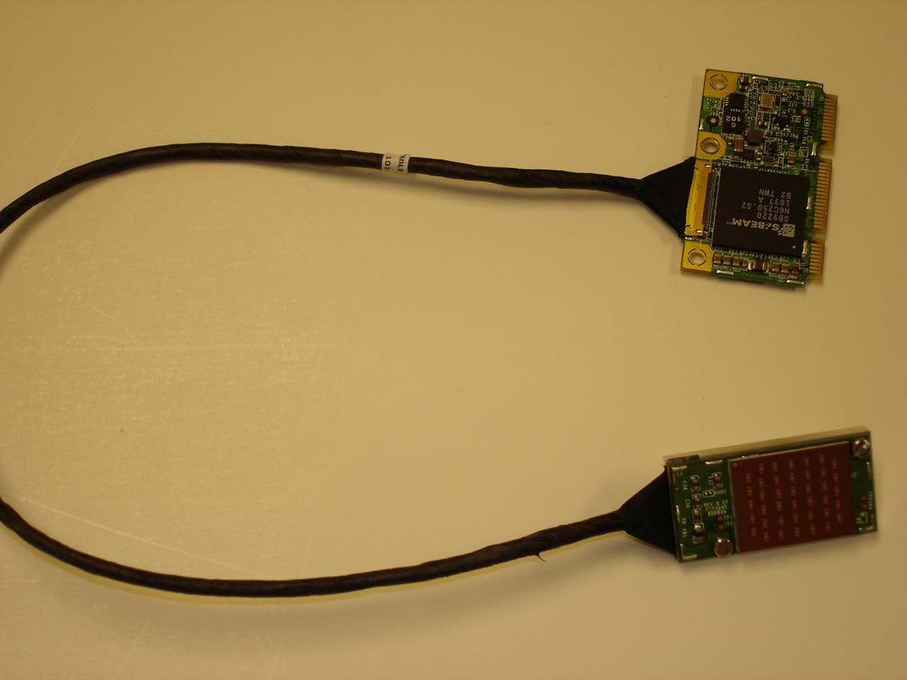
Click to zoom
Application Details
- Equipment Class
- DXX - Part 15 Low Power Communication Device Transmitter
- Date of Grant
- Nov 18, 2010
- Application Purpose
- Original Equipment
- Date of Application
- Nov 18, 2010
- Equipment Note
- 60GHz WirelessHD Display Mini Card Transmitter
- Frequency Range
- 60480.00000000 - 62640.00000000
- Country
- United States
Documents & Files
Document Text
Text extracted from the exhibit documents filed with the FCC. Open a document above to read the original.
Users Manual
November 2010 SiBEAM, Inc. SB-UG-0004-B 1 SK9210TX-HS Wireless HD Module OEM Installation Guide November 2010 SiBEAM, Inc. SB-UG-0004-B 2 Table of Contents Table of Contents _______________________________________________________ 2 Purpose of this Document ________________________________________________ 4 Introduction ___________________________________________________________ 4 Terminology _______________________________________________________________ 4 Getting Started _________________________________________________________ 6 SK9210TX-HS Contents______________________________________________________ 6 Unpacking the Module _______________________________________________________ 6 Customer Supplied Equipment ________________________________________________ 6 Setup _________________________________________________________________ 8 WirelessHD Applications Controller (WAC) ________________________________ 10 Appendix A: Specifications ______________________________________________ 13 Appendix B: Interference Statement _______________________________________ 14 Revision History _______________________________________________________ 15 November 2010 SiBEAM, Inc. SB-UG-0004-B 3 List of Figures Figure 1. SK9210TX-HS Module .................................................................................................................. 6 Figure 2. DisplayMini Card............................................................................................................................ 9 Figure 3. RF Board ......................................................................................................................................... 9 Figure 4. WAC Status Screen....................................................................................................................... 10 Figure 5. WAC Network Screen................................................................................................................... 11 Figure 6. WAC Info Screen.......................................................................................................................... 11 Figure 7. WAC Advanced Screen ................................................................................................................ 12 November 2010 SiBEAM, Inc. SB-UG-0004-B 4 Purpose of this Document This document provides customers with all the information necessary to allow them to utilize SiBEAM’s SK9210TX-HS WirelessHD module. It takes the user through an explanation of the system components, operation and bring-up while also describing the basic system configuration and diagnostics. It is expected that user of the SK9210TX-HS have some basic knowledge of the WirelessHD (WiHD) specification. If not, the user should review the major operation points of the specification to better understand the operation of the module. Introduction The SK9210TX-HS module provides a complete WiHD solution. The module is meant to be placed inside a Notebook PC’s DisplayMini Card (DMC) socket. Alternatively, the SK9210TX-HS may be placed into a DMC adapter board provided by SiBEAM (SK9200DMCA). The setup of the SK9210TX-HS is simple. Inserting the DMC board into the DMC socket and then properly placing the RF module in position followed by powering up the PC. A software applications tool, the WirelessHD Applications Controller (WAC), is provided to control the module in the PC. Terminology The following terms are used thru out this document. Audio Video Control (AVC) – the command structure defined in the WiHD specification used between WiHD stations and coordinator. Consumer Electronics Control bus (CEC) – the control bus defined in the HDMI specification which is used to pass command and other information between HDMI connected devices. DMCA (DisplyMini Card Adapter) Board – a reference adapter board with USB and HDMI inputs which are provided to a DMC socket on board. An SK9210TX-HS can be plugged into this socket and the adapter board may be plugged into any PC with USB and HDMI outputs to create a functioning solution. Embedded CPU – the 32-bit embedded CPU inside the SB9220 or SB9221 that runs all the WiHD protocol management between a source and sink device. Host Microcontroller – the Atmel AT91SAM7S series microcontroller on the HDMI Interface board which provides over control of the WiHD board and standalone operation. In development, the majority of the code running in this microcontroller will be ported to the host processor which runs the system. Line of Sight (LOS) - uninterrupted or blocked transmission from the WiHD Transmitter Module to the WiHD Receiver Module. Non Line of Sight (NLOS) - a transmission from the WiHD Transmitter Module which is not LOS and travels by bouncing off one or more objects before reaching the WiHD Receiver Module. SBAM2 – SiBEAM’s Application Manager tool for the PC to monitor status, set configuration and control other parameters of the WiHD Transmitter and Receiver Modules. SBAM2 is used for the second generation SK9200 kits. November 2010 SiBEAM, Inc. SB-UG-0004-B 5 Sink – a system which receives and renders A/V from a source device. This typically is a DTV or similar device. The WiHD Receiver Module can be considered a wireless A/V sink when it is connected to another A/V sink over HDMI. Sink devices may be a video sink, audio sink or audio/video (A/V) sink. SK9210TX-HS – the WirelessHD module including the DMC board, cable and RF board. Full schematics, BOM and layout files are available. Source – a system providing A/V to a sink device. This may be a DVD player, Set Top Box or A/V signal generator. The WiHD Transmitter Module can be considered a wireless A/V source when it is connected to another A/V source over HDMI. Source devices may be a video sources, audio source or audio/video (A/V) source. The SK9210TX-HS is a source device. WAC (WirelessHD Applications Controller) – Application tool which runs on the PC to control and monitor the SK9210TX-HS in a Notebook PC…
Text truncated - open the document above for the full version.
Cover Letter(s)
Company: SiBEAM, Inc. FCC ID: UK2-SK9210TX-HS Request for transmitter modular approval Transmitter Module Characteristics Item Requirements EUT 1 Have its own RF shielding Device is equipped with metal shielding to cover RF section. Refer to external photos. 2 Have buffered modulation/data inputs (if such inputs are provided), All inputs to the module are buffered through logic or microprocessor inputs. 3 Have it own power supply regulation Internal 1.0V, 1.2V, 2.5V power regulators. Refer to Block diagram. 4 Meet the antenna requirements of Section 15.203 Antenna requirements met. Refer to antenna specification provided and test report. 5 Be tested in a stand-alone configuration, i.e., the antenna, AC or DC power and data input/output lines must be connected to the module but, the module must not be inside another case during testing Condition satisfied – Module tested in stand- alone configuration and is not inside another case during testing. 6 Be labeled with its own FCC ID number, and if the FCC ID is not visible when the module is installed inside another device, then the outside of the device into which the module is installed must also display a label referring to the enclosed module. Labelling requirements met – see photos. 7 The modular transmitter is manufactured so that the user cannot influence the operation of the transmitter that will operate outside of the scope of the regulations. Yes 8 Address compliance with the Commission's RF exposure limits in Sections 1.1310 and 2.1093. In addition, spread spectrum transmitters operating under Section 15.247 are required to address RF exposure compliance in accordance with Section 15.247(b)(4). See test report for maximum permissible exposure reported.
ID Label/Location Info
PROPOSED FCC & IC ID LABEL AND LOCATION Bottom of Module FCC /IC Label Location SiBEAM, Inc. Model: SK9210TX-HS FCC: UK2-SK9210TX-HS IC: 6705A-SK9210TX HS PROPOSED FCC & IC ID LABEL FOR HOST DEVICE This device contains Model: SK9210TX-HS FCC ID: UK2-SK9210TX-HS IC: 6705A-SK9210TX HS
RF Exposure Info
REPORT NO: 10U13482-1A1 DATE: NOVEMBER 18, 2010 FCC ID: UK2-SK9210TX-HS IC: 6705A-SK9210TXHS Page 56 of 72 COMPLIANCE CERTIFICATION SERVICES (UL CCS) FORM NO: CCSUP4701D 47173 BENICIA STREET, FREMONT, CA 94538, USA TEL: (510) 771-1000 FAX: (510) 661-0888 This report shall not be reproduced except in full, without the written approval of UL CCS. 8. RF EXPOSURE 8.1. RULES AND LIMITS FCC RULES §1.1310 The criteria listed in Table 1 shall be used to evaluate the environmental impact of human exposure to radio-frequency (RF) radiation as specified in §1.1307(b), except in the case of portable devices which shall be evaluated according to the provisions of §2.1093 of this chapter. REPORT NO: 10U13482-1A1 DATE: NOVEMBER 18, 2010 FCC ID: UK2-SK9210TX-HS IC: 6705A-SK9210TXHS Page 57 of 72 COMPLIANCE CERTIFICATION SERVICES (UL CCS) FORM NO: CCSUP4701D 47173 BENICIA STREET, FREMONT, CA 94538, USA TEL: (510) 771-1000 FAX: (510) 661-0888 This report shall not be reproduced except in full, without the written approval of UL CCS. IC RULES IC Safety Code 6, Section 2.2.1 (a) A person other than an RF and microwave exposed worker shall not be exposed to electromagnetic radiation in a frequency band listed in Column 1 of Table 5, if the field strength exceeds the value given in Column 2 or 3 of Table 5, when averaged spatially and over time, or if the power density exceeds the value given in Column 4 of Table 5, when averaged spatially and over time. REPORT NO: 10U13482-1A1 DATE: NOVEMBER 18, 2010 FCC ID: UK2-SK9210TX-HS IC: 6705A-SK9210TXHS Page 58 of 72 COMPLIANCE CERTIFICATION SERVICES (UL CCS) FORM NO: CCSUP4701D 47173 BENICIA STREET, FREMONT, CA 94538, USA TEL: (510) 771-1000 FAX: (510) 661-0888 This report shall not be reproduced except in full, without the written approval of UL CCS. 8.2. OPERATING MODES The setup phase (LRP) and normal operation (HRP) do not occur simultaneously; therefore it is appropriate to consider the RF exposure during these two operating modes independently. 8.3. SETUP PHASE (LRP) RESULTS The Setup Phase (LRP) is a pulsed emission therefore source-based time-averaging is applicable. Referring to the plots below, the duty cycle of the Setup Phase emission is 100 % * (126 us) / (20.7 ms) = 0.61 % The orientation of the scanning LRP transmission is unconstrained, therefore the main lobe can be directed toward a person. The RF Exposure analysis is made using the peak gain and the source based time average power. Equations for the Near Field, Transition Field and/or Far Field Regions, as defined by OET 65 and as applicable to the evaluation distance, are used. FreqPeakPeakDutyAverage Peak Average EIRPEIRPCycleEIRPGainPower (GHz)(dBm)(mW)(% )(mW)(dBi)(mW) 60.3229.1812.80.614.95816.00.125 62.6427.4549.50.613.35216.00.084 REPORT NO: 10U13482-1A1 DATE: NOVEMBER 18, 2010 FCC ID: UK2-SK9210TX-HS IC: 6705A-SK9210TXHS Page 59 of 72 COMPLIANCE CERTIFICATION SERVICES (UL CCS) FORM NO: CCSUP4701D 47173 BENICIA STREET, FREMONT, CA 94538, USA TEL: (510) 771-1000 FAX: (510) 661-0888 This report shall not be reproduced except in full, without the written approval of UL CCS. DUTY CYCLE Note: Pulse width measurement has limited resolution in 5 ms/Div scan. REPORT NO: 10U13482-1A1 DATE: NOVEMBER 18, 2010 FCC ID: UK2-SK9210TX-HS IC: 6705A-SK9210TXHS Page 60 of 72 COMPLIANCE CERTIFICATION SERVICES (UL CCS) FORM NO: CCSUP4701D 47173 BENICIA STREET, FREMONT, CA 94538, USA TEL: (510) 771-1000 FAX: (510) 661-0888 This report shall not be reproduced except in full, without the written approval of UL CCS. FAR FIELD BOUNDARY CALCULATIONS The far-field boundary is given by OET 65 Equation 16 as: R far field = (0.6 * L^2) / λ where: L = Largest Antenna Dimension λ = Wavelength The Mobile evaluation distance is in the far field region for all frequencies. For 60.32 GHz the Portable evaluation distance is also in the far field region. For 62.64 GHz the Portable evaluation distance is less than the far field region boundary distance. FAR FIELD RF EXPOSURE EVALUATION For far-field distances EIRP is converted to Power Density using OET 65 Equation 18: S = EIRP / (4 * Pi * D S ^2) where: D S = Separation Distance FreqAverageSeparationPowerFCCPowerIC EIRPDistanceDensityLimitDensityLimit (GHz)(mW)(cm)(mW/cm^2)(mW/cm^2) (W/m^2) (W/m^2) Mobile Evaluation Distance 60.324.958200.00098710.01010 62.643.352200.00066710.00710 Portable Evaluation Distance 60.324.95850.01579010.15810 FrequencyLLambdaR (Far Field) (GHz)(cm)(cm)(cm) 60.322.00.4974.826 62.642.00.4795.011 REPORT NO: 10U13482-1A1 DATE: NOVEMBER 18, 2010 FCC ID: UK2-SK9210TX-HS IC: 6705A-SK9210TXHS Page 61 of 72 COMPLIANCE CERTIFICATION SERVICES (UL CCS) FORM NO: CCSUP4701D 47173 BENICIA STREET, FREMONT, CA 94538, USA TEL: (510) 771-1000 FAX: (510) 661-0888 This report shall not be reproduced except in full, without the written approval of UL CCS. NEAR FIELD BOUNDARY CALCULATIONS The near-field boundary is given by OET 65 Equation 12 as: R near field = (L^2) / (4 * λ) where: L = Largest Antenna Dimension λ = Wavelength For 62.64 GHz the Portable evaluation distance is greater than the near field region boundary distance and less than the far field region boundary, therefore transition field region equations are applicable. TRANSITION FIELD RF EXPOSURE EVALUATION Aperture efficiency is given by OET 65 Equation 14 as: η= (G * (λ^2) / (4 * Pi)) / ((Pi * (L^2) / 4) where: G = Power gain of antenna L = Largest Antenna Dimension λ = Wavelength FrequencyLLambdaR (Near Field) (GHz)(cm)(cm)(cm) 62.642.00.4792.088 FreqGainGainLambdaLAperture Efficiency (GHz ) (dBi) (linear)(cm)(cm)(linear) 62.6416.039.80.4792.00.232 REPORT NO: 10U13482-1A1 DATE: NOVEMBER 18, 2010 FCC ID: UK2-SK9210TX-HS IC: 6705A-SK9210TXHS Page 62 of 72 COMPLIANCE CERTIFICATION SERVICES (UL CCS) FORM NO: CCSUP4701D 47173 BENICIA STREET, FREMONT, CA 94538, USA TEL: (510) 771-1000 FAX: (510) 661-0888 This report shall not be reproduced except in full, without the written approval of UL CCS. The maximum value…
Text truncated - open the document above for the full version.
Test Report
FCC CFR47 PART 15 SUBPART C INDUSTRY CANADA RSS-210 ISSUE 7 CERTIFICATION TEST REPORT FOR 60GHz WirelessHD Display Mini Card Transmitter MODEL NUMBER: SK9210TX-HS FCC ID: UK2-SK9210TX-HS IC: 6705A-SK9210TXHS REPORT NUMBER: 10U13482-1, Revision A1 ISSUE DATE: NOVEMBER 18, 2010 Prepared for SIBEAM WIRELESS 555 NORTH MATHILDA AVE SUNNYVALE CA, 94085, U.S.A. Prepared by COMPLIANCE CERTIFICATION SERVICES (UL CCS) 47173 BENICIA STREET FREMONT, CA 94538, U.S.A. TEL: (510) 771-1000 FAX: (510) 661-0888 REPORT NO: 10U13482-1A1 DATE: NOVEMBER 18, 2010 FCC ID: UK2-SK9210TX-HS IC: 6705A-SK9210TXHS Page 2 of 72 COMPLIANCE CERTIFICATION SERVICES (UL CCS) FORM NO: CCSUP4701D 47173 BENICIA STREET, FREMONT, CA 94538, USA TEL: (510) 771-1000 FAX: (510) 661-0888 This report shall not be reproduced except in full, without the written approval of UL CCS. Revision History Rev. Issue Date Revisions Revised By -- 11/3/2010 Initial Issue M. Heckrotte A 11/18/2010 Revised MPE Calculations M. Heckrotte A1 11/18/2010 Revised section 8.4 description M. Heckrotte REPORT NO: 10U13482-1A1 DATE: NOVEMBER 18, 2010 FCC ID: UK2-SK9210TX-HS IC: 6705A-SK9210TXHS Page 3 of 72 COMPLIANCE CERTIFICATION SERVICES (UL CCS) FORM NO: CCSUP4701D 47173 BENICIA STREET, FREMONT, CA 94538, USA TEL: (510) 771-1000 FAX: (510) 661-0888 This report shall not be reproduced except in full, without the written approval of UL CCS. TABLE OF CONTENTS 1. ATTESTATION OF TEST RESULTS .................................................................................... 5 2. TEST METHODOLOGY ........................................................................................................ 6 3. FACILITIES AND ACCREDITATION .................................................................................... 6 4. CALIBRATION AND UNCERTAINTY .................................................................................. 6 4.1. MEASURING INSTRUMENT CALIBRATION ............................................................... 6 4.2. MEASUREMENT UNCERTAINTY ................................................................................ 6 5. EQUIPMENT UNDER TEST ................................................................................................. 7 5.1. DESCRIPTION OF EUT ................................................................................................ 7 5.2. OUTPUT POWER ......................................................................................................... 7 5.3. WORST-CASE CONFIGURATION AND MODE .......................................................... 7 5.4. DESCRIPTION OF TEST SETUP ................................................................................. 8 6. TEST AND MEASUREMENT EQUIPMENT ....................................................................... 10 7. APPLICABLE LIMITS AND TEST RESULTS .................................................................... 11 7.1. 6 dB BANDWIDTH ...................................................................................................... 11 7.1.1. Results for HRP Channel 2 (Low) and associated LRP Channels ...................... 11 7.1.2. Results for HRP Channel 3 (High) and associated LRP Channels ..................... 15 7.2. 99% and 26 dB BANDWIDTH ..................................................................................... 19 7.2.1. Results for HRP Channel 2 (Low) and associated LRP ...................................... 19 7.3. POWER DENSITY ...................................................................................................... 27 7.3.1. Results for HRP Channel 2 (Low) and associated LRP ...................................... 29 7.3.2. Results for HRP Channel 3 (High) and associated LRP ..................................... 34 7.4. PEAK OUTPUT POWER ............................................................................................ 39 7.4.1. Results for HRP Channel 2 (Low) and associated LRP ...................................... 40 7.4.2. Results for HRP Channel 3 (High) and associated LRP ..................................... 41 7.5. AVERAGE OUTPUT POWER ..................................................................................... 42 7.6. SPURIOUS EMISSIONS ............................................................................................. 43 7.7. RECEIVER SPURIOUS EMISSIONS ......................................................................... 49 7.8. AC MAINS LINE CONDUCTED EMISSIONS ............................................................. 49 7.9. FREQUENCY STABILITY ........................................................................................... 53 7.10. GROUP INSTALLATION ............................................................................................. 54 7.11. TRANSMITTER IDENTIFICATION ............................................................................. 55 8. RF EXPOSURE ................................................................................................................... 56 8.1. RULES AND LIMITS ................................................................................................... 56 8.2. OPERATING MODES ................................................................................................. 58 REPORT NO: 10U13482-1A1 DATE: NOVEMBER 18, 2010 FCC ID: UK2-SK9210TX-HS IC: 6705A-SK9210TXHS Page 4 of 72 COMPLIANCE CERTIFICATION SERVICES (UL CCS) FORM NO: CCSUP4701D 47173 BENICIA STREET, FREMONT, CA 94538, USA TEL: (510) 771-1000 FAX: (510) 661-0888 This report shall not be reproduced except in full, without the written approval of UL CCS. 8.3. SETUP PHASE (LRP) RESULTS ............................................................................... 58 8.4. NORMAL OPERATION (HRP) RESULTS .................................................................. 63 9. SETUP PHOTOS ................................................................................................................. 68 REPORT NO: 10U13482-1A1 …
Text truncated - open the document above for the full version.
Test Setup Photos
REPORT NO: 10U13482-1A1 DATE: NOVEMBER 18, 2010 FCC ID: UK2-SK9210TX-HS IC: 6705A-SK9210TXHS Page 68 of 72 COMPLIANCE CERTIFICATION SERVICES (UL CCS) FORM NO: CCSUP4701D 47173 BENICIA STREET, FREMONT, CA 94538, USA TEL: (510) 771-1000 FAX: (510) 661-0888 This report shall not be reproduced except in full, without the written approval of UL CCS. 9. SETUP PHOTOS RADIATED MEASUREMENT SETUP FRONT VIEW REPORT NO: 10U13482-1A1 DATE: NOVEMBER 18, 2010 FCC ID: UK2-SK9210TX-HS IC: 6705A-SK9210TXHS Page 69 of 72 COMPLIANCE CERTIFICATION SERVICES (UL CCS) FORM NO: CCSUP4701D 47173 BENICIA STREET, FREMONT, CA 94538, USA TEL: (510) 771-1000 FAX: (510) 661-0888 This report shall not be reproduced except in full, without the written approval of UL CCS. BACK VIEW REPORT NO: 10U13482-1A1 DATE: NOVEMBER 18, 2010 FCC ID: UK2-SK9210TX-HS IC: 6705A-SK9210TXHS Page 70 of 72 COMPLIANCE CERTIFICATION SERVICES (UL CCS) FORM NO: CCSUP4701D 47173 BENICIA STREET, FREMONT, CA 94538, USA TEL: (510) 771-1000 FAX: (510) 661-0888 This report shall not be reproduced except in full, without the written approval of UL CCS. TEMPERATURE CHAMBER MEASUREMENT SETUP REPORT NO: 10U13482-1A1 DATE: NOVEMBER 18, 2010 FCC ID: UK2-SK9210TX-HS IC: 6705A-SK9210TXHS Page 71 of 72 COMPLIANCE CERTIFICATION SERVICES (UL CCS) FORM NO: CCSUP4701D 47173 BENICIA STREET, FREMONT, CA 94538, USA TEL: (510) 771-1000 FAX: (510) 661-0888 This report shall not be reproduced except in full, without the written approval of UL CCS. LINE CONDUCTED EMISSIONS SETUP FRONT VIEW REPORT NO: 10U13482-1A1 DATE: NOVEMBER 18, 2010 FCC ID: UK2-SK9210TX-HS IC: 6705A-SK9210TXHS Page 72 of 72 COMPLIANCE CERTIFICATION SERVICES (UL CCS) FORM NO: CCSUP4701D 47173 BENICIA STREET, FREMONT, CA 94538, USA TEL: (510) 771-1000 FAX: (510) 661-0888 This report shall not be reproduced except in full, without the written approval of UL CCS. END OF REPORT BACK VIEW
Contact Information
Applicant
Jim Tavacoli
Test Firm
Compliance Certification ServicesThu Chan
Technical Specifications
| # | Rule Parts | Frequency Range | Power Output |
|---|---|---|---|
| 2 | 15C | 60.48 GHz - 62.64 GHz | 25.10 mW |
Other Applications from Lattice Semiconductor Corporation
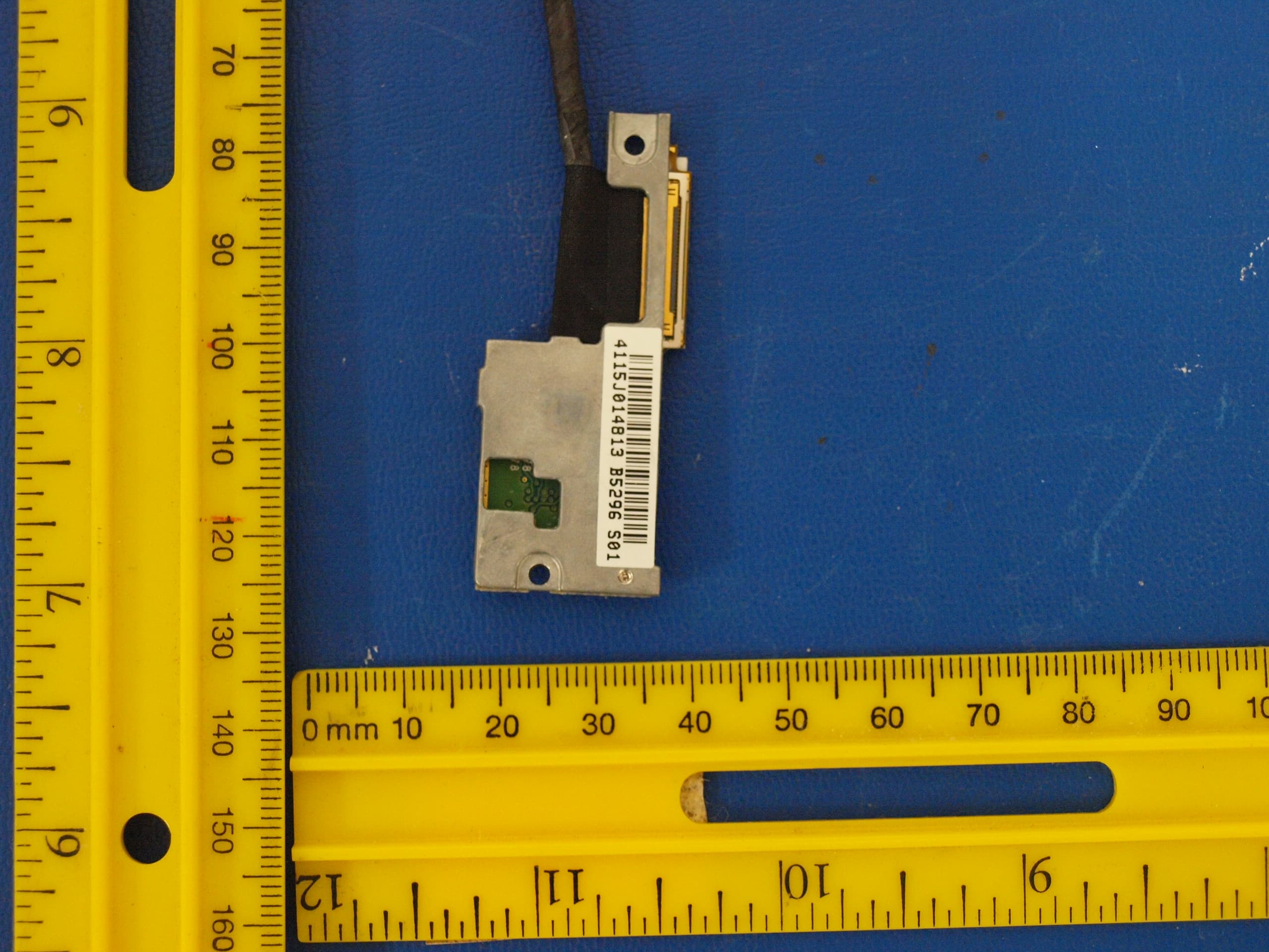
UK2-SIL-SK63100
Aug 14, 201360GHz WirelessHD Display Mini Card Transmitter
Equipment Class
DXX - Part 15 Low Power Communication Device Transmitter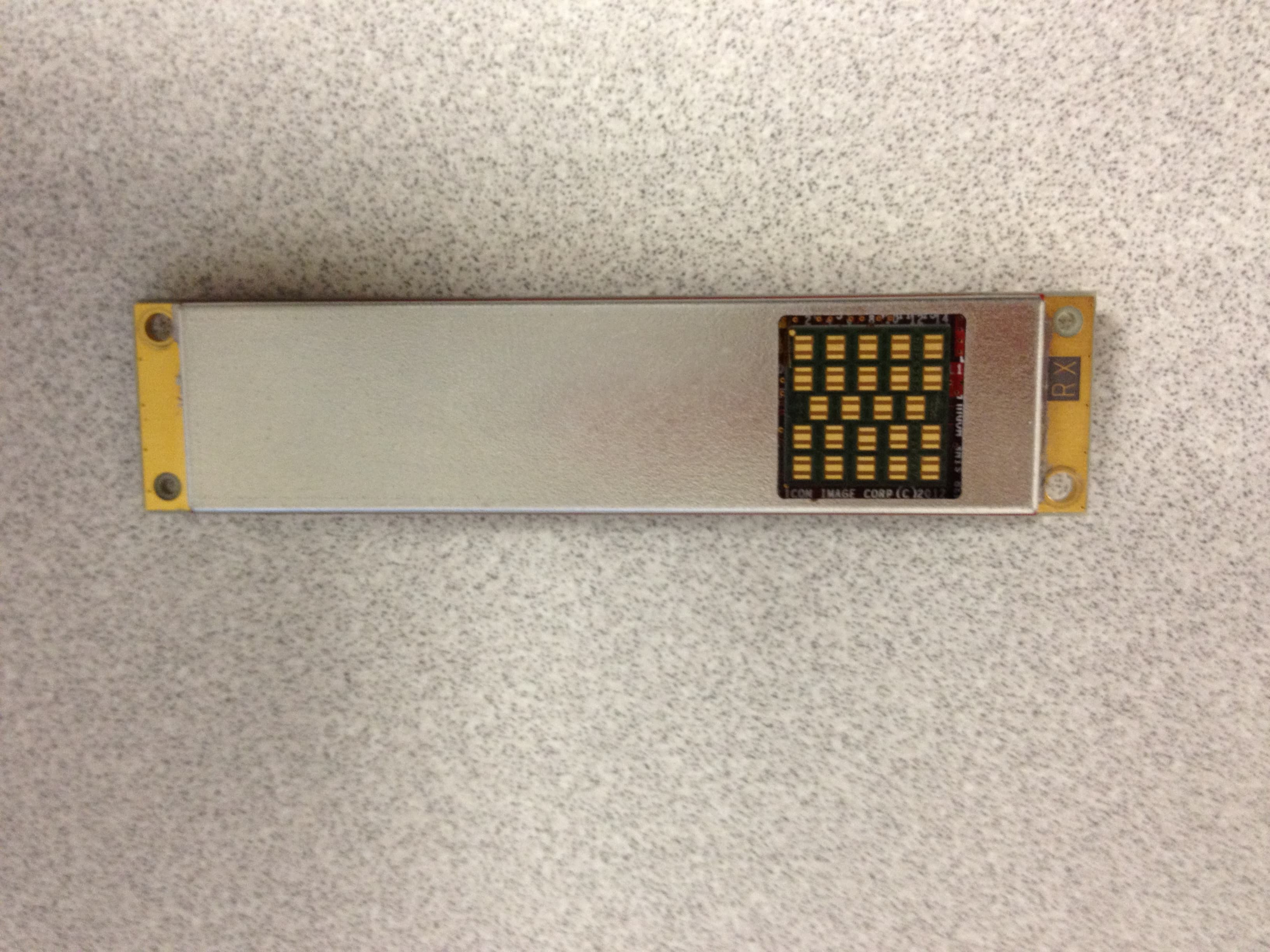
UK2-SII-SK63101
May 18, 2012wirelesshd receiver
Equipment Class
DXX - Part 15 Low Power Communication Device Transmitter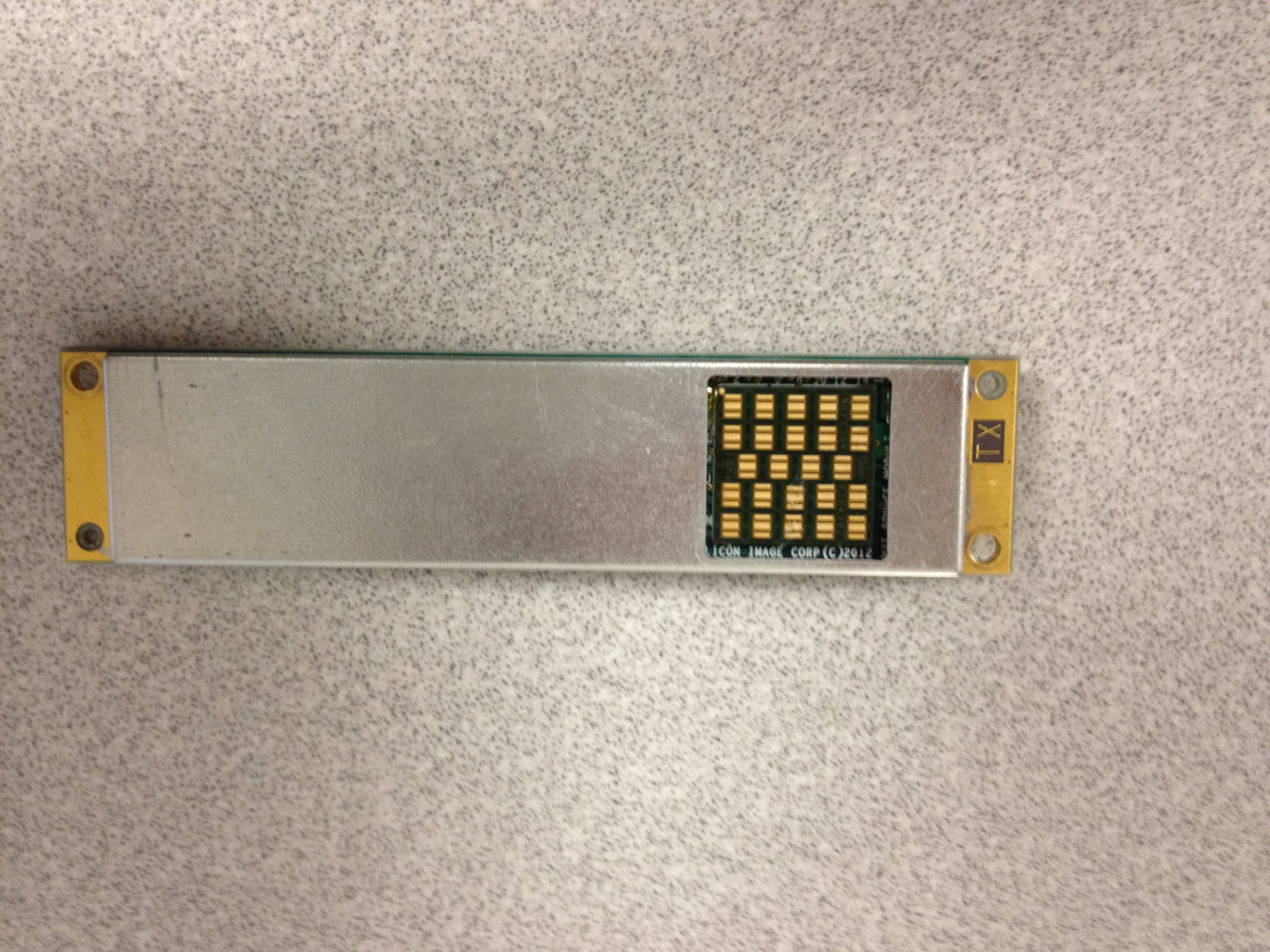
UK2-SII-SK63102
May 18, 2012wirelesshd transmitter
Equipment Class
DXX - Part 15 Low Power Communication Device Transmitter