UL9WNAP7325802.11 a/n Wireless Outdoor CPE
Planet Technology Corporation
Click to zoom
Application Details
- Equipment Class
- NII - Unlicensed National Information Infrastructure TX
- Date of Grant
- Jul 12, 2015
- Application Purpose
- Original Equipment
- Date of Application
- Jul 12, 2015
- Equipment Note
- 802.11 a/n Wireless Outdoor CPE
- Frequency Range
- 5755.00000000 - 5795.00000000
- Country
- Taiwan
Documents & Files
Document Text
Text extracted from the exhibit documents filed with the FCC. Open a document above to read the original.
Users Manual
Note – 1 –– 2 – – 3 –– 4 – 1. Package Contents 2. Installation Precautions 3. Physical Introduction – 7 –– 8 – – 5 –– 6 – The above steps introduce the simple installations and configurations of the WNAP-7325. For further configurations of different operation modes, please refer to the user manual which you can download from the website. http://www.planet.com.tw/en/support/download.php?type1=4& model=48590&type=3 If you have further questions, please contact the local dealer or distributor where you purchased this product. 2011-E10580-000 Thank you for choosing PLANET WNAP-7325. Before installing the AP, please verify the contents inside the package box. If there is any item missing or damaged, please contact the seller immediately. Connect the WNAP-7325 with your PC by an Ethernet cable plugging in LAN port of PoE injector in one side and in LAN port of PC in the other side. Power on the WNAP-7325 by PoE from PoE injector. 1. Click “Start” button located in the lower-left corner of your computer. 2. Click “Control Panel”. 3. Double-click “Network and Sharing Center” icon. 4. Click “Change Adapter Settings”. 5. Double-click “Local Area Connection”. 6. Select “Internet Protocol Version 4 (TCP/IPv4)” and click “Properties”. 7. Select “Use the following IP address”, and then click “OK” button twice to save the configuration. For example, as the default IP address of the WNAP-7325 is 192.168.1.253 and the router is 192.168.1.254, then you may choose from 192.168.1.1 to 192.168.1.252. Default IP Address: 192.168.1.253 Default Username: admin Default Password: admin Default SSID: WNAP-7325 STEP 1: The Web management allows you to access and manage the wireless AP easily. Launch the Web browser and enter the default IP address http://192.168.1.253. WNAP-7325 Quick Installation Guide 300Mbps 802.11a/n Wireless Outdoor CPE For security reasons, it is recommended to change the password at the first login and memorize it. STEP 2: When the login window pops up, please enter the User Name and Password. The default User Name and Password are both “admin”. Then click OK button to continue. STEP 3: After you enter into the Web User Interface, go to Operation Mode to configure your wireless network. Rear Panel Description – LED Indication Plastic Strap x 1 Quick Guide PoE Injector & Power Cord Signal IndicatorLAN 2 LED Power LEDLAN 1 LED STEP 1: Place the strap through the slot on the back of the WNAP-7325 and then around the pole. Tighten the strap to secure the WNAP-7325. 5. Pole Mounting Further Information: 6. Web Login IMPORTANT SAFETY PRECAUTIONS: 1) LIVES MAY BE AT RISK! Please be aware for the electric wires around, and tighten the pole. Carefully read the section "OUTDOOR INSTALLATION WARNING" in the manual before installation. 2) Users MUST use the “Power cord and PoE Injector” shipped in the box with the WNAP-7325. Otherwise, the product might be damaged. Caution WNAP-7325 STEP 2: Plug the power cord into the DC port and the other side into the AC socket. Then, plug the RJ45 cable (as shown in picture 4 under Step 1) into the POE port of the PoE injector. STEP 1: (A) Push the latch on the bottom of the WNAP-7325 to remove the sliding cover. Bottom Panel Description – Port 4. Hardware Installation 12 34 Grounding Terminal Reset Button LAN2PoE LAN (B) Plug the RJ45 Ethernet cable into the PoE LAN Port of the WNAP-7325. Then, slide back the cover of the WNAP-7325 to finish the installation. Ethernet Cable PoE Port Ethernet Cable PC 24V PoE Injector Data+Power Power Data LAN POE PoE Out Data In 1 2 1. Users MUST use a proper and well-installed surge arrestor and grounding wired with the WNAP-7325; otherwise, a sudden lightning could cause fatal damage to the WNAP-7325. EMD (Lightning) DAMAGE IS NOT COVERED UNDER WARRANTY. 2. Users MUST use the “Power cord and PoE Injector” shipped in the box with the WNAP-7325. Use of other options will cause damage to the WNAP-7325. Caution Note – 1 –– 2 – – 3 –– 4 – 1. Package Contents 2. Installation Precautions 3. Physical Introduction – 7 –– 8 – – 5 –– 6 – The above steps introduce the simple installations and configurations of the WNAP-7325. For further configurations of different operation modes, please refer to the user manual which you can download from the website. http://www.planet.com.tw/en/support/download.php?type1=4& model=48590&type=3 If you have further questions, please contact the local dealer or distributor where you purchased this product. 2011-E10580-000 Thank you for choosing PLANET WNAP-7325. Before installing the AP, please verify the contents inside the package box. If there is any item missing or damaged, please contact the seller immediately. Connect the WNAP-7325 with your PC by an Ethernet cable plugging in LAN port of PoE injector in one side and in LAN port of PC in the other side. Power on the WNAP-7325 by PoE from PoE injector. 1. Click “Start” button located in the lower-left corner of your computer. 2. Click “Control Panel”. 3. Double-click “Network and Sharing Center” icon. 4. Click “Change Adapter Settings”. 5. Double-click “Local Area Connection”. 6. Select “Internet Protocol Version 4 (TCP/IPv4)” and click “Properties”. 7. Select “Use the following IP address”, and then click “OK” button twice to save the configuration. For example, as the default IP address of the WNAP-7325 is 192.168.1.253 and the router is 192.168.1.254, then you may choose from 192.168.1.1 to 192.168.1.252. Default IP Address: 192.168.1.253 Default Username: admin Default Password: admin Default SSID: WNAP-7325 STEP 1: The Web management allows you to access and manage the wireless AP easily. Launch the Web browser and enter the default IP address http://192.168.1.253. WNAP-7325 Quick Installation Guide 300Mbps 802.11a/n Wireless Outdoor CPE For security reasons, it is recommended to change the password at the first login and memorize it. STEP 2: When the login window pops up, please enter the User Name and Password. The default User Name and Password ar…
Text truncated - open the document above for the full version.
External Photos
Registration number: W6D21409-14504-FCC FCC ID: UL9WNAP7325 Worldwide Testing Services (Taiwan) Co., Ltd. Appendix page 2 of 16 External Photos Registration number: W6D21409-14504-FCC FCC ID: UL9WNAP7325 Worldwide Testing Services (Taiwan) Co., Ltd. Appendix page 3 of 16 Registration number: W6D21409-14504-FCC FCC ID: UL9WNAP7325 Worldwide Testing Services (Taiwan) Co., Ltd. Appendix page 4 of 16 Registration number: W6D21409-14504-FCC FCC ID: UL9WNAP7325 Worldwide Testing Services (Taiwan) Co., Ltd. Appendix page 5 of 16 Registration number: W6D21409-14504-FCC FCC ID: UL9WNAP7325 Worldwide Testing Services (Taiwan) Co., Ltd. Appendix page 6 of 16 Registration number: W6D21409-14504-FCC FCC ID: UL9WNAP7325 Worldwide Testing Services (Taiwan) Co., Ltd. Appendix page 7 of 16 Registration number: W6D21409-14504-FCC FCC ID: UL9WNAP7325 Worldwide Testing Services (Taiwan) Co., Ltd. Appendix page 8 of 16 Registration number: W6D21409-14504-FCC FCC ID: UL9WNAP7325 Worldwide Testing Services (Taiwan) Co., Ltd. Appendix page 9 of 16
Test Report
of Applicant: PLANET Technology Corp. Address: 10F., No.96, Minquan Rd., Xindian Dist., New Taipei City 231, Taiwan (R.O.C.) Tested and Prepared by Worldwide Testing Services (Taiwan) Co., Ltd. FCC Registration No.: 930600 Industry Canada filed test laboratory Reg. No. IC 5679A-1 A2LA Accredited No.: 2732.01 Report No.: W6D21409-14504-C-1 6F, NO. 58, LANE 188, RUEY-KUANG RD., NEIHU TAIPEI 114, TAIWAN, R.O.C. TEL: 886-2-66068877 FAX: 886-2-66068879 E-mail: [email protected] FCC PART 15 SUBPART C TEST REPORT for 802.11a/n Wireless Outdoor CPE Model No.: WNAP-7325 FCC ID: UL9WNAP7325 Registration number: W6D21409-14504-C-1 FCC ID: UL9WNAP7325 Worldwide Testing Services(Taiwan) Co., Ltd. Page 1 of 63 TABLE OF CONTENTS 1 GENERAL INFORMATION ..........................................................................................................2 1.1 N OTES..........................................................................................................................................2 1.2 TESTING LABORATORY................................................................................................................3 1.2.1 Location ..............................................................................................................................3 1.2.2 Details of accreditation status ............................................................................................3 1.3 DETAILS OF APPROVAL HOLDER...................................................................................................3 1.4 A PPLICATION DETAILS.................................................................................................................4 1.5 G ENERAL INFORMATION OF TEST ITEM........................................................................................4 1.6 T EST STANDARDS.........................................................................................................................6 2 TECHNICAL TEST..........................................................................................................................7 2.1 S UMMARY OF TEST RESULTS........................................................................................................7 2.2 T EST ENVIRONMENT....................................................................................................................7 2.3 TEST EQUIPMENT LIST....................................................................................................................8 2.4 GENERAL TEST PROCEDURE......................................................................................................10 3 TEST RESULTS (ENCLOSURE) ................................................................................................12 3.1 P EAK OUTPUT POWER (TRANSMITTER) ......................................................................................13 3.2 EQUIVALENT ISOTROPIC RADIATED POWER................................................................................22 3.3 RF EXPOSURE COMPLIANCE REQUIREMENTS............................................................................22 3.3.1 MPE CALCULATION METHOD...................................................................................................22 3.4 TRANSMITTER RADIATED EMISSIONS IN RESTRICTED BANDS....................................................24 3.5 S PURIOUS EMISSIONS (TX) .........................................................................................................25 3.6 RADIATED EMISSION ON THE BAND EDGE..................................................................................34 3.7 MINIMUM 6 DB BANDWIDTH.....................................................................................................41 3.8 P EAK POWER SPECTRAL DENSITY.............................................................................................50 3.9 RADIATED EMISSION FROM DIGITAL PART................................................................................59 3.10 P OWER LINE CONDUCTED EMISSION....................................................................60 A PPENDIX..............................................................................................................................................63 Registration num ber: W6D21409-14504-C-1 FCC ID: UL9WNAP7325 Worldwide Testing Services(Taiwan) Co., Ltd. Page 2 of 63 1 General Information 1.1 Notes The purpose of conformity testing is to increase the probability of adherence to the essential requirements or conformity specifications, as appropriate. The complexity of the technical specifications, however, means that full and thorough testing is impractical for both technical and economic reasons. Furthermore, there is no guarantee that a test sample which has passed all the relevant tests conforms to a specification. Neither is there any guarantee that such a test sample will interwork with other genuinely open systems. The existence of the tests nevertheless provides the confidence that the test sample possesses the qualities as maintained and that is performance generally conforms to representative cases of communications equipment. The test results of this test report relate exclusively to the item tested as specified in 1.5. The test report may only be reproduced or published in full. Reproduction or publication of extracts from the report requires the prior written approval of the Worldwide Testing Services(Taiwan) Co., Ltd. Specific Conditions: Usage of the hereunder tested device in combination with other integrated or external antennas requires at least additional output power measurements, spurious emission measurements, conducted emission measurements (AC supply lines) and radio frequency exposure evaluations for each individual configuration performed, for certification by FCC. The test sample is able to work according IEEE 802.11 a/n. This report is related to FCC Part 15 C (OFDM device). Tester: Jan uary 14, 2015 Spencer Yang DateWTS-La…
Text truncated - open the document above for the full version.
Test Setup Photos
Registration number: W6D21409-14504-FCC FCC ID: UL9WNAP7325 Worldwide Testing Services (Taiwan) Co., Ltd. Appendix page 14 of 16 Set Up Photo of Radiated Emission Below 1GHz Registration number: W6D21409-14504-FCC FCC ID: UL9WNAP7325 Worldwide Testing Services (Taiwan) Co., Ltd. Appendix page 15 of 16 Registration number: W6D21409-14504-FCC FCC ID: UL9WNAP7325 Worldwide Testing Services (Taiwan) Co., Ltd. Appendix page 16 of 16 Set Up Photo of Conducted Emission
Contact Information
Applicant
Tom Shih(Product Manager)
Technical Contact
Worldwide Testing Services (Taiwan) Co., Ltd.Danny Sung
[email protected]+886-2-6606-8877
6F., No. 58, Lane 188, Ruey Kuand Rd. · Taipei · Taiwan
Test Firm
Worldwide Testing Services (Taiwan) Co., Ltd.Rex Kao
Technical Specifications
| # | Rule Parts | Frequency Range | Power Output |
|---|---|---|---|
| 2 | 15E | 5.75 GHz - 5.79 GHz | 641.21 mW |
Other Applications from Planet Technology Corporation
UL9WNAP6315
Aug 03, 2015802.11n Wireless Outdoor CPE
Equipment Class
DTS - Digital Transmission System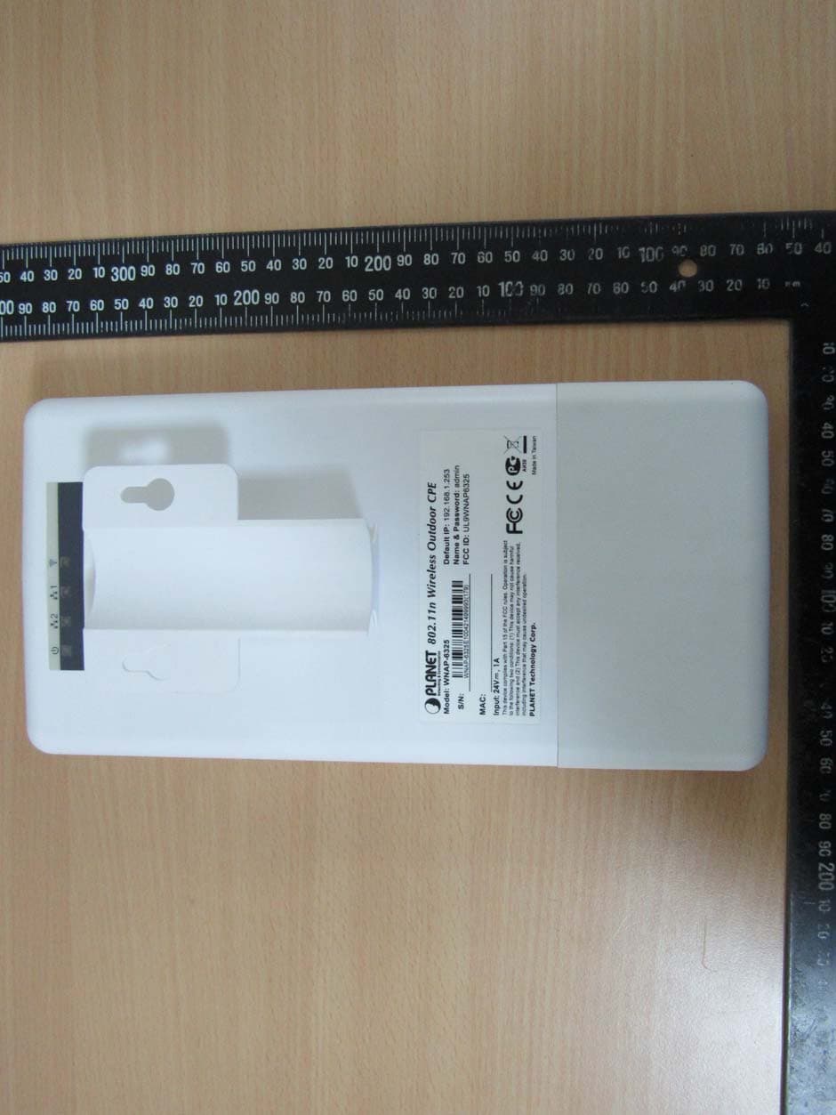
UL9WNAP6325
Jul 12, 2015802.11n Wireless Outdoor CPE
Equipment Class
DTS - Digital Transmission System
UL9-WDAPC7200AC
Dec 17, 20141200Mbps 802.11ac Dual Band Ceiling Mount Wireless Access Point
Equipment Class
DTS - Digital Transmission System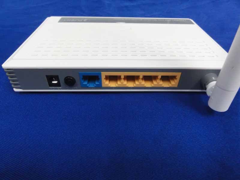
UL9WNRT617V2
Jul 21, 2013150Mbps 802.11n Wireless Broadband Router
Equipment Class
DTS - Digital Transmission System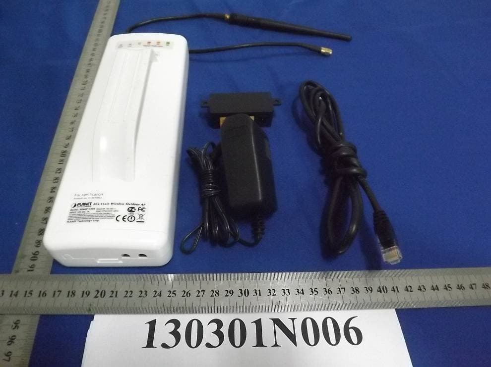
UL9WNAP7206
Jun 09, 2013802.11a/n Wireless Outdoor AP
Equipment Class
DTS - Digital Transmission System