UNH-MXP802NPCMWireless-N Notebook Adapter
Newer Technology, Inc.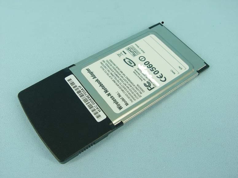
Click to zoom
Application Details
- Equipment Class
- DTS - Digital Transmission System
- Date of Grant
- Dec 06, 2007
- Application Purpose
- Original Equipment
- Date of Application
- Dec 05, 2007
- Equipment Note
- Wireless-N Notebook Adapter
- Frequency Range
- 2412.00000000 - 2462.00000000
- Company
- Newer Technology, Inc.
- Country
- United States
Documents & Files
Document Text
Text extracted from the exhibit documents filed with the FCC. Open a document above to read the original.
Users Manual
Wireless–N Client Adapter Quick Installation Guide Version 2.2 1 Table of Contents English WLAN Adapter Quick installation Guide ................................................................................................ 2 Utility and Driver Installation.................................................................................................................. 2 Hardware Installation ............................................................................................................................ 4 Wireless Network Setup........................................................................................................................ 5 WPS Function ....................................................................................................................................... 6 2 Copyright statement No part of this publication may be reproduced, stored in a retrieval system, or transmitted in any form or by any means, whether electronic, mechanical, photocopying, recording, or otherwise without the prior writing of the publisher. JULY 2007 WLAN Adapter Quick installation Guide Utility and Driver Installation 1. Turn “On” your computer. Insert the Driver CD then wait for the Autorun prompt like below. 2. If Autorun does not work, please browse the CD content and double click the “ Autorun.exe ”. 3. Click the model name which you had bought. 4. Click “Next” and then follow the instructions on the screen to continue the installation. Note: Ne pas insérer l'Adaptateur WLAN dans votre ordinateur avant d'avoir fini l'installation de l'Utilitaire et du Pilote. 3 5. Click the Finish button in this screen; both the driver and the Configuration Utility are installed on your computer. 4 Hardware Installation For PCMCIA or USB adapters, simply insert or connect the adapter after running the setup file. For PCI cards, you must shut down the computer, plug the card in an available PCI slot, and restart the operating system. After the computer boots back up, it will detect the wireless card and then start the New Hardware Found wizard. Respond to the prompts displayed by the wizard, and select the option, “Install the software automatically (Recommended) ”; the operating system will find the driver automatically. You can launch the Configuration Utility by clicking the left mouse button on the Configuration Utility icon and selecting Advanced Configuration. If the Configuration Utility icon is not displayed in the System Tray, you can restart the Configuration Utility from the Start Menu by selecting Programs and Wireless Network Utility Configuration. The Configuration Utility consists of window with four tabs: Link Information, AP List, Profile Setting, and About. Please find information about these tabs in the User’s Guide (from the CD contents, select Manual & QIG that shown with PDF format.) 5 Wireless Network Setup 1. Peer-to-Peer: Connects with other wireless client(s). This does not require Access Point. Please make sure the “Network Name” (SSID or ESSID) and “Peer-to-Peer” channel are the same for all clients in the same wireless network. Double click on the Configuration Utility icon to open the utility. - Click on “Profile Setting” tab and “Add” to create a new profile. - Enter a name that the profile correspond, click “Next”. - Select the “Network Type”, click on the drop-down arrow and select “Peer-to-Peer”, and then at “Peer-to-Peer Channel”, use the up/down arrows to select the channel number, and then click “Next”. - Select the Authentication Mode to enable the “Encryption” if you have any security concern. Once you enable the encryption function, then you should input the corresponding key. Click “Next”. - On IP Setting select “Enable” or “Disable” to make used of it. Click “Complete” to finish the configuration. 2. Access Point: Connects to network via Access Point. - Click “AP List” tab. - Select the listed Wireless Network to Join. - Click “Connect” to join the network. * Note: You might need to configure a Profile before if the destination network had a “WEP KEY” protected. The equipment has been tested and found to comply with FCC and CE Rules.Operation is subject to the following two conditions: (1) This device may not cause harmful interference. (2) This device must accept any interference received including interference that may cause undesired operation. 6 WPS Function Wi-Fi Protected Setup (WPS) is a standard for easy and secure establishment of a wireless home network, created by the Wi-Fi Alliance. The goal of the WPS protocol is to simplify the process of connecting any home device to the wireless network. To secure your wireless network, you could push the “WPS” button under user interface as below: There are two ways to enable WPS connection: 1. PBC mode: Choose a Router in the list then click “PBC” button. 2. PIN mode: Choose a Router in the list and check the PIN codes are the same between Router and Client then click “PIN” button. 7 Federal Communication Commission Interference Statement This equipment has been tested and found to comply with the limits for a Class B digital device, pursuant to Part 15 of the FCC Rules. These limits are designed to provide reasonable protection against harmful interference in a residential installation. This equipment generates, uses and can radiate radio frequency energy and, if not installed and used in accordance with the instructions, may cause harmful interference to radio communications. However, there is no guarantee that interference will not occur in a particular installation. If this equipment does cause harmful interference to radio or television reception, which can be determined by turning the equipment off and on, the user is encouraged to try to correct the interference by one of the following measures: - Reorient or relocate the receiving antenna. - Increase the separation between the equipment and receiver. - Connect the equipment into an outlet on a circuit different from that to which…
Text truncated - open the document above for the full version.
External Photos
Page 1 CONSTRUCTION PHOTOS OF EUT Page 2
Internal Photos
Page 3 Page 4
Operational Description
FCC ID: UNH-MXP802NPCM Report No.: RF951121L11C Operational Description This device is a Wireless-N Notebook Adapter, which operates in the 2.4GHz frequency spectrum with throughput of up to 300Mbps which OFDM technique will be applied. If the signal to noise radio is too poor which could not support 300Mbps, the 11Mbps data rate with DSSS technique will be applied. The transmitter of the EUT is powered by host equipment. The antenna is Printed Dipole antenna without connector. The other instruction, please have a look at the users manual.
RF Exposure Info
Report No.: SA951121L11C 1 Report Format Version 2.0.6 Reference No.: 961112L03 SAR TEST REPORT REPORT NO.: SA951121L11C MODEL NO.: MXP802NPCM RECEIVED: Nov. 21, 2006 TESTED: Feb. 26, 2007 ISSUED: Nov. 13, 2007 APPLICANT: Newer Technology, Inc. ADDRESS: 1002 Courtaulds Drive, Woodstock, IL, United States, 60098 ISSUED BY: Advance Data Technology Corporation LAB ADDRESS: 47 14 th Lin, Chiapau Tsun, Linko, Taipei, Taiwan, R.O.C. TEST LOCATION: No. 19, Hwa Ya 2 nd Rd., Kueishan, Taoyuan, Taiwan, R.O.C. This test report consists of 41 pages in total except Appendix. It may be duplicated completely for legal use with the approval of the applicant. It should not be reproduced, except in full, without the written approval of our laboratory. The client should not use it to claim product endorsement by TAF, A2LA or any government agencies. The test results in the report only apply to the tested sample. Report No.: SA951121L11C 2 Report Format Version 2.0.6 Reference No.: 961112L03 TABLE OF CONTENTS 1. CERTIFICATION.................................................................................................................3 2. GENERAL INFORMATION..................................................................................................4 2.1 GENERAL DESCRIPTION OF EUT....................................................................................4 2.2 GENERAL DESCRIPTION OF APPLIED STANDARDS.......................................................5 2.3 GENERAL INOFRMATION OF THE SAR SYSTEM.............................................................7 2.4 GENERAL DESCRIPTION OF THE SPATIAL PEAK SAR EVALUATION...........................10 3. DESCRIPTION OF SUPPORT UNITS...............................................................................14 4. DESCRIPTION OF TEST MODES AND CONFIGURATIONS............................................15 4.1. DESCRIPTION OF ANTENNA LOCATION........................................................................15 4.2. DESCRIPTION OF ASSESSMENT POSITION..................................................................16 4.3. DESCRIPTION OF TEST MODE......................................................................................17 4.4. SUMMARY OF TEST RESULTS.......................................................................................18 5. TEST RESULTS................................................................................................................19 5.1 TEST PROCEDURES.......................................................................................................19 5.2 MEASURED SAR RESULTS.............................................................................................21 5.3 SAR LIMITS......................................................................................................................25 5.4 RECIPES FOR TISSUE SIMULATING LIQUIDS...............................................................26 5.5 TEST EQUIPMENT FOR TISSUE PROPERTY.................................................................28 6. SYSTEM VALIDATION......................................................................................................29 6.1 TEST EQUIPMENT...........................................................................................................29 6.2 TEST PROCEDURE.........................................................................................................30 6.3 VALIDATION RESULTS....................................................................................................32 6.4 SYSTEM VALIDATION UNCERTAINTIES.........................................................................33 7. MEASUREMENT SAR PROCEDURE UNCERTAINTIES..................................................34 7.1. PROBE CALIBRATION UNCERTAINTY...........................................................................34 7.2. ISOTROPY UNCERTAINTY.............................................................................................35 7.3. BOUNDARY EFFECT UNCERTAINTY.............................................................................35 7.4. PROBE LINEARITY UNCERTAINTY.................................................................................36 7.5. READOUT ELECTRONICS UNCERTAINTY.....................................................................36 7.6. RESPONSE TIME UNCERTAINTY...................................................................................36 7.7. INTEGRATION TIME UNCERTAINTY..............................................................................37 7.8. PROBE POSITIONER MECHANICAL TOLERANCE.........................................................38 7.9. PROBE POSITIONING.....................................................................................................38 7.10. PHANTOM UNCERTAINTY..............................................................................................39 7.11. DASY4 UNCERTAINTY BUDGET.....................................................................................40 8. INFORMATION ON THE TESTING LABORATORIES.......................................................41 APPENDIX A: TEST CONFIGURATIONS AND TEST DATA APPENDIX B: ADT SAR MEASUREMENT SYSTEM APPENDIX C: PHOTOGRAPHS OF SYSTEM VALIDATION APPENDIX D: SYSTEM CERTIFICATE & CALIBRATION Report No.: SA951121L11C 3 Report Format Version 2.0.6 Reference No.: 961112L03 1. CERTIFICATION PRODUCT: Wireless-N Notebook Adapter MODEL: MXP802NPCM BRAND: MaxPower APPLICANT: Newer Technology, Inc. TESTED: Feb. 26, 2007 TEST SAMPLE: ENGINEERING SAMPLE STANDARDS: FCC Part 2 (Section 2.1093), RSS-102 FCC OET Bulletin 65, Supplement C (01-01) The above equipment (model: MXP802NPCM) have been tested by Advance Data Technology Corporation, and found compliance with the requirement of the above standards. The test record, data evaluation & Equipment Under Test (EUT) configurations represented herein are true and accurate accounts of the measurements of the sample’s EMC characteristics unde…
Text truncated - open the document above for the full version.
Test Report
Report No.: RF951121L11C 1 Report Format Version 2.0.6 Reference No.: 961112L03 FCC TEST REPORT REPORT NO.: RF951121L11C MODEL NO.: MXP802NPCM RECEIVED: Nov. 21, 2006 TESTED: Jan. 23 ~ Feb. 13, 2007 ISSUED: Nov. 13, 2007 APPLICANT: Newer Technology, Inc. ADDRESS: 1002 Courtaulds Drive, Woodstock, IL, United States, 60098 ISSUED BY: Advance Data Technology Corporation LAB ADDRESS: 47 14 th Lin, Chiapau Tsun, Linko, Taipei, Taiwan, R.O.C. TEST LOCATION: No. 19, Hwa Ya 2 nd Rd., Kueishan, Taoyuan, Taiwan, R.O.C. This test report consists of 104 pages in total. It may be duplicated completely for legal use with the approval of the applicant. It should not be reproduced, except in full, without the written approval of our laboratory. The client should not use it to claim product endorsement by TAF, A2LA or any government agencies. The test results in the report only apply to the tested sample. Report No.: RF951121L11C 2 Report Format Version 2.0.6 Reference No.: 961112L03 TABLE OF CONTENTS 1. CERTIFICATION ..................................................................................................................... 4 2. SUMMARY OF TEST RESULTS ............................................................................................ 5 2.1 MEASUREMENT UNCERTAINTY ......................................................................................... 5 3. GENERAL INFORMATION ..................................................................................................... 6 3.1 GENERAL DESCRIPTION OF EUT....................................................................................... 6 3.2 DESCRIPTION OF TEST MODES......................................................................................... 7 3.2.1 CONFIGURATION OF SYSTEM UNDER TEST.................................................................... 7 3.2.2 TEST MODE APPLICABILITY AND TESTED CHANNEL DETAIL ........................................ 8 3.3 GENERAL DESCRIPTION OF APPLIED STANDARDS...................................................... 10 3.4 DESCRIPTION OF SUPPORT UNITS................................................................................. 10 4. TEST TYPES AND RESULTS .............................................................................................. 11 4.1 CONDUCTED EMISSION MEASUREMENT....................................................................... 11 4.1.1 LIMITS OF CONDUCTED EMISSION MEASUREMENT.................................................... 11 4.1.2 TEST INSTRUMENTS .........................................................................................................11 4.1.3 TEST PROCEDURES ..........................................................................................................12 4.1.4 DEVIATION FROM TEST STANDARD ................................................................................ 12 4.1.5 TEST SETUP........................................................................................................................ 13 4.1.6 EUT OPERATING CONDITIONS ......................................................................................... 13 4.1.7 TEST RESULTS ................................................................................................................... 14 4.2 RADIATED EMISSION MEASUREMENT ............................................................................ 32 4.2.1 LIMITS OF RADIATED EMISSION MEASUREMENT ......................................................... 32 4.2.2 TEST INSTRUMENTS .........................................................................................................33 4.2.3 TEST PROCEDURES ..........................................................................................................34 4.2.4 DEVIATION FROM TEST STANDARD ................................................................................ 34 4.2.5 TEST SETUP........................................................................................................................ 35 4.2.6 EUT OPERATING CONDITIONS ......................................................................................... 35 4.2.7 TEST RESULTS ................................................................................................................... 36 4.3 6dB BANDWIDTH MEASUREMENT ................................................................................... 51 4.3.1 LIMITS OF 6dB BANDWIDTH MEASUREMENT................................................................. 51 4.3.2 TEST INSTRUMENTS .........................................................................................................51 4.3.3 TEST PROCEDURE............................................................................................................. 51 4.3.4 DEVIATION FROM TEST STANDARD ................................................................................ 51 4.3.5 TEST SETUP........................................................................................................................ 52 4.3.6 EUT OPERATING CONDITIONS ......................................................................................... 52 4.3.7 TEST RESULTS ................................................................................................................... 53 4.4 MAXIMUM PEAK OUTPUT POWER ................................................................................... 65 4.4.1 LIMITS OF MAXIMUM PEAK OUTPUT POWER MEASUREMENT ................................... 65 4.4.2 INSTRUMENTS.................................................................................................................... 65 4.4.3 TEST PROCEDURES ..........................................................................................................65 Report No.: RF951121L11C 3 Report Format Version 2.0.6 Reference No.: 961112L03 4.4.4 DEVIATION FROM TEST STANDARD ................................................................................ 65 4.4.5 TEST SE…
Text truncated - open the document above for the full version.
Test Report
Report No.: RF951121L11C 81 Report Format Version 2.0.6 Reference No.: 961112L03 FOR CHAIN 1: CH 1 CH 4 Report No.: RF951121L11C 82 Report Format Version 2.0.6 Reference No.: 961112L03 CH 7 Report No.: RF951121L11C 83 Report Format Version 2.0.6 Reference No.: 961112L03 4.6 BAND EDGES MEASUREMENT 4.6.1 LIMITS OF BAND EDGES MEASUREMENT Below –20dB of the highest emission level of operating band (in 100kHz Resolution Bandwidth). 4.6.2 TEST INSTRUMENTS For Single TX: DESCRIPTION & MANUFACTURER MODEL NO. SERIAL NO. CALIBRATED UNTIL R&S SPECTRUM ANALYZER FSP40 100040 Jun. 07, 2007 NOTE: The calibration interval of the above test instruments is 12 months and the calibrations are traceable to NML/ROC and NIST/USA. For Dual TX: DESCRIPTION & MANUFACTURER MODEL NO. SERIAL NO. CALIBRATED UNTIL Spectrum Analyzer FSP40 100269 Aug. 07, 2007 HORN Antenna BBHA 9120 D 9120D-563 Jul. 26, 2007 HORN Antenna BBHA 9170 BBHA9170242 Jan. 16, 2008 RF signal cable SUCOFLEX 104 218188/218189 Nov. 14, 2007 RF signal cable 8D-FB Cable-HYCH9-01 Mar. 08, 2007 Software ADT_Radiated_V7.6NA NA Antenna Tower 2070/2080 512.835.4684 NA Turn Table 2087-2.03 NA NA Antenna Tower &Turn Table Controller EMCO 2090 NA NA NOTE: The calibration interval of the above test instruments is 12 months and the calibrations are traceable to NML/ROC and NIST/USA. Report No.: RF951121L11C 84 Report Format Version 2.0.6 Reference No.: 961112L03 4.6.3 TEST PROCEDURE For Single TX: The transmitter output was connected to the spectrum analyzer via a low lose cable. Set both RBW and VBW of spectrum analyzer to 100kHz with suitable frequency span including 10Hz bandwidth from band edge. The band edges was measured and recorded. The spectrum plots (Peak RBW = VBW = 100kHz; Average RBW = 1MHz, VBW = 10Hz) are attached on the following pages. For Dual TX: a. The EUT was placed on the top of a rotating table 0.8 meters above the ground at a 3 meter semi-anechoic chamber. The table was rotated 360 degrees to determine the position of the highest radiation. b. The EUT was set 3 meters away from the interference-receiving antenna, which was mounted on the top of a variable-height antenna tower. c. The antenna is a broadband antenna, and its height is varied from one meter to four meters above the ground to determine the maximum value of the field strength. Both horizontal and vertical polarizations of the antenna are set to make the measurement. d. For each suspected emission, the EUT was arranged to its worst case and then the antenna was tuned to heights from 1 meter to 4 meters and the rotatable table was turned from 0 degrees to 360 degrees to find the maximum reading. e. Set both RBW and VBW of spectrum analyzer to 100kHz with suitable frequency span including 100MHz bandwidth from band edge. The band edges was measured and recorded. The spectrum plots (Peak RBW = VBW = 100kHz; Average RBW = 1MHz, VBW = 10Hz) NOTE: The resolution bandwidth of test receiver/spectrum analyzer is 1 MHz and the video bandwidth is 10Hz for Average detection (AV) at frequency above 1GHz. 4.6.4 DEVIATION FROM TEST STANDARD No deviation Report No.: RF951121L11C 85 Report Format Version 2.0.6 Reference No.: 961112L03 4.6.5 EUT OPERATING CONDITION Same as Item 4.3.6 4.6.6 TEST RESULTS The spectrum plots are attached on the following 24 images. D1 line indicates the highest level, and D2 line indicates the 20dB offset below D1. It shows compliance with the requirement in part 15.247(d). 802.11b DSSS MODULATION: NOTE 1: The band edge emission plot of DSSS technique on the next page shows 49.46dBc between carrier maximum power and local maximum emission in restrict band (2.386080000GHz). The emission of carrier strength list in the test result of channel 1 at the item 4.2.7 is 106.15dBuV/m (Peak), so the maximum field strength in restrict band is 106.15 – 49.46 = 56.69dBuV/m which is under 74dBuV/m limit. The band edge emission plot of DSSS technique on the next page shows 52.05dBc between carrier maximum power and local maximum emission in restrict band (2.386480000GHz). The emission of carrier strength list in the test result of channel 1 at the item 4.2.7 is 101.63dBuV/m (Average), so the maximum field strength in restrict band is 101.63 – 52.05 = 49.58dBuV/m which is under 54dBuV/m limit. NOTE 2: The band edge emission plot of DSSS technique on the next second page shows 50.36dBc between carrier maximum power and local maximum emission in restrict band (2.488060000GHz). The emission of carrier strength list in the test result of channel 11 at the item 4.2.7 is 106.36dBuV/m (Peak), so the maximum field strength in restrict band is 106.36 – 50.36= 56.00dBuV/m which is under 74dBuV/m limit. The band edge emission plot of DSSS technique on the next third page shows 53.69dBc between carrier maximum power and local maximum emission in restrict band (2.487660000GHz). The emission of carrier strength list in the test result of channel 11 at the item 4.2.7 is 102.00dBuV/m (Average), so the maximum field strength in restrict band is 102.00 – 53.69 = 48.31dBuV/m which is under 54dBuV/m limit. Report No.: RF951121L11C 86 Report Format Version 2.0.6 Reference No.: 961112L03 Report No.: RF951121L11C 87 Report Format Version 2.0.6 Reference No.: 961112L03 Report No.: RF951121L11C 88 Report Format Version 2.0.6 Reference No.: 961112L03 Report No.: RF951121L11C 89 Report Format Version 2.0.6 Reference No.: 961112L03 802.11g OFDM MODULATION: NOTE 1: The band edge emission plot of OFDM technique on the next page shows 45.10dBc between carrier maximum power and local maximum emission in restrict band (2.389519231GHz). The emission of carrier strength list in the test result of channel 1 at the item 4.2.7 is 109.34dBuV/m (Peak), so the maximum field strength in restrict band is 109.34 – 45.10 = 64.24dBuV/m which is under 74dBuV/m limit. The band edge emission plot of OFDM technique on the next page shows 48.87dBc between carrier maximum power and local maximum emission in restrict band (2.390000…
Text truncated - open the document above for the full version.
Test Setup Photos
1 PHOTOGRAPHS OF THE TEST CONFIGURATION CONDUCTED EMISSION TEST 2 RADIATED EMISSION TEST
Contact Information
Applicant
AMIE DRESSER(Product Development Manager)
Technical Contact
Advance Data Technology Corporation (Hwa Ya)Gary Chang
[email protected]886-3-3183232
No. 19, Hwa Ya 2nd Rd., Kwei Shan Hsiang · Taoyuan Hsien · Taiwan
Non-Technical Contact
Advance Data Technology CorporationStephanie Hung
[email protected]886-3-3183232
Test Firm
Bureau Veritas CPS (H.K.) Ltd. Taoyuan BranchRichard Chen
Technical Specifications
| # | Rule Parts | Frequency Range | Power Output |
|---|---|---|---|
| 1 | 15C | 2.41 GHz - 2.46 GHz | 82.00 mW |
Other Applications from Newer Technology, Inc.
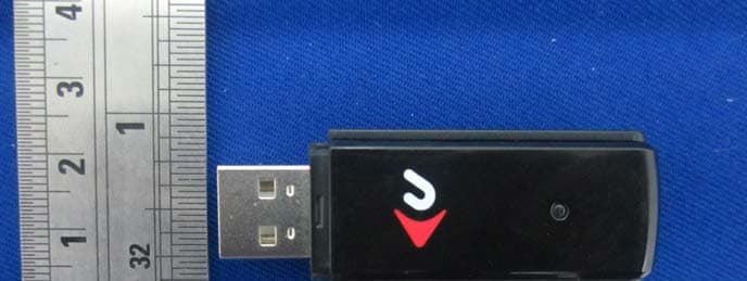
UNH-MXP3802NU2C
Jul 12, 2012802.11n/g/b Wireless USB 2.0 Stick Adapter & Extension Cradle
Equipment Class
DTS - Digital Transmission System
UNH-MXP2802NU2C
Jun 14, 2010802.11n/g/b Wireless USB 2.0 Stick Adapter&Extension Cradle
Equipment Class
DTS - Digital Transmission System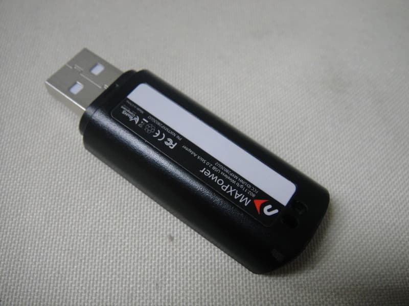
UNH-MXP2802GU2
Jun 13, 2010802.11g/b Wireless USB 2.0 Stick Adapter
Equipment Class
DTS - Digital Transmission System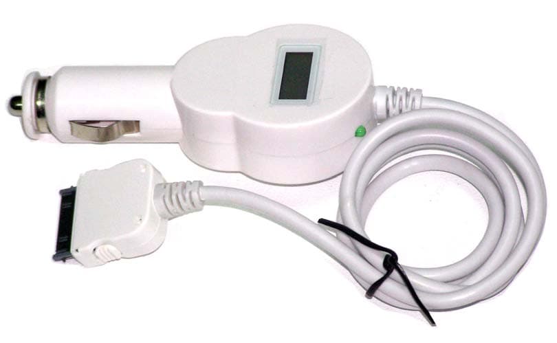
UNHCCH-YY888
Oct 18, 2006TRAFFICJAMZ
Equipment Class
DXX - Part 15 Low Power Communication Device Transmitter