UPMFW330001GSM Dual-band Digital Mobile Phone
Inventec Appliances (Jiangning) Corporation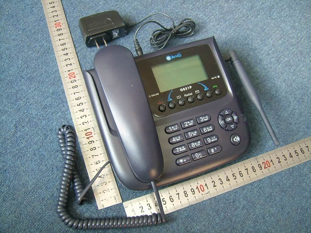
Click to zoom
Application Details
- Equipment Class
- PCB - PCS Licensed Transmitter
- Date of Grant
- Jan 31, 2007
- Application Purpose
- Original Equipment
- Date of Application
- Jan 31, 2007
- Equipment Note
- GSM Dual-band Digital Mobile Phone
- Frequency Range
- 824.20000000 - 848.80000000
- Country
- China
Documents & Files
Document Text
Text extracted from the exhibit documents filed with the FCC. Open a document above to read the original.
Users Manual
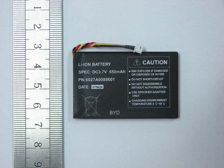
G851P USER GUIDE 1 Your phone at a glance....................................................................................3 For your safety................................................................................................6 Battery and charger.........................................................................................7 Care and maintenance....................................................................................8 Indicators and icons in idle mode....................................................................9 Getting Started..............................................................................................10 2 Your phone at a glance 3 4 1 Handset 2 Online Indicator 3 End key z Press and hold to power the phone on when the phone is off z Press and hold to power the phone off when the phone is in idle z End or reject a call z Return to idle display 4 Left Soft key z Enter the main menu in idle z Execute the function shown at the bottom left of the display 5 Shortcut key for Contacts z Enter the Contacts in idle 6 Redial key z dial out the last number you called 7 Display z 8 Mute Indicator z 9 Shortcut key for SMS z Enter the Message in idle 10 Send key z Make or answer a call z List the dialed calls in idle 11 Right Soft key z Enter the Contacts in idle z Execute the function shown at the bottom right of the display 12 Arrow key z Move the cursor z Press Left/Right arrow key to decrease/increase the earpiece and ring volume 13 OK key z Confirm operations 14 Dual Band ANT z 15 Handfree key z 16 Dial button (Numeric key) z Enter phone numbers, characters or select the function 17 Charger connector z 18 Power key z Shut off the power supply 19 SIM card slot z 20 SIM card z 21 Battery z 22 Battery cover z 23 Jack for handset z 24 Base z 5 For your safety Please read the following guidelines carefully. Failure to comply with them may be dangerous and could affect your warranty. Switch off when refueling Do not use the phone at a petrol station or near fuels or chemicals. Switch off in hospitals Follow all hospital rules and regulations. When near medical equipment, switch off the phone. Anyone with a pacemaker ... Should always keep the phone more than 6 inches from their pacemaker when the phone is turned on. Should use the ear opposite the pacemaker in order to minimize the potential for interference. Should not carry the phone in a breast pocket. Should consult your doctor or the manufacturer of the medical device if you have any questions. Interference All mobile phones may be subject to radio interference, which could affect their performance. Use sensibly Never connect the phone to the charger when the battery has been removed. Accessories and batteries Use only approved accessories and batteries to avoid damage to the phone. The use of any other accessory will invalidate any approval or warranty applying to the phone, and may be dangerous. Qualified service This phone equipment should only be installed or repaired by qualified service personnel. Only qualified service personnel may install or repair this phone equipment. Connecting to other devices Do not connect incompatible products, as this will invalidate your warranty. Emergency calls To make an emergency call, make sure that the phone is switched on and that you have adequate cellular signal strength. Pick up the handset or press the [Hand free] key, enter the emergency number (999, 112 or other official emergency numbers). Once connected, request the appropriate emergency service and clearly relay any details, including your location and contact telephone number. DO NOT end the call until you are told to do so. The antenna(s) used for this transmitter must be installed to provide a separation distance of at least 20 cm from all persons and must not be co-located or operating in conjunction with any other antenna or transmitter. 6 Battery and charger • Only use the battery and charger approved by the manufacturer. • A new battery’s full performance is achieved only after two or three complete charge/discharge cycles. • Be particularly careful when you carry a fully charged battery in your handbag, pocket or other holder containing metal objects (coins, clips, pens, keys, necklaces, etc.). • When the battery is running low and only a few minutes of talk time remain, the screen will prompt a message. When the battery has completely discharged, the phone will switch off automatically. • The battery can be charged and discharged hundreds of times, but it will eventually wear out. When the operating time is noticeably shorter than usual, it is time to buy a new battery. • Before removing the battery, be sure to first switch off your phone. Failure to do so may damage your phone’s memory. • If left unused, a fully charged battery will discharge itself over time. In this condition, if the battery’s voltage is too low, the phone will not display the charging indication until the battery’s voltage is back to normal. After plugging in the charger, please wait for charging indication to be displayed, and then begin normal usage of the handset. • When the charger is not in use, disconnect it from the power source. Do not leave the battery connected to a charger for longer than a week. Overcharging may damage it. • Never use any charger or battery that is damaged or worn out, as this may damage the phone. • Do not put the battery in extremely hot or cold places. This will reduce its capacity and lifetime. Always keep the phone in a cool and dry place. • Batteries must be recycled or disposed of properly. They must not be disposed of with household waste. Do not dispose of batteries in a fire. 7 Care and maintenance Your phone is a product of superior design and manufacture and should be treated with care. The suggestions below will help you enjoy this product for many years. • Keep the phone and all its parts and accessories out of the reach of small children. • Keep it dry. Avoid …
Text truncated - open the document above for the full version.
External Photos
photos
ID Label/Location Info
LCMFront c over of Main B oardCPU Mi cRear c over o f M ain B oardSRAM SpeakerFlash AntennaNumber key Antenna JackFunction key lens
RF Exposure Info
Calculation and sample for Confirmation The maximum measured power output is 1330 mW(1900MHz)/412mW (850MHz), the maximum antenna gain is 2 dBi. The maximum permissible exposure is defined in 47 CFR 1.1310 with 1 mW/cm 2 . The transmitter is using indoor antennas that operate at 20 cm or more from nearby persons. The maximum permitted level is calculated using the general equation: S = P*G/4 πR 2 P = 1330mW(1900MHz)412 mW(850MHz) G = 2 dBi R = 20 cm π = 3.1416 Solving for S, the power density at 20 cm is 0.569 mW/cm 2 .(1900MHz),the power density at 20 cm is 0.163 mW/cm 2 .(850MHz) So The power density limit is 1 mW/cm 2 for GSM1900 and f/1500 mW/cm 2 for GSM850 is kept. Please contact us if you have any additional questions. Best Regards Morlab Jeff Yang Certification Manager
Test Report
Report No. FCC07-8003 Page 2 of 66 Table of Contents 1 Test Report Certification ...............................................................................................................4 2 General Information ......................................................................................................................5 2.1 Description of EUT ...............................................................................................................5 2.2 Objective ...............................................................................................................................6 2.3 Test Standards and Results ....................................................................................................6 2.4 List of Equipments Used .......................................................................................................7 2.5 Test Facility ...........................................................................................................................7 2.6 Environmental conditions .....................................................................................................7 3 Conducted Emission Test ..............................................................................................................8 3.1 Limits of Conducted Emission..............................................................................................8 3.2 Test Procedure .......................................................................................................................8 3.3 Test Setup ..............................................................................................................................9 3.4 EUT Setup and Operating Conditions...................................................................................9 3.5 Test Results ...........................................................................................................................9 4 Radiated Emission Test ............................................................................................................... 11 4.1 Limits of Radiated Emission ............................................................................................... 11 4.2 Test Procedure ..................................................................................................................... 11 4.3 Test Setup ............................................................................................................................12 4.4 EUT Setup and Operating Conditions.................................................................................12 4.5 Test Results .........................................................................................................................12 5 Frequencies .................................................................................................................................14 5.1 Frequency Blocks Available for Cellular Service ...............................................................14 5.2 Frequency Blocks Available for Broadband PCS ...............................................................14 5.3 Test Procedure .....................................................................................................................14 5.4 Test Setup ............................................................................................................................15 5.5 EUT Setup and Operating Conditions.................................................................................15 5.6 Test Results .........................................................................................................................16 6 Conducted RF Output Power Test...............................................................................................18 6.1 RF Power Output Test Requirement ...................................................................................18 6.2 Test Procedure .....................................................................................................................18 6.3 Test Setup ............................................................................................................................18 6.4 EUT Setup and Operating Conditions.................................................................................18 Report No. FCC07-8003 Page 3 of 66 6.5 Test Results .........................................................................................................................19 7 Occupied Bandwidth Test ...........................................................................................................23 7.1 Definition ............................................................................................................................23 7.2 Test Procedure .....................................................................................................................23 7.3 Test Setup ............................................................................................................................23 7.4 EUT Setup and Operating Conditions.................................................................................23 7.5 Test Results .........................................................................................................................24 8 Conducted Spurious Emission Test.............................................................................................27 8.1 Limits of Conducted Spurious Emission.............................................................................27 8.2 Test Procedure .....................................................................................................................27 8.3 Test Setup ............................................................................................................................27 8.4 EUT Setup and Operating Conditions...................................................................…
Text truncated - open the document above for the full version.
Test Setup Photos
Test setup photo
Contact Information
Applicant
William Zhang
Test Firm
ShenZhen Electronic Product Quality Testing CenterXingsun Lin
Technical Specifications
| # | Rule Parts | Frequency Range | Power Output | Emission | Tolerance |
|---|---|---|---|---|---|
| 2 | 22H | 824.2 MHz - 848.8 MHz | 412.00 mW | 300KGXW | 2.5 ppm |
Other Applications from Inventec Appliances (Jiangning) Corporation
UPMFW320001
Dec 14, 2007Dual Band GSM Desktop Phone
Equipment Class
PCB - PCS Licensed Transmitter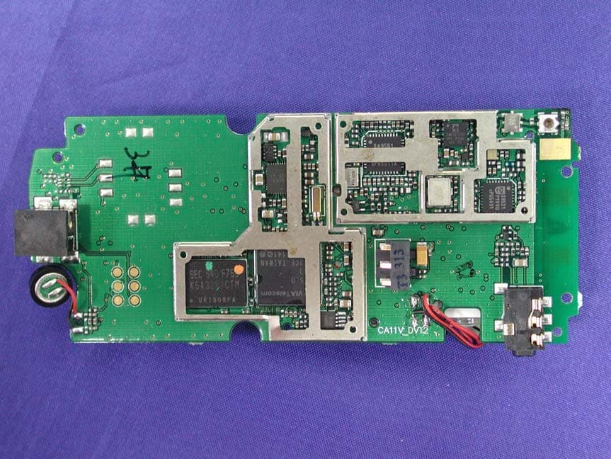
UPMCA11001
Nov 08, 2006CDMA Mobile Phone
Equipment Class
TNE - Licensed Non-Broadcast Transmitter Held to Ear