UQOLC-40TSCENE CONTROLLER
TECHCity Technology Co., Ltd.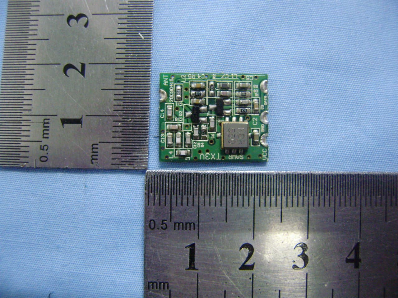
Click to zoom
Application Details
- Equipment Class
- DSC - Part 15 Security/Remote Control Transmitter
- Date of Grant
- Feb 05, 2013
- Application Purpose
- Original Equipment
- Date of Application
- Feb 05, 2013
- Equipment Note
- SCENE CONTROLLER
- Frequency Range
- 433.92000000 - 433.92000000
- Country
- Taiwan
Documents & Files
Document Text
Text extracted from the exhibit documents filed with the FCC. Open a document above to read the original.
Users Manual
1 Product Name : Smart Scene Controller Model No. : LC-X0T Features : z Multi-spot mobile remote control z RF transmit no wiring necessary z 2,3,4,6 touch keys to be programmed easily. z One touch to transmit sigle or multi direction z One extra code to activate a scene controller nearby. (Scene 1~10 for assigned or disable) z N.C. / N.O. dry contact input (Digital Input) to trigger key 1 content z Looks like LC series SW, can be paste on a spot where there has no gang box to take control SW, curtain & appliances. P/N:LC-X0T_20130110 1. Forewords A. Each key of LC-X0T can be programmed as a(n): a. 2-Way SW: to store one single action, such as [1], [ON] (Light No.1, ON). The key become a 2-way SW to every SW set as Light No.1. b. Scene button: to store up to 36 actions including dimming. c. Appliances Activate Button: touch this key to activate a scene, stored in a scene controller nearby (ex. RP-10,12, HC-12) to accomplish a series control of home appliances and lightings. This function can be disabled. B. DI Input: LC-X0T provide one N.C./N.O. input wire to accept trigger signal from various sensors, to carry out a series scene control action pre-stored in key 1. Function Descriptions Specification : z RF Radio Frequency: 433.92 MHz z Power Input : AC - 110V ~ 230V z Use an RC-07 to program a scene & input to a key to store. z If to program a key to become a 2-way SW button, the corresponding SW should be a standard e2-LiVE SW that can be a 2-Way SW control system. NOTE: 2-Way or scene control function is alternative, the Appliances Activation function can be coexistence & Dry Contact input can only activate key 1 scenes. IR Output for scenes’ actions ouput RC-07 2 B. Procedures 0. Practice to feel the press of the setup button with setup stick (A click) 1. Touch & hold a button & press the setup button (press & let go), LED flash 3 times means it’s under setting mode now. You have 7 sec. to input command by RC-07. 2. Pick up an RC-07, which has preset a scene, point its IR Digital Output to the Setup button, within 5cm distance & 5 Sec. at least. 3. When the LED flash twice, it means the process is completed, please put away RC-07. The 2-Way macro input is done. 4. Continue to set the next key or test the key function you’ve just set. C. Control: Touch the key to control in 2-Way mode. 2. 2-Way SW Setup A. Preparation: Pre-set a Macro as a single action as [X], [ON] on a scene button of RC-07. - [X] is the target light no. to be controlled as 2-Way; ex.: the target light no. is “3”. then we need to set a scence [3] [ON] in a scene button on RC-07. (please refer to the user manual of RC-07 to obtain the detail setup procedures.) LC-X0T Setting 3. Scene Control Setup: A. Preset a scene, which contains 36 actions or less; (ex.: “Light no.1 – ON”, “Light no.2 – ON”..., 36 actions are the most). Follow the procedures as “2-Way Setup” to input this macro to any key of LC-X0T, to accomplish the setting. B. Control: Touch a key to start a macro & touch any key to break off the action. ※ Please see appendix for the details to take apart / dress up the front panel. Sense Zones & DI key’s Descriptions 3 Note: 1. This product should be programmed by RC-07. 2. Please contact the distributor near you to obtain correct/updating of product information. 3. Please refer to each manual of HC-12/RP-12/RP-10 for the details of scene (macro) setting. 4. Appliances Activatation Setup A. Procedure: a. Press & hold a key, punch Setup Button with a Setup Stick (punch – feel a click & let go), after LED flash 3 times & off, use setup stick to punch the setup button again, & observe the LED blinking. b. The Sequence of Blinking 1st 2nd 3rd4th5th6th7th8th9th 10th Constant ON for 1 Sec. Macro No. 1 2 3 4 5 6 7 8 9 10 Clear C. As above table, press any key as LED blinking sequence no. indicates the macro you want to assign. & it will confirm the assignment with blinking LED with times as the macro no. you’ve choose. ex.: If the linked macro no. 7, is what you need; when the LED blinks the 7 th , touch any key on LS-330T panel, & the LED will blink 7 times to confirm the macro you’ve selected. At last, the 3 LED will blink 2 times together to leave the setting mode. - If you touch any key as the LED ON for 1 Sec., it means “Clear”, no linked macro code assigned in this setting. - The setting cycle is once at a time, if you do nothing under setting mode. The system will be recovery after LED blinks 10 times & constant ON for 1 Sec. B. Control: a.) Touch the key to send a Linked Macro Activating Code to a controller nearby, after it finished all its preset 2-Way / Macro Control action. b.) Touch any key to break off the action as LC-X0T is transmitting actions. Annex A:Panel Install / uninstall [Uninstall] Put the sucker on the marked spot, press to squeeze out air & make sure the sucker is fixed, then pull out of the panel. [Install] There are 2 latches on the top of the panel, & a crystal in the buttom. there is 2 slot for those 2 latches & a magnet for crystal. PLS make sure the direction correctly. Slide latches into slots first then press the crystal side into the magnet side till the panel sink completely. Pull! FCC WARNING This device complies with Part 15 of the FCC Rules. Operation is subject to the following two conditions: (1) This device may not cause harmful interference, and (2) this device must accept any interference received, including interference that may cause undesired operation. NOTE 1: Any changes or modifications to this unit not expressly approved by the party responsible for compliance could void the user's authority to operate the equipment.
Block Diagram
LC-XOT Circuit Block Diagram AC TO DC RF Transmitter Module LED Indicator & Buzzer IR Rerceiver DATA EEPROM MCU Capacitive Touch Switch
External Photos
TECHCity Technology Co., Ltd. Model:LC-40T REPORT NO.: STR12108167I FCC PART 15.231 EXHIBIT 2 - EUT EXTERNAL PHOTOGRAPHS EUT View 1 EUT View 2 TECHCity Technology Co., Ltd. Model:LC-40T REPORT NO.: STR12108167I FCC PART 15.231 EUT View 3 EUT View 4 TECHCity Technology Co., Ltd. Model:LC-40T REPORT NO.: STR12108167I FCC PART 15.231 EUT View 5 EUT View 6
ID Label/Location Info
TECHCity Technology Co., Ltd. Model:LC-40T REPORT NO.: STR12108167I FCC PART 15.231 EXHIBIT 1- PRODUCT LABELING Proposed FCC ID Label Format FCC ID: UQOLC-40T This device complies with Part 15 of the FCC Rules. Operation is subject to the following two conditions: (1) This device may not cause harmful interference, and (2) this device must accept any interference received, including interference that may cause undesired operation. Specifications : Text is Black in color and justified. Labels are printed in indelible ink on permanent adhesive silk-screened onto the EUT or shall be affixed at a conspicuous location on the EUT. Proposed Label Location on EUT FCC ID Label Location
ID Label/Location Info
TECHCity Technology Co., Ltd. Model:LC-40T REPORT NO.: STR12108167I FCC PART 15.231 EXHIBIT 1- PRODUCT LABELING Proposed FCC ID Label Format FCC ID: UQOLC-40T This device complies with Part 15 of the FCC Rules. Operation is subject to the following two conditions: (1) This device may not cause harmful interference, and (2) this device must accept any interference received, including interference that may cause undesired operation. Specifications : Text is Black in color and justified. Labels are printed in indelible ink on permanent adhesive silk-screened onto the EUT or shall be affixed at a conspicuous location on the EUT. Proposed Label Location on EUT FCC ID Label Location
Internal Photos
TECHCity Technology Co., Ltd. Model:LC-40T REPORT NO.: STR12108167I FCC PART 15.231 EXHIBIT 3 - EUT INTERNAL PHOTOGRAPHS EUT Housing and Board View 1 Solder Board-Component View 1 TECHCity Technology Co., Ltd. Model:LC-40T REPORT NO.: STR12108167I FCC PART 15.231 Solder Board-Component View 2 Solder Board-Component View 3 TECHCity Technology Co., Ltd. Model:LC-40T REPORT NO.: STR12108167I FCC PART 15.231 Solder Board-Component View 4 Solder Board-Component View 5 TECHCity Technology Co., Ltd. Model:LC-40T REPORT NO.: STR12108167I FCC PART 15.231 Solder Board-Component View 6 Solder Board-Component View 7 TECHCity Technology Co., Ltd. Model:LC-40T REPORT NO.: STR12108167I FCC PART 15.231 Solder Board-Component View 8 Antenna View: TX Ant. 433.92MHz
Operational Description
LC-40T Circuit Description 1. AC power pass through AC Module, converting AC power as DC power (12V), then being converted as DC 5Vvia 78L05, to supply M board & T board. The circuit protection part of power board is a 1A fuse for current overload, & surge absorbers deployed at Hot & Load line to prevent sudden surge impact. 2. RF IC:modulate MCU output date,amplify the high-frequency signal and send it to the next stage amplify By Q1 Q2. 3. RF Amplifier:Amplify high-frequency signal of 433.92MHz. 4. MATCHING CIRCUIT:modulate RF IC output impedance,made it matching with the antenna network to output maximal power.
Schematics
NAME: DRN BY: REV: DATE: F 2010/06/11 LC-X0T-M R110 C5 104 1/2W 1 2 F1 FUSE_1 C6104 C7 47u/16V OUT IN GND A1 78L05 黑白 JACKSON VCC V1 470V/10mm DC12V P2.2 23 P2.1 22 P2.0 21 P1.0 20 P1.6 17 VDD 16 P1.3 15 P1.4 14 RST 12 P0.2/INT2 11 P0.1/INT1 10 P0.0/INT0 9 VSS 5 P1.7 4 P2.7 3 P2.6 2 P4.4/AIN4 30 P2.3 24 P4.7/AIN7 27 P4.6/AIN6 28 AVREFL 26 P4.5/AIN5 29 VSS 25 P2.5 1 P5.1/SI 46 P5.0/SCK 47 P3.0 43 P5.3/BZ1/PWM1 44 P5.2/OS 45 P2.4 48 P5.4/BZ0/PWM0 42 P5.6 40 P4.0/AIN0 34 AVREFH 35 VDD 37 DAO 38 P5.7 39 P5.5 41 XOUT 6 XIN 7 VDD 8 P1.1 19 P1.2 18 P4.3/AIN3 31 P4.2/AIN2 32 P4.1/AIN1 33 P1.5 13 AVDD 36 SN8P2708A U1 SN8P2708A(48) VCC 1234 J3 RF_TX ANT A0/WP 1 A2 3 GND 4 A1 2 TEST 7 VCC 8 SCL 6 SDA 5 U224C16/SOP 12 J1CON2 FM-3038LM-5A U3 VCC 1 VOUT 3 GND 2 SW1 0.9mA R13 1.5K R14 1.5K R15 1.5K R10 1.5K R11 1.5K R12 1.5K R8 1.5K R9 1.5K 12 B1BEEP 使使使使使使使使使使所所 MCU 平使平平 High 4MHZXTAL 123 J2CON3 R6100K R5100K NC_INNO_IN VCC C9 104 C8 104 R739K C10104 VCC VCC 1 2 3 4 5 6 7 8 9 10 11 12 13 14 15 16 17 18 J4HEADER 9X2 P20 P21 P22 P23 P24 P25P26P27 P20P21P22P23P24P25P26P27 VCC C11 104 R16 100K R17 100K R18100K Z4 SMDJ12A R23100K R24100K R25100K R26100K R27100K 1234 J5 AC-POWER NeutralLine R30100K R29100K R28100K T_PWR T_PWR 1 2 3 4 5 6 ABCD 6 5 4 3 2 1 D CBA Title Number Revision Size B Date: 19-Sep-2012 Sheet of File: D:\01 -s ong 資資資 \01A2-LC-X0T\02-Layo ut\ 觸觸觸 \20 1101 07-LC 最最最 \MyDesig n\MyDesig n. ddb Drawn By: LC Touch Panel(4KEY) JACKSON REV:J 2010/03/02 LED1 KEY1 KEY2 KEY3 KEY4 LED2 LED3 LED4 ATmega48 ATmega48 KEY1KEY2 KEY4KEY3 1 2 3 4 5 6 7 8 9 10 11 12 13 14 J1HEADER 7X2 C5104 PD3 1 PD4 2 GND 3 VCC 4 GND 5 VCC 6 PB6 7 PB7 8 PD5 9 PD6 10 PD7 11 PB0 12 PB1 13 PB2 14 PB3 15 PB4 16 PB5 17 AVCC 18 AREF 20 ADC6 19 GND 21 ADC7 22 PC0 23 PC1 24 PC2 25 PC3 26 PC4 27 PC5 28 PC6 29 PD0 30 PD1 31 PD2 32 U1ATmega48_MLF-32 VCC VCC PD0PD1PD2 PD3 RST VCC C2104 C3104 5V C4 10u/16VA_TYPE C1 10u/16V Vin 3 GND 2 Vout 1 U3AIC1722A-33CXTTR SOT89 3.3V 1 KEY1CON1 1 KEY2CON1 1 KEY3CON1 1 KEY4CON1 R31 1K R21 1K R11 1K R41 1K C41 223 C31 223 C21 223 C11 223 PD0PD1PD2PD3 VCC 123456 J2CON6 RST MOSIMISOSCK 燒燒 Port C42 223 C32 223 C22 223 C12 223 NAME: DRN BY: REV:DATE: SHEET OF A 11 TX 3V 2008/09/15 C62.7P R3 33 C5102 L1 12nH C815PC7 5P R147K L2 100nH C4470P R4 22K B H D E F L K J SAWR 433.92MHZ C3 220P +3V DATA GND C14100P C1315P L327nH C156P ANT L433nH C12 5P R2 33 R5 470 C11 220P C2104 Q1H10 Q2H10 C9100P
Test Report
TECHCity Technology Co.,Ltd. Model: LC-40T REPORT NO.: STR12108167I PAGE 1 OF 23 FCC PART 15.231 FCC Part 15C Measurement and Test Report For TECHCity Technology Co., Ltd. 4F., No.4, Aly. 1, Siwei Ln., Zhongzheng Rd., Xindian Dist., New Taipei City 231, Taiwan( R.O.C.) FCC ID: UQOLC-40T FCC Rules: FCC Part 15.231 Product Description: Scene Controller Tested Model: LC-40T Report No.: STR12108167I Tested Date: 2012-10-25 to 2012-12-24 Issued Date: 2013-01-09 Tested By: Daniel Liu / Engineer Reviewed By: Lahm Peng / EMC Manager Approved & Authorized By: Jandy so / PSQ Manager Prepared By: SEM.Test Compliance Service Co., Ltd 3/F, Jinbao Commerce Building, Xin'an Fanshen Road, Bao'an District, Shenzhen, P.R.C.(518101) Tel.: +86-755-33663308 Fax.: +86-755-33663309 Website: www.semtest.com.cn Note: This test report is limited to the above client company and the product model only. It may not be duplicated without prior permitted by SEM.Test Compliance Service Co., Ltd TECHCity Technology Co.,Ltd. Model: LC-40T REPORT NO.: STR12108167I PAGE 2 OF 23 FCC PART 15.231 TABLE OF CONTENTS 1. GENERAL INFORMATION ...................................................................................................................................3 1.1 PRODUCT DESCRIPTION FOR EQUIPMENT UNDER TEST (EUT)...............................................................................3 1.2 TEST STANDARDS...................................................................................................................................................4 1.3 TEST METHODOLOGY.............................................................................................................................................4 1.4 TEST FACILITY.......................................................................................................................................................4 1.5 EUT SETUP AND TEST MODE.................................................................................................................................5 2. SUMMARY OF TEST RESULTS ...........................................................................................................................6 3. ANTENNA REQUIREMENT ..................................................................................................................................7 3.1 STANDARD APPLICABLE.........................................................................................................................................7 3.2 TEST RESULT..........................................................................................................................................................7 4. CONDUCTED EMISSIONS ....................................................................................................................................8 4.1 MEASUREMENT UNCERTAINTY..............................................................................................................................8 4.2 TEST EQUIPMENT LIST AND DETAILS.....................................................................................................................8 4.3 TEST PROCEDURE...................................................................................................................................................8 4.4 BASIC TEST SETUP BLOCK DIAGRAM.....................................................................................................................8 4.5 ENVIRONMENTAL CONDITIONS..............................................................................................................................9 4.6 TEST RECEIVER SETUP...........................................................................................................................................9 4.7 SUMMARY OF TEST RESULTS/PLOTS......................................................................................................................9 4.8 CONDUCTED EMISSIONS TEST DATA......................................................................................................................9 5. RADIATED EMISSIONS .......................................................................................................................................12 5.1 MEASUREMENT UNCERTAINTY............................................................................................................................12 5.2 STANDARD APPLICABLE.......................................................................................................................................12 5.3 TEST EQUIPMENT LIST AND DETAILS...................................................................................................................13 5.4 TEST PROCEDURE.................................................................................................................................................13 5.5 CORRECTED AMPLITUDE & MARGIN CALCULATION............................................................................................14 5.6 ENVIRONMENTAL CONDITIONS............................................................................................................................14 5.7 SUMMARY OF TEST RESULTS/PLOTS....................................................................................................................14 6. 20DB BANDWIDTH ...............................................................................................................................................17 6.1 STANDARD APPLICABLE.......................................................................................................................................17 6.2 TEST EQUIPMENT LIST AND DETAILS...................................................................................................................17 6.3 TEST PROCEDURE.................................................................................................................................................17 6.4 ENVIRONMENTAL CONDI…
Text truncated - open the document above for the full version.
Test Setup Photos
TECHCity Technology Co., Ltd. Model:LC-40T REPORT NO.: STR12108167I FCC PART 15.231 EXHIBIT 4 - TEST SETUP PHOTOGRAPHS Conducted Emission Test Setup Radiation Emission Test Setup (Below 30MHz) TECHCity Technology Co., Ltd. Model:LC-40T REPORT NO.: STR12108167I FCC PART 15.231 Radiation Emission Test Setup (30MHz to 1GHz) Radiation Emission Test Setup (Above 1GHz)
Contact Information
Applicant
Sonny Tseng
Test Firm
SEM.Test Compliance Service Co., Ltd.Jandy So
Technical Specifications
| # | Rule Parts | Frequency Range | Power Output |
|---|---|---|---|
| 1 | 15.231 | 433.92 MHz - 433.92 MHz | - |
Other Applications from TECHCity Technology Co., Ltd.

UQORP-20F
Aug 27, 2015Controller
Equipment Class
JBP - Part 15 Class B Computing Device Peripheral
UQOPS-30X
Aug 25, 2015iPower
Equipment Class
DSC - Part 15 Security/Remote Control Transmitter
UQOLC-330C
Feb 05, 2013CURTAIN CONTROLLER
Equipment Class
CYY - Communications Receiver used w/Pt 15 Transmitter
UQOLM-312M
Feb 05, 2013LIGHT SWITCH
Equipment Class
CYY - Communications Receiver used w/Pt 15 TransmitterUQOLM-312P
Feb 05, 2013LIGHT SWITCH
Equipment Class
CYY - Communications Receiver used w/Pt 15 Transmitter