UQOPS-30XiPower
TECHCity Technology Co., Ltd.
Click to zoom
Application Details
- Equipment Class
- DSC - Part 15 Security/Remote Control Transmitter
- Date of Grant
- Aug 25, 2015
- Application Purpose
- Original Equipment
- Date of Application
- Aug 25, 2015
- Equipment Note
- iPower
- Frequency Range
- 433.92000000 - 433.92000000
- Country
- Taiwan
Documents & Files
Document Text
Text extracted from the exhibit documents filed with the FCC. Open a document above to read the original.
Users Manual
e2-Live Home Automation Edit by Shine Lo 1 iPower Smart Power Socket PS-30X Instruction Manual e2-Live Home Automation Edit by Shine Lo 2 iPower Specifications Hardware e2-Live RF Tx/Rx 2 way module Frequency:433.92MHz +/- 150KHz Digital ID coding (0000~9999) Received / Emit distances : open space 60 meters Specifications of loading Power overload protection of recovery fuse x1 3 circuits ON/OFF totally loading 110V 1650W 220V 1800W RS-485 communication,0.1A power fuse Functions 3 circuits sockets Manual tock switch ON/OFF Remote ON/OFF Power detection, checkup the actual power states (with scenario usage of RP-20) With RS-485 two way communication (control or inquiry) Accept e2-Live ALL OFF commands, can be set to enable or disable e2-Live Home Automation Edit by Shine Lo 3 Hardware Appearances 3 circuits total loading are 110V 1650W 220V 1800W While overload happened, iPower will shut down the main power automatically, recover when overload was removed Overload recovery fuse protection, it will shut down automatically to protect iPower itself, and will return to normal situation when overload was removed Used for two way control or inquiry communic ation via RS-485 All circuits can manual ON/OFF switch, with HA power detection of RP-20, please keep the status power on with blue LED extinguish) e2-Live Home Automation Edit by Shine Lo 4 Accessary Power line Note: Special specifications, please with this power line for ipower using in order to make sure correct operations. e2-Live Home Automation Edit by Shine Lo 5 Setting iPower Set up before using : ID & position of remote button Main function is to be controlled wirelessly by all kind of remote controller of e2-Live. General functions : For connected device, which does not need to know the status of power, or judge the function. Tools required: RC -07 scenario remote control, the first zone to third zone RC -09 intelligent remote control, the first zone HT -100 LCD remote control, the first zone to fifth (except zone 1 to 7 ) Itouch lighting / curtain / power supply area (except power zone 1 to 7) RP -20 software, the first zone to fifth (except fifth zone no. 1 to 7) iPower can be set at any position for remote control Actions before setting:: 1. Firstly set up the remote ID, for example: RC -07 / RC 07 / RC-09 must be set up a four-digit ID; itouch or RP -20 software is need to define the four-digit ID through software. 2. Determine iPower's 1 ~ 3 circuits to corresponding position. 3. Determine the connected device accept remote control “All off”. Setting Description: 1.Press and hold the position of wanted circuit, such as the first one. 2.Take a paper clip to poke tact switch in the hole, until the red LED constant light up. 3. Pick up the setting of the Remote Control, press the wanted number, then press “ON” to not accept the "All off" control, press “OFF” to accept the "All off" control. 4. Red LED starts flash (up to 7 times) indicates the setup is successful. 6. After entering the setting mode, there are 15 seconds to setting, if red LED has extinguish that means setting unsuccessfully. e2-Live Home Automation Edit by Shine Lo 6 Using the RC-07 remote control to set the first circuit of iPower Second District, No. 5 position, to accept the "All off" control set 1. Press the button and hold iPower first circuit (1) 2. Setting stick or paper clip poke the tact switch in (2) 3. Press RC-07 (3) 4. Press RC-07 (4) 5. Press RC-07 (5),to accept “All off” control Red LED flashing means successful。 Remote function confirmed: Press RC-07 ,press,press,blue LED extinguish Press RC-07 ,press,press,iPower blue LED light on Press and hold RC-07 ,then press and release both to perform “All off" function,iPower first circuit blue LED light on. Press and hold (1) Setting stick or paper clip poke the tact switch in (2) Red LED light on (2) (3) (4) (5) e2-Live Home Automation Edit by Shine Lo 7 Link connect RP-20, when scenario is been executed, it will detect the power status of your appliances For appliances, used with RP-20 in scenario control, detect the real ON or OFF situation to ensure the accuracy of scenario performance.. Specifies the appliance's remote position setting for number 1 ~ 7 of fifth zone. Require tool:HT-100 LCD remote control, fifth zone position 1 to 7 itouch Power zone position 1 to 7 RP-20 fifth zone position 1 to 7 (The most convenient setting tool) Preparatory actions before setting: 1. Be sure you are well defined the tool ID you wanted 2. Be sure your location is linked to the right appliance. please refer to the corresponding preset value for convenient checking AMP Power → zone 5 No. 1 TV Power →zone 5 No. 2 STB Power →zone 5 No. 3 DVD Power →zone 5 No. 4 CD Power →zone 5 No. 5 CATV Power →zone 5 No. 6 AUX Power →zone 5 No. 7 e2-Live Home Automation Edit by Shine Lo 8 3. Plug in the device corresponding position, adjust to detect the right current consumption when power on and off. Appliances and iPower control location setting is complete and correct detection from the current adjustment, to make sure correct linking function be executed from RP-20.. Specifies light fifth zone 1-7 for power detection position. For example: 1. Connect to PC with RP-20 via USB, open RP-20 software, checking COM connection. 2. RP-20 software provides two places available to transfer ID code (1) Home page: power control coding. The mode is not accept “All off”. Illustrated as follows (2) Control Validation:in ” light & curtain” select accept “All off” or not accept “All off”. 3. In setting mode (1) Press and hold (2) poke the tact switch in setting hole, red LED light on 4. Using RP-20 home page to transfer code, as shown below (一) Using Control Validation/ Light & Curtain to transfer code,as shown below(二),step3~5 5. iPower received , red LED quick flashing means setting successfully. Press and hold (1) Setting stick or paper clip poke the tact switch in (2) Red LED light on (2) e2-Live Home Automatio…
Text truncated - open the document above for the full version.
External Photos
TECHCITY TECHNOLOGY CO., LTD. Model: PS-30X REPORT NO.: STR15078227I FCC PART 15.231 EXHIBIT 2 - EUT EXTERNAL PHOTOGRAPHS EUT View 1 EUT View 2 TECHCITY TECHNOLOGY CO., LTD. Model: PS-30X REPORT NO.: STR15078227I FCC PART 15.231 EUT View 3 EUT View 4
ID Label/Location Info
TECHCITY TECHNOLOGY CO., LTD. Model: PS-30X REPORT NO.: STR15078227I FCC PART 15.231 EXHIBIT 1 - PRODUCT LABELING Proposed FCC ID Label Format FCC ID: UQOPS-30X This device complies with Part 15 of the FCC Rules. Operation is subject to the following two conditions: (1) This device may not cause harmful interference, and (2) this device must accept any interference received, including interference that may cause undesired operation. Specifications: Text is Black in color and justified. Labels are printed in indelible ink on permanent adhesive silk-screened onto the EUT or shall be affixed at a conspicuous location on the EUT. Proposed Label Location on EUT FCC ID Label Location
Internal Photos
TECHCITY TECHNOLOGY CO., LTD. Model: PS-30X REPORT NO.: STR15078227I FCC PART 15.231 EXHIBIT 3 - EUT INTERNAL PHOTOGRAPHS EUT Housing and Board View 1 Solder Board-Component View 1 TECHCITY TECHNOLOGY CO., LTD. Model: PS-30X REPORT NO.: STR15078227I FCC PART 15.231 Solder Board-Component View 2 Solder Board-Component View 3 RF Antenna TECHCITY TECHNOLOGY CO., LTD. Model: PS-30X REPORT NO.: STR15078227I FCC PART 15.231 Solder Board-Component View 4 Solder Board-Component View 5 TECHCITY TECHNOLOGY CO., LTD. Model: PS-30X REPORT NO.: STR15078227I FCC PART 15.231 Solder Board-Component View 6 Solder Board-Component View 7
Test Report
TECHCITY TECHNOLOGY CO., LTD. Model: PS-30X REPORT NO.: STR15078227I PAGE 1 OF 23 FCC PART 15.231 FCC Part 15C Measurement and Test Report For TECHCITY TECHNOLOGY CO., LTD. 4F, No. 4, Alley 1, Szu Wei Lane, Chung Cheng Rd, Hsin Tien Taipei Hsien, Taiwan, R.O.C. FCC ID: UQOPS-30X FCC Rule(s): FCC Part 15.231 Product Description: iPower Tested Model: PS-30X Report No.: STR15078227I Tested Date: 2015-07-18 to 2015-08-04 Issued Date: 2015-08-04 Tested By: Jong Wang / Engineer Reviewed By: Lahm Peng / EMC Manager Approved & Authorized By: Jandy so / PSQ Manager Prepared By: Shenzhen SEM.Test Technology Co., Ltd. 1/F, Building A, Hongwei Industrial Park, Liuxian 2nd Road, Bao'an District, Shenzhen, P.R.C.(518101) Tel.: +86-755-33663308 Fax.: +86-755-33663309 Website: www.semtest.com.cn Note: This test report is limited to the above client company and the product model only. It may not be duplicated without prior permitted by Shenzhen SEM.Test Technology Co., Ltd. TECHCITY TECHNOLOGY CO., LTD. Model: PS-30X REPORT NO.: STR15078227I PAGE 2 OF 23 FCC PART 15.231 TABLE OF CONTENTS 1. GENERAL INFORMATION ...................................................................................................................................3 1.1 P RODUCT D ESCRIPTION FOR E QUIPMENT U NDER T EST (EUT) ...............................................................................3 1.2 T EST S TANDARDS ...................................................................................................................................................4 1.3 T EST M ETHODOLOGY .............................................................................................................................................4 1.4 T EST F ACILITY .......................................................................................................................................................4 1.5 EUT S ETUP AND T EST M ODE .................................................................................................................................5 1.6 T EST E QUIPMENT L IST AND D ETAILS .....................................................................................................................5 2. SUMMARY OF TEST RESULTS ...........................................................................................................................6 3. ANTENNA REQUIREMENT ..................................................................................................................................7 3.1 S TANDARD A PPLICABLE .........................................................................................................................................7 3.2 T EST R ESULT ..........................................................................................................................................................7 4. CONDUCTED EMISSIONS ....................................................................................................................................8 4.1 M EASUREMENT U NCERTAINTY ..............................................................................................................................8 4.2 T EST P ROCEDURE ...................................................................................................................................................8 4.3 B ASIC T EST S ETUP B LOCK D IAGRAM .....................................................................................................................8 4.4 E NVIRONMENTAL C ONDITIONS ..............................................................................................................................9 4.5 T EST R ECEIVER S ETUP ...........................................................................................................................................9 4.6 S UMMARY OF T EST R ESULTS /P LOTS ......................................................................................................................9 4.7 C ONDUCTED E MISSIONS T EST D ATA ......................................................................................................................9 5. RADIATED EMISSIONS ....................................................................................................................................... 12 5.1 M EASUREMENT U NCERTAINTY ............................................................................................................................ 12 5.2 S TANDARD A PPLICABLE ....................................................................................................................................... 12 5.3 T EST P ROCEDURE ................................................................................................................................................. 13 5.4 C ORRECTED A MPLITUDE & M ARGIN C ALCULATION ............................................................................................ 14 5.5 E NVIRONMENTAL C ONDITIONS ............................................................................................................................ 14 5.6 S UMMARY OF T EST R ESULTS /P LOTS .................................................................................................................... 14 6. 20DB BANDWIDTH ............................................................................................................................................... 17 6.1 S TANDARD A PPLICABLE ....................................................................................................................................... 17 6.1 T EST P ROCEDURE ................................................................................................................................................. 17 6.2 E NVIRONMENTAL C ONDITIONS ............................................................................................................................ 17 6.3 S UMMARY OF T EST R ESULTS /P LOTS ....................................…
Text truncated - open the document above for the full version.
Test Setup Photos
TECHCITY TECHNOLOGY CO., LTD. Model: PS-30X REPORT NO.: STR15078227I FCC PART 15.231 EXHIBIT 4 - TEST SETUP PHOTOGRAPHS Conducted Emission Test Setup Radiation Emission Test Setup (30MHz to 1GHz) TECHCITY TECHNOLOGY CO., LTD. Model: PS-30X REPORT NO.: STR15078227I FCC PART 15.231 Radiation Emission Test Setup (Above 1GHz)
Contact Information
Applicant
Sonny Tseng
Test Firm
Shenzhen SEM.Test Technology Co., Ltd.Jandy So
Technical Specifications
| # | Rule Parts | Frequency Range | Power Output |
|---|---|---|---|
| 1 | 15.231 | 433.92 MHz - 433.92 MHz | - |
Other Applications from TECHCity Technology Co., Ltd.

UQORP-20F
Aug 27, 2015Controller
Equipment Class
JBP - Part 15 Class B Computing Device Peripheral
UQOLC-330C
Feb 05, 2013CURTAIN CONTROLLER
Equipment Class
CYY - Communications Receiver used w/Pt 15 Transmitter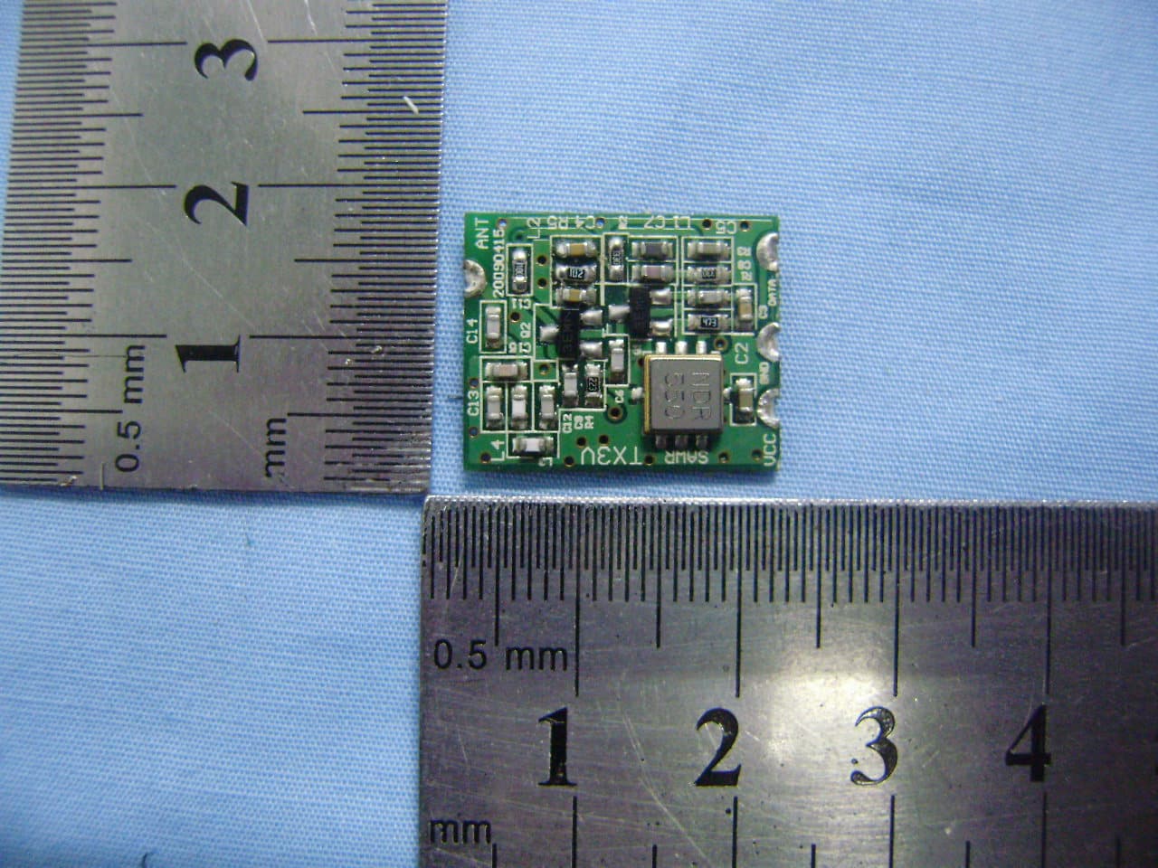
UQOLC-40T
Feb 05, 2013SCENE CONTROLLER
Equipment Class
DSC - Part 15 Security/Remote Control Transmitter
UQOLM-312M
Feb 05, 2013LIGHT SWITCH
Equipment Class
CYY - Communications Receiver used w/Pt 15 TransmitterUQOLM-312P
Feb 05, 2013LIGHT SWITCH
Equipment Class
CYY - Communications Receiver used w/Pt 15 Transmitter