UQUGT900001GPS Tracking Device
Columbus Nova Technology Group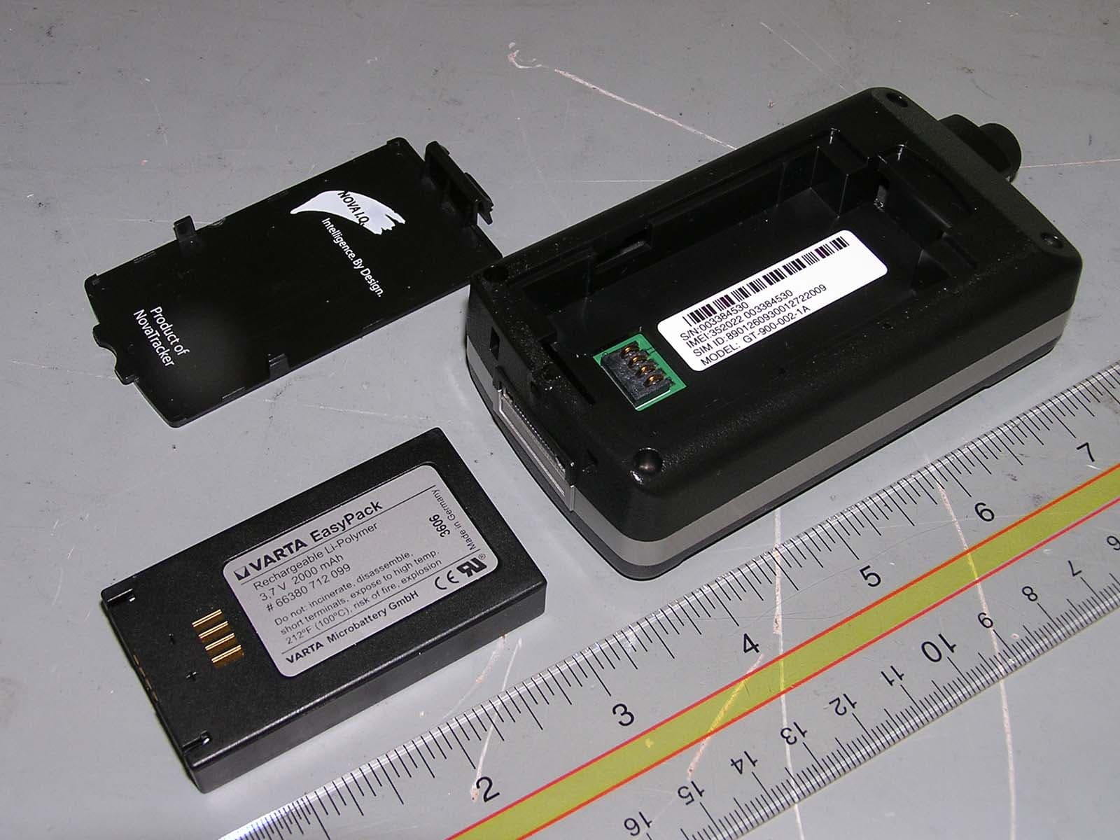
Click to zoom
Application Details
- Equipment Class
- PCE - PCS Licensed Transmitter held to ear
- Date of Grant
- Nov 06, 2007
- Application Purpose
- Original Equipment
- Date of Application
- Nov 06, 2007
- Equipment Note
- GPS Tracking Device
- Frequency Range
- 1850.20000000 - 1909.80000000
- Country
- United States
Documents & Files
Document Text
Text extracted from the exhibit documents filed with the FCC. Open a document above to read the original.
Users Manual
NovaTracker 11 Commerce Dr Cranford, NJ 07016 908 272 0114 Doc No: GT-400-003-02DoD GUARDTRAX Personnel Tracking Solutions for the Security Industry (DoD) USER & OPERATING MANUAL GUARDTRAX USER & OPERATING MANUAL NovaTracker 11 Commerce Dr Cranford, NJ 07016 908 272 0114 Doc No: GT-400-003-02DoD ii Table of Contents 1 DESCRIPTION 1 1.1 Features, Advantages and Benefits 1 2 OPERATIONAL OVERVIEW 3 2.1 Requirements for Operation 3 3 DETAILED OPERATION 4 3.1 Basic operation 4 3.2 Key Sequences 5 3.2.1 User-key Sequence 5 3.2.2 Reserved-key Sequence 6 3.3 In-coming and Out-going CALL Processing 7 3.3.1 In-coming CALL Sequence 7 3.3.2 Out-going CALL Sequence 8 3.4 Geo-fence 8 3.5 Charge message 8 4 GUARDTRAX TECHNICAL SPECIFICATIONS 9 4.1 GSM/GPRS Support 9 4.2 GSM/GPRS Modem Specifications 9 4.3 GPS Engine Specifications 9 GUARDTRAX USER & OPERATING MANUAL NovaTracker 11 Commerce Dr Cranford, NJ 07016 908 272 0114 Doc No: GT-400-003-02DoD iii 4.4 Accuracy 10 4.5 Environmental & Electrical Specifications 10 4.6 Power Consumption 10 4.7 Physical Specifications 10 4.8 Accessories 11 4.9 Interfaces 11 5 UNDERSTANDING THE LEDs 12 6 KEY SEQUENCES 13 6.1 Panic and Hot-key Events 13 6.2 Out-going-Call-Key Events 13 6.3 5-Key Sequence Events 13 GUARDTRAX USER & OPERATING MANUAL NovaTracker 11 Commerce Dr Cranford, NJ 07016 908 272 0114 Doc No: GT-400-003-02DoD iv RADIO FREQUENCY RADIATION EXPOSURE INFORMATION: For body worn operation, this phone has been tested and meets the FCC RF exposure guidelines when used with an accessory that contains no metal and that positions the handset a minimum of 0cm from the body. Use of other accessories may not ensure compliance with FCC RF exposure guidelines. GUARDTRAX USER & OPERATING MANUAL NovaTracker 11 Commerce Dr Cranford, NJ 07016 908 272 0114 Doc No: GT-400-003-02DoD 1 1 DESCRIPTION The NovaTracker GuardTrax security-tracking unit provides a convenient way for a security firm to maintain contact with its most important asset, their personnel. Whether in an outdoor environment or inside structures with an adequate view of the sky the GPS (global positioning system) tracking and GSM (global system for mobile communications) network compatibility of the GuardTrax unit make it a convenient way to acquire near instantaneous feedback on guard location and status. The unit is battery supported, fully portable and self contained in a durable plastic housing. 1.1 Features, Advantages and Benefits 9 Report location and guard station status over the GPRS (general packet radio service) data network using the GuardTrax’s multifunction keys. 9 Initiate an outgoing voice call to a pre-programmed terminal station via the GuardTrax red panic key. 9 Send voice through the GSM cellular network and data transactions through the GPRS cellular data networks. 9 IP based messaging protocol allows the unit to direct messages to any internet- enabled portal for graphical as well a textual security monitoring. 9 GPS and GSM status indicator LEDs allow the user to determine network connectivity. 9 Autonomous location and status message are initiated via the GuardTrax integrated motion detector. No personnel interaction is required. 9 A replaceable, rechargeable Lithium-Ion battery pack provides hours of uninterrupted portable operation. 9 An integrated speaker and microphone or an optional hands-free headset provides voice communication functionality. The benefit of the GuardTrax unit to you and your security force is in its ability to determine and communicate security related events with little to no personnel interaction. GUARDTRAX USER & OPERATING MANUAL NovaTracker 11 Commerce Dr Cranford, NJ 07016 908 272 0114 Doc No: GT-400-003-02DoD 2 The GuardTrax unit can determine if: 9 guard is in motion 9 guard is on the assigned property 9 guard has visited assigned station(s) accommodated through 5-key sequence codes GUARDTRAX USER & OPERATING MANUAL NovaTracker 11 Commerce Dr Cranford, NJ 07016 908 272 0114 Doc No: GT-400-003-02DoD 3 2 OPERATIONAL OVERVIEW While in motion the unit will transmit time and GPS location messages using IP protocol in response to user-selectable key sequences, time, or motion events over the GSM cellular network. If the device is out of GSM range then, data messages are stored and transmitted in reverse chronological Last-in-First-Out (LIFO) order when the device is back in range. The unit has the ability to store approximately 3000 data messages. For the GuardTrax unit the default key sequence is 5-keys in length. The meaning of each sequence is user defined at the server application level. A regional geo-fence feature is also included. A user can program up to 25 non- overlapping circular regions. The geo-fence region is defined as a center point latitude and longitude, and a radius. A red panic key is included for emergencies. This key sends a time and location message via a GPRS cellular data network, and initiates a GSM cellular network voice call to a pre-programmed phone number. 2.1 Requirements for Operation 9 For optimum GPS reception, the unit must have an unobstructed 120-degree circular view to sky. 9 To receive and transmit messages the unit must be deployed in an area with adequate GSM and GPRS cellular network coverage. 9 A GSM network compatible SIM (subscriber identity module) card with caller ID activated is installed in the unit. The SIM card is factory installed. Only an authorized dealer can locate and manage SIM card insertion and activation. 9 GuardTrax should be operated with a fully charged Lithium-Ion battery, and should be charged in its cradle 3-4 hours/night. GUARDTRAX USER & OPERATING MANUAL NovaTracker 11 Commerce Dr Cranford, NJ 07016 908 272 0114 Doc No: GT-400-003-02DoD 4 3 DETAILED OPERATION The GuardTrax unit is compatible with the GSM/GPRS voice and data cellular network and is capable of receiving GPS time and location information. The unit operates on a time, motion and key entry event driven basis. Compressed data and …
Text truncated - open the document above for the full version.
Cover Letter(s)
Federal Communication Commission Equipment Authorization Division, Application Processing Branch 7435 Oakland Mills Road Columbia, MD 21048 Date:October19, 2007 To Whom It May Concern: Pursuant to Paragraphs §0.457 and 0.459 of theCommission’s Rules (47 C.F.R.) and Section §552(b)(4) of the Freedom of Information Act,Columbus Nova Technology Group, LLC DBA NovaTrackerrequests confidentiality for the following products: FCC ID Number ProductTitle/Model UQUGT900001GuardTrax For the productstated above, we request that the following information be held confidential: 1)Electrical Schematics of the Circuitry 2)Block Diagram 3)Parts List 4)Tune-up Procedure 5)Operational Description No other items submitted as part of the equipment authorization filing process are deemed confidential. The above exhibitscontainColumbus Nova Technology Group, LLC DBA NovaTrackertradesecrets and proprietary information that could be of benefit to our competitors regarding the design of our mobile handset. This material is not customarily available to the general public and we request that it be withheld from public inspection. If you have any questions, please feel free to contact me at the address shown below. Sincerely, Tracy Kan Tracy Kan 11Commerce Drive,Lobby Floor Cranford, NJ 07016 Tel: 908-272-0114
ID Label/Location Info
GT-700- 030 LABEL, HAND HELD REV 2 John Koch 10/10/2007 .62 1.6 “ NOTES:1. Obtain blank label from American Printing Company, Part number 2. Dimensions in inches .XX + - .015.XXX + - .010 9-DIGIT BARCODE9-DIGIT NUMBERIMEI NUMBERSIM CARD NUMBERMODEL: GT-900 001-1AFCC ID: UQUGT900001
ID Label/Location Info
GT-700- 030 LABEL, HAND HELD REV 2 John Koch 10/10/2007 .62 1.6 “ NOTES:1. Obtain blank label from American Printing Company, Part number 2. Dimensions in inches .XX + - .015.XXX + - .010 9-DIGIT BARCODE9-DIGIT NUMBERIMEI NUMBERSIM CARD NUMBERMODEL: GT-900 001-1AFCC ID: UQUGT900001
Internal Photos
411 Dixon Landing Rd. Milpitas, CA 95035 Phone:(408)586-6200 Fax:(408)586-6299 Page 10 of 25 Internal Photos: NovaTracker GuardTrax Component Layout GPS Antenna GSM Modem SIM Card Holder Battery & Inerface PCB Main PCB Main PCB with GSM modem and battery PCB removed
RF Exposure Info
SAR Test Report No.: SAR_NOVA1_007_07002_GuardTrax_FCC Date of Report: 10/15/2007 Appendix A Plots Page 1 of 22 System / software: SARA2 / 2.40 VPM Input Power Drift: Date / Time: 9/25/2007 10:11:00 AM DUT Battery Model/No: Filename: Left_Tilt_190_3d.txt Probe Serial Number: M0024 Ambient Temperature: 22.8°C Liquid Simulant: 850 Device Under Test: GuardTrax with MC56 Relative Permittivity: 41.39 Relative Humidity: 30% Conductivity: 0.917 Phantom S/No: Head04_37.csv Liquid Temperature: 22.0°C Phantom Rotation: 180° Max SAR Y-axis Location: 50.00 mm DUT Position: Right Touch Max SAR Z-axis Location: -180.00 mm Antenna Configuration: Integral Max E Field: 7.10 V/m Test Frequency: 836.6MHz SAR 1g: 0.041 W/kg Air Factors: 2685 / 2277 / 2238 SAR 10g: Conversion Factors: .360 / .360 / .360 SAR Start: 0.021 W/kg Type of Modulation: SAR End: 0.022 W/kg Modn. Duty Cycle: SAR Drift during Scan: 4.76 % Diode Compression Factors (V*200): 20 / 20 / 20 Probe battery last changed: 10/11/07 Input Power Level: PCL 5 Extrapolation: poly4 SAR Test Report No.: SAR_NOVA1_007_07002_GuardTrax_FCC Date of Report: 10/15/2007 Appendix A Plots Page 2 of 22 System / software: SARA2 / 2.40 VPM Input Power Drift: Date / Time: 9/25/2007 11:14:12 AM DUT Battery Model/No: Filename: Right_Touch_190_3dc.t xt Probe Serial Number: M0024 Ambient Temperature: 22.8°C Liquid Simulant: 850 Device Under Test: GuardTrax with MC56 Relative Permittivity: 41.39 Relative Humidity: 30% Conductivity: 0.917 Phantom S/No: Head04_37.csv Liquid Temperature: 22.0°C Phantom Rotation: 180° Max SAR Y-axis Location: 12.00 mm DUT Position: Right Tilt Max SAR Z-axis Location: -118.25 mm Antenna Configuration: Integral Max E Field: 11.72 V/m Test Frequency: 836.6MHz SAR 1g: 0.083 W/kg Air Factors: 2685 / 2277 / 2238 SAR 10g: Conversion Factors: .360 / .360 / .360 SAR Start: 0.054 W/kg Type of Modulation: SAR End: 0.052 W/kg Modn. Duty Cycle: SAR Drift during Scan: -3.92 % Diode Compression Factors (V*200): 20 / 20 / 20 Probe battery last changed: 10/11/07 Input Power Level: PCL 5 Extrapolation: poly4 SAR Test Report No.: SAR_NOVA1_007_07002_GuardTrax_FCC Date of Report: 10/15/2007 Appendix A Plots Page 3 of 22 System / software: SARA2 / 2.40 VPM Input Power Drift: Date / Time: 9/25/2007 8:50:39 AM DUT Battery Model/No: Filename: temp.txt Probe Serial Number: M0024 Ambient Temperature: 22.8°C Liquid Simulant: 850 Device Under Test: GuardTrax with MC56 Relative Permittivity: 41.39 Relative Humidity: 30% Conductivity: 0.917 Phantom S/No: Head04_37.csv Liquid Temperature: 22.0°C Phantom Rotation: 0° Max SAR Y-axis Location: -37.00 mm DUT Position: Left Touch Max SAR Z-axis Location: -131.00 mm Antenna Configuration: Integral Max E Field: 9.88 V/m Test Frequency: 836.6MHz SAR 1g: 0.071 W/kg Air Factors: 2685 / 2277 / 2238 SAR 10g: Conversion Factors: .360 / .360 / .360 SAR Start: 0.045 W/kg Type of Modulation: SAR End: 0.046 W/kg Modn. Duty Cycle: SAR Drift during Scan: 2.23 % Diode Compression Factors (V*200): 20 / 20 / 20 Probe battery last changed: 10/11/07 Input Power Level: PCL 5 Extrapolation: poly4 SAR Test Report No.: SAR_NOVA1_007_07002_GuardTrax_FCC Date of Report: 10/15/2007 Appendix A Plots Page 4 of 22 System / software: SARA2 / 2.40 VPM Input Power Drift: Date / Time: 9/25/2007 9:22:01 AM DUT Battery Model/No: Filename: Left_Touch_190_3d.txt Probe Serial Number: M0024 Ambient Temperature: 22.8°C Liquid Simulant: 850 Device Under Test: GuardTrax with MC56 Relative Permittivity: 41.39 Relative Humidity: 30% Conductivity: 0.917 Phantom S/No: Head04_37.csv Liquid Temperature: 22.0°C Phantom Rotation: 0° Max SAR Y-axis Location: -11.00 mm DUT Position: Left Tilt Max SAR Z-axis Location: -95.00 mm Antenna Configuration: Integral Max E Field: 20.66 V/m Test Frequency: 836.6MHz SAR 1g: 0.231 W/kg Air Factors: 2685 / 2277 / 2238 SAR 10g: Conversion Factors: .360 / .360 / .360 SAR Start: 0.069 W/kg Type of Modulation: SAR End: 0.070 W/kg Modn. Duty Cycle: SAR Drift during Scan: 2.03 % Diode Compression Factors (V*200): 20 / 20 / 20 Probe battery last changed: 10/11/07 Input Power Level: PCL 5 Extrapolation: poly4 SAR Test Report No.: SAR_NOVA1_007_07002_GuardTrax_FCC Date of Report: 10/15/2007 Appendix A Plots Page 5 of 22 System / software: SARA2 / 2.40 VPM Input Power Drift: Date / Time: 9/25/2007 12:02:52 PM DUT Battery Model/No: Filename: Left_Tilt_128_3d.txt Probe Serial Number: M0024 Ambient Temperature: 22.8°C Liquid Simulant: 850 Device Under Test: GuardTrax with MC56 Relative Permittivity: 41.83 Relative Humidity: 30% Conductivity: 0.911 Phantom S/No: Head04_37.csv Liquid Temperature: 22.0°C Phantom Rotation: 0° Max SAR Y-axis Location: 0.00 mm DUT Position: Left Tilt Max SAR Z-axis Location: -104.00 mm Antenna Configuration: Integral Max E Field: 10.97 V/m Test Frequency: 824.2MHz SAR 1g: 0.086 W/kg Air Factors: 2685 / 2277 / 2238 SAR 10g: Conversion Factors: .360 / .360 / .360 SAR Start: 0.052 W/kg Type of Modulation: SAR End: 0.050 W/kg Modn. Duty Cycle: SAR Drift during Scan: -3.85 % Diode Compression Factors (V*200): 20 / 20 / 20 Probe battery last changed: 10/11/07 Input Power Level: PCL 5 Extrapolation: poly4 SAR Test Report No.: SAR_NOVA1_007_07002_GuardTrax_FCC Date of Report: 10/15/2007 Appendix A Plots Page 6 of 22 System / software: SARA2 / 2.40 VPM Input Power Drift: Date / Time: 9/25/2007 12:28:35 PM DUT Battery Model/No: Filename: Left_Tilt_251_3d.txt Probe Serial Number: M0024 Ambient Temperature: 22.8°C Liquid Simulant: 850 Device Under Test: GuardTrax with MC56 Relative Permittivity: 41.31 Relative Humidity: 30% Conductivity: 0.923 Phantom S/No: Head04_37.csv Liquid Temperature: 22.0°C Phantom Rotation: 0° Max SAR Y-axis Location: -15.33 mm DUT Position: Left Tilt Max SAR Z-axis Location: -99.00 mm Antenna Configuration: Integral Max E Field: 11.84 V/m Test Frequency: 848.8MHz SAR 1g: 0.113 W/kg Air Factors: 2685 / 2277 / 2238 SAR 10g: Conversion Factors: .360 / .360 / .360 SAR Start: 0.051 W/kg Type of Modulation: SAR End:…
Text truncated - open the document above for the full version.
RF Exposure Info
SAR Test Report No.: SAR_NOVA1_007_07002_GuardTrax_FCC Date of Report:10/15/2007 Appendix B Page 1 of 7 Appendix B: Photos Photo 1. Right Touch Position SAR Test Report No.: SAR_NOVA1_007_07002_GuardTrax_FCC Date of Report:10/15/2007 Appendix B Page 2 of 7 Photo 2. Right Tilt Position SAR Test Report No.: SAR_NOVA1_007_07002_GuardTrax_FCC Date of Report:10/15/2007 Appendix B Page 3 of 7 Photo 3. Left Touch Position SAR Test Report No.: SAR_NOVA1_007_07002_GuardTrax_FCC Date of Report:10/15/2007 Appendix B Page 4 of 7 Photo 4. Left Tilt Position SAR Test Report No.: SAR_NOVA1_007_07002_GuardTrax_FCC Date of Report:10/15/2007 Appendix B Page 5 of 7 Photo 5. Back Position SAR Test Report No.: SAR_NOVA1_007_07002_GuardTrax_FCC Date of Report:10/15/2007 Appendix B Page 6 of 7 Photo 6. Front Position SAR Test Report No.: SAR_NOVA1_007_07002_GuardTrax_FCC Date of Report:10/15/2007 Appendix B Page 7 of 7 Photo 4: Photo to demonstrate 15 cm Z-axis flat phantom
RF Exposure Info
SAR Test Report No: SAR_NOVA1_007_07002_GuardTrax_FCC Date of Report: 10/15/2007 Appendix C Page 1 of 11 Tissue Parameters 850MHz Head liquid: Recipe: The following recipe is provided in percentage by weight. 49.46% distilled water 49.46% DGBE 1.0% salt 0.1% bactericide SAR measurements were made within 24 hours of the measurement of liquid parameters. Freq. Rel. Condy Date (MHz) Perm. (S/m) 09/25/2007 824.2 41.83 0.911 09/25/2007 835 41.73 0.901 09/25/2007 836.6 41.39 0.917 09/25/2007 848.8 41.31 0.923 850MHz Body Liquid: Recipe: The following recipe is provided in percentage by weight. 49.8% distilled water 40.6% DGBE 8.9% salt 0.6% HEC 0.1% bactericide SAR measurements were made within 24 hours of the measurement of liquid parameters. Freq. Rel. Condy Date (MHz) Perm. (S/m) 09/25/2007 824.2 56.07 0.973 09/25/2007 836.6 55.75 0.987 09/25/2007 848.8 55.45 0.983 SAR Test Report No: SAR_NOVA1_007_07002_GuardTrax_FCC Date of Report: 10/15/2007 Appendix C Page 2 of 11 1900MHz Head liquid: Recipe: The following recipe is provided in percentage by weight. 54.9% distilled water 44.92% DGBE 0.18% salt 0.1% bactericide SAR measurements were made within 24 hours of the measurement of liquid parameters. Freq. Rel. Condy Date (MHz) Perm. (S/m) 10/12/2007 1850.2 40.42 1.339 10/12/2007 1880 40.31 1.357 10/12/2007 1900 39.78 1.421 10/12/2007 1909.8 39.83 1.368 1900MHz Body Liquid: Recipe: The following recipe is provided in percentage by weight. 69.17% distilled water 30.29% DGBE 0.44% salt 0.1% bactericide SAR measurements were made within 24 hours of the measurement of liquid parameters. Freq. Rel. Condy Date (MHz) Perm. (S/m) 10/12/2007 1850.2 53.26 1.505 10/12/2007 1880 53.01 1.536 10/12/2007 1909.8 53.11 1.559 SAR Test Report No: SAR_NOVA1_007_07002_GuardTrax_FCC Date of Report: 10/15/2007 Appendix C Page 3 of 11 Test Equipment Test Equipment Model Serial Instrument description Supplier / Manufacturer Model Serial No. Calibration (date) Calibration Due (date) Bench top Robot Mitsubishi supplied by IndexSAR RV-E2 EA1030108 N/A N/A SAM Phantom Upright shell phantom made by Antennessa digitized and mounted by IndexSAR SAM 03FT26 04/03 N/A Flat Phantom IndexSAR HeadBox_1 N/A N/A N/A Software IndexSAR SARA2 v0.420 N/A N/A N/A 850 MHz Head Tissue Simulant Cetecom Inc. 850 Head N/A 09/25/2007 N/A 850 MHz Body Tissue Simulant Cetecom Inc. 850 Body N/A 09/25/2007 N/A 1900 MHz Head Tissue Simulant Cetecom Inc. 1900 Head N/A 10/12/2007 N/A 1900 MHz Body Tissue Simulant Cetecom Inc. 1900 Body N/A 10/12/2007 N/A 835 MHz Dipole IndexSAR – IEEE 1528 design IXDA-083 0016 08/14/2007 08/14/2008 1900 MHz Dipole IndexSAR – IEEE 1528 design IXDA-188 0016 08/15/2007 08/15/2008 Directional coupler Werlatone C6529 11249 N/A N/A RF Amplifier Vectawave VTL5400 N/A N/A N/A SAR Probe IndexSAR IXP-050 S/N 0016 10/20/2006 10/20/2007 SAR Probe IndexSAR IXP-030 S/N M0024 12/13/2006 12/13/2007 Dielectric Measurement Kit IndexSAR Di-Line N/A N/A N/A SAR Test Report No: SAR_NOVA1_007_07002_GuardTrax_FCC Date of Report: 10/15/2007 Appendix C Page 4 of 11 Equipment Calibration/Performance Documents: Validation Dipoles Performance Measurements: Pages 5 to 11 Please Note: (The following pages of Appendix C show calibration documents. These calibration documents are inserted into this appendix. The header information with page numbering scheme is a part of this report and is included on all pages of the report and appendixes. This header is used to track all of the contents of this report.) SAR Test Report No: SAR_NOVA1_007_07002_GuardTrax_FCC Date of Report: 10/15/2007 Appendix C Page 5 of 11 Report No. SN0016_090-180-190-245 July 1 st 2002 Revised 08/16/2007 INDEXSAR Validation Dipoles Type IXD-090, IXD-180, IXD-190 & IXD-245 Performance measurements S/N: 090-0016 S/N: 180-0016 S/N: 245-0016 S/N: 190-0016 MI Manning Indexsar, Oakfield House, Cudworth Lane, Newdigate, Surrey RH5 5DR. UK. Tel: +44 (0) 1306 631233 Fax: +44 (0) 1306 631834 e-mail: [email protected] SAR Test Report No: SAR_NOVA1_007_07002_GuardTrax_FCC Date of Report: 10/15/2007 Appendix C Page 6 of 11 1. Measurement Conditions Measurements were performed using a box-shaped phantom made of PMMA with dimensions designed to meet the accuracy criteria for reasonably-sized phantoms that do not have liquid capacities substantially in excess of the volume of liquid required to fill the Indexsar upright SAM phantoms used for SAR testing of handsets against the ear. An HP 8753B vector network analyser was used for the return loss measurements. The dipole was placed in a special holder made of low-permittivity, low-loss materials. This holder enables the dipole to be positioned accurately in the centre of the base of the Indexsar box-phantom used for flat-surface testing and validation checks. The validation dipoles are supplied with special spacers made form a low-permittivity, low-loss foam material. These spacers are fitted to the dipole arms to ensure that, when the dipole is offered up to the phantom surface, the spacing between the dipole and the liquid surface is accurately aligned according to the guidance in the relevant standards documentation. The spacers are rectangular with a central hole equal to the dipole arm diameter and dimensioned so that the longer side can be used to ensure a spacing of 15mm from the liquid in the phantom (for tests at 900MHz and below) and the shorter side can be used for tests at 1800MHz and above to ensure a spacing of 10mm from the liquid in the phantom. The spacers are made on a CNC milling machine with an accuracy of 1/40 th mm but they may suffer wear and tear and need to be replaced periodically. The material used is Rohacell, which has a relative permittivity of approx. 1.05 and a negligible loss tangent. The apparatus supplied by Indexsar for dipole validation tests thus includes: Balanced dipoles for each frequency required are dimensioned according to the guidelines given in IEEE 1528 [1]. The dipoles are made from semi-rigid …
Text truncated - open the document above for the full version.
RF Exposure Info
Page 1 of 20 IMMERSIBLE SAR PROBE CALIBRATION REPORT Part Number: IXP – 030 S/N M0024 December 2006 Indexsar Limited Oakfield House Cudworth Lane Newdigate Surrey RH5 5BG Tel: +44 (0) 1306 632 870 Fax: +44 (0) 1306 631 834 e-mail: [email protected] Page 2 of 20 Indexsar Limited Oakfield House Cudworth Lane Newdigate Surrey RH5 5BG Tel: +44 (0) 1306 632 870 Fax: +44 (0) 1306 631 834 e-mail: [email protected] Calibration Certificate 0612/M0024 Dosimetric E-field Probe Type: IXP-030 Manufacturer: IndexSAR, UK Serial Number: M0024 Place of Calibration: IndexSAR, UK IndexSAR Limited hereby declares that the IXP-030 Probe named above has been calibrated for conformity to the IEEE 1528 and CENELEC EN 50361 standards on the date shown below. Date of Initial Calibration: 13 th December 2006 The probe named above will require a calibration check on the date shown below. Next Calibration Date: December 2007 The calibration was carried out using the methods described in the calibration document. Where applicable, the standards used in the calibration process are traceable to the UK’s National Physical Laboratory. Calibrated By: Approved By: Please keep this certificate with the calibration document. When the probe is sent for a calibration check, please include the calibration document. Page 3 of 20 INTRODUCTION This Report presents measured calibration data for a particular Indexsar SAR probe (S/N M0024) and describes the procedures used for characterisation and calibration. Indexsar probes are characterised using procedures that, where applicable, follow the recommendations of CENELEC [1] and IEEE [2] standards. The procedures incorporate techniques for probe linearisation, isotropy assessment and determination of liquid factors (conversion factors). Calibrations are determined by comparing probe readings with analytical computations in canonical test geometries (waveguides) using normalised power inputs. Each step of the calibration procedure and the equipment used is described in the sections below. CALIBRATION PROCEDURE 1. Objectives The calibration process comprises four stages 1) Determination of the channel sensitivity factors which optimise the probe’s overall rotational isotropy in 1800MHz brain fluid 2) Determination of the channel sensitivity factors and angular offset of the X channel which together optimise the probe’s spherical isotropy in 1800MHz brain fluid 3) Numerical averaging of the two sets of channel sensitivity factors to give both acceptable rotational isotropy and acceptable spherical isotropy values 4) At each frequency of interest, application of these channel sensitivity factors to model the exponential decay of SAR in a waveguide fluid cell, and hence derive the liquid conversion factors at that frequency 2. Probe output The probe channel output signals are linearised in the manner set out in Refs [1] and [2]. The following equation is utilized for each channel: U lin = U o/p + U o/p 2 / DCP (1) where U lin is the linearised signal, U o/p is the raw output signal in voltage units and DCP is the diode compression potential in similar voltage units. DCP is determined from fitting equation (1) to measurements of U lin versus source feed power over the full dynamic range of the probe. The DCP is a characteristic of the Schottky diodes used as the sensors. For the IXP-030 probes with CW signals the DCP values are typically 0.10V (or 20 in the voltage units used by Indexsar software, which are V*200). Page 4 of 20 In turn, measurements of E-field are determined using the following equation (where output voltages are also in units of V*200): E liq 2 (V/m) = U linx * Air Factor x * Liq Factor x + U liny * Air Factor y * Liq Factor y + U linz * Air Factor z * Liq Factor z (3) Here, “Air Factor” represents each channel’s sensitivity, while “Liq Factor” represents the enhancement in signal level when the probe is immersed in tissue-simulant liquids at each frequency of interest. 3. Selecting channel sensitivity factors to optimise isotropic response After manufacture, the first stage of the calibration process is to balance the three channels’ Air Factor values, thereby optimising the probe’s overall axial response (“rotational isotropy”). To do this, a 1800MHz waveguide containing head-fluid simulant is selected. Like all waveguides used during probe calibration, this particular waveguide contains two distinct sections: an air-filled launcher section, and a liquid cell section, separated by a dielectric matching window designed to minimise reflections at the air-liquid interface. The waveguide stands in an upright position and the liquid cell section is filled with 1800MHz brain fluid to within 10 mm of the open end. The depth of liquid ensures there is negligible radiation from the waveguide open top and that the probe calibration is not influenced by reflections from nearby objects. During the measurement, a TE 01 mode is launched into the waveguide by means of an N-type-to-waveguide adapter. The probe is then lowered vertically into the liquid until the tip is exactly 10mm above the centre of the dielectric window. This particular separation ensures that the probe is operating in a part of the waveguide where boundary corrections are not necessary. Care must also be taken that the probe tip is centred while rotating. The exact power applied to the input of the waveguide during this stage of the probe calibration is immaterial since only relative values are of interest while the probe rotates. However, the power must be sufficiently above the noise floor and free from drift. The dedicated Indexsar calibration software rotates the probe in 10 degree steps about its axis, and at each position, an Indexsar ‘Fast’ amplifier samples the probe channels 500 times per second for 0.4 s. The raw U o/p data from each sample are packed into 10 bytes and transmitted back to the PC controller via an optical cable. U linx , U liny and U linz are derived from the raw U o/p values and…
Text truncated - open the document above for the full version.
RF Exposure Info
Bluetooth Qualification Test Facility (BQTF) FCC listed A2LA certified IC recognized # 3925A CETECOM Inc. 411 Dixon Landing Road Milpitas, CA 95035 U.S.A. Phone: + 1 (408) 586 6200 Fax: + 1 (408) 586 6299 E-mail: [email protected] http://www.cetecom.com CETECOM Inc. is a Delaware Corporation with Corporation number: 2113686 Board of Directors: Dr. Harald Ansorge, Dr. Klaus Matkey, Hans Peter May V.2.16M-2002-03-12 \\stupendousman\rootappsdata\emc\projects_emc\novatracker\nova1_007_07002_guardtrax_fcc\2_test_report s\sar\sar_nova1_007_07002_guardtrax_fcc.doc © Copyright by CETECOM SAR Test Report No.: SAR_NOVA1_007_07002_GuardTrax_FCC for the NovaTracker Battery operated portable security guard GPS tracking and GSM reporting unit Model Number: GT-900 002 FCC ID: UQUGT900001 IC-ID: N/A Date of Report: 10/15/2007 Date of issue: 10/15/2007 SAR Test Report No. SAR_NOVA1_007_07002_GuardTrax_FCC Date of Report: 10/15/2007 Page 2 of 28 This report shall not be reproduced except in full without the written approval of: CETECOM Inc. SAR 411 Dixon Landing Road Milpitas, CA 95035 U.S.A. Contents 1 ASSESSMENT ...................................................................................................................4 2 ADMINISTRATIVE DATA...................................................................................................5 2.1 Identification of the Testing Laboratory Issuing the SAR Assessment Report ...............5 2.2 Identification of the Client...........................................................................................5 2.3 Identification of the Manufacturer...............................................................................5 3 EQUIPMENT UNDER INVESTIGATION (EUI)...................................................................6 3.1 Identification of the Equipment under Investigation ...................................................6 4 SUBJECT OF INVESTIGATION ........................................................................................7 4.1 The IEEE Standard C95.1 and the FCC Exposure Criteria .......................................7 4.2 Distinction Between Exposed Population, Duration of Exposure and Frequencies...7 4.3 Distinction between Maximum Permissible Exposure and SAR Limits......................8 4.4 SAR Limit ...................................................................................................................8 5 THE FCC MEASUREMENT PROCEDURE .......................................................................9 5.1 General Requirements...............................................................................................9 5.2 Body-worn and Other Configurations.......................................................................10 5.3 Procedure for assessing the peak spatial-average SAR .........................................10 5.4 Determinat…
Text truncated - open the document above for the full version.
Contact Information
Applicant
Tracy Kan(Regulatory Engineer)
Technical Specifications
| # | Rule Parts | Frequency Range | Power Output | Emission | Tolerance |
|---|---|---|---|---|---|
| 2 | 24E | 1.85 GHz - 1.91 GHz | 103.00 mW | 300KGXW | 0.018 ppm |
Other Applications from Columbus Nova Technology Group
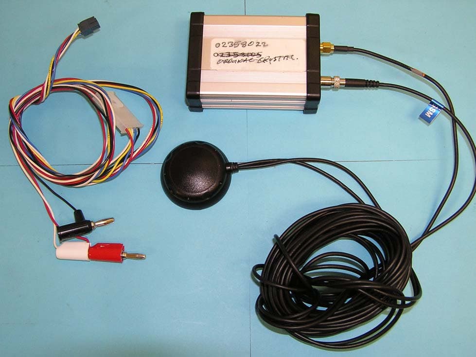
UQUMT0506
Feb 05, 2007GPS Tracking Device
Equipment Class
PCB - PCS Licensed Transmitter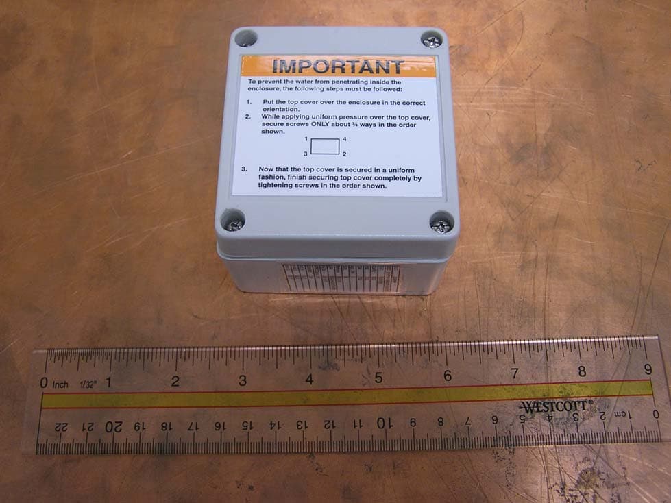
UQUAT0306
Jan 17, 2007GPS Tracking Device
Equipment Class
PCB - PCS Licensed Transmitter