UQUMT0506GPS Tracking Device
Columbus Nova Technology Group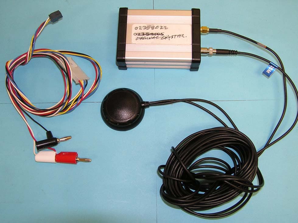
Click to zoom
Application Details
- Equipment Class
- PCB - PCS Licensed Transmitter
- Date of Grant
- Feb 05, 2007
- Application Purpose
- Original Equipment
- Date of Application
- Feb 05, 2007
- Equipment Note
- GPS Tracking Device
- Frequency Range
- 1850.20000000 - 1909.80000000
- Country
- United States
Documents & Files
Document Text
Text extracted from the exhibit documents filed with the FCC. Open a document above to read the original.
Users Manual
Page 1 of 23 MiniTrac GPRS Dual- Band Automatic Vehicle Locator (850/1900 MHz) Model: MT0505KE Owners Manual & Reference Guide © by Columbus Nova Technology Group, LLC All rights reserved — The Specifications and information regarding the products in this manual are subject to change without notice. All statements, information, and recommendations in this manual are believed to be accurate but are represented without warranty of any kind, express or implied. Users must take full responsibility for their applications of any Products. Reproduction of the contents of this manual, in whole or in part, without written permission of Columbus Nova Technology Group, LLC, is prohibited . January 2007 Page 2 of 23 Important! Before installing, turning on or operating the NovaTracker MiniTrac Unit, ensure compliance with all safety regulations. ! Page 3 of 23 INDEX Introduction 4 Hardware Installation 6 Operation 10 Specifications 12 Product Information 14 Antennas 15 Event Codes 16 Message Format 20 Regulation 22 Trouble Shooting Guide 23 Page 4 of 23 Introduction CNTG’s NovaTracker™ MiniTrac Unit system provides a very low cost but powerful solution for automatic vehicle location and other GPS tracking applications. It combines GPS technology with GSM cell phone networks, and is designed for multiple automotive applications such as vehicle tracking, monitoring, remote control, and GPS data logging. The MiniTrac works with any private or public IP network architecture. The unit comes standard with power and ground, ignition on/off, and GPS and GSM antenna (50 ohm) inputs and optionally one other digital input and one zero to +12V analog input. The MiniTrac is an event driven unit, messages are sent based on events. It records time, speed, distance, position and I/O status. Event thresholds are user programmable using the NovaTracker MapTrac client software or any IP based network. Features • GSM and GPS LED indications • Vehicle position, speed, direction, date, time, event, status • Compact, lightweight, and rugged • Remote Configuration and Firmware upgrade • Easy to install • Solid state design • Accepts standard SIM card • Geo-Fencing • 2 Digital Inputs (1 reserved for ignition on/off) • Data logger ready device with 4MB internal flash memory Event Triggers • Pre-set time interval • Pre-set distance interval • I/O status change (e.g. Ignition On or Off) Page 5 of 23 • Pre-set Speed • Geo-fence boundaries (optional) GPRS worldwide coverage is divided into 900/1800 and 850/1900 band. The NovaTracker™ MB is suitable for the USA, Canada, Mexico, and countries in Central and South America (except Brazil). The unit is delivered without a SIM card. A GPRS compatible SIM card is required to activate the unit. GPRS works through SMS (Short Message Service), commonly known as Text Messaging Service. A registered SIM card must be place into the MiniTrac SIM cardholder to allow reporting over the GPRS cellular data network SIM cards can be purchased and registered through your local GPRS carrier. The NovaTracker™ MiniTrac can collect data without the SIM card. Up to 4000 points of data can be stored. However, to retrieve this data, the unit must be powered down, the SIM card installed, and then powered on. The only other requirement for operation is an ignition ON/OFF signal and a 12V- 30V DC power source such as a car / truck's power supply or battery. Before installing the NovaTracker™ MiniTrac Unit: Please make sure that you have a SIM card that satisfies the following requirements: • Caller ID from your GPRS service provider allowed • Short Message Service (SMS) activated and supported by your GPRS service provider and activated • All PIN protection is removed Page 6 of 23 Hardware Installation The standard installation of the NovaTracker™ MiniTrac requires connection to a constant power supply (+V and GND), a switched power indicator (Ignition on/off) and the placement of the GPS, GPRS antenna. Total installation time is often less than an hour. Optionally, a 2 nd digital in and an analog in can be placed at convenient locations in the vehicle and connected to sensors and vehicle controls. Connections are typically made by crimping connectors directly to the appropriate wires. However, these connections are not required. Only a constant power supply and a switched power indicator are required. The MiniTrac contains the system's primary electronic components. Always mount the main module in the vehicle's interior compartments, in a covert and secure location, ensuring that moisture, vibration and temperature extremes are minimized. Acceptable locations include behind the dash, behind the glove compartment, in the trunk, under the seat or other interior panels. Important! The unit should be powered off before inserting the SIM card, connecting antennas, and inputs. Connect the unit’s ground (black) wire to vehicle ground first. Otherwise, an electrical short may occur and damage the unit Page 7 of 23 GPS/GPRS Dual Mode Antenna Installation Dual Mode Internal GSM/GPS Antenna When mounting the antenna, please consider the following: • The view of the sky must be as wide as possible • The field of view must not be obscured by any cable or metallic object (including windshield wipers, front windscreens with heating, UV filters or metallic tints) • The active side of the antenna (bottom of the antenna on stick- on models) should point towards the field of view Considering these points, either the GPS antenna should be mounted under a window, normally the front or rear screen, as these generally provide the maximum view of the sky. Antenna Installation Guidelines • Antenna must be mounted securely. • RF connectors must be properly connected to the RF cable. Be sure to use proper crimping tools. • Use a good quality low loss cable as provided • Mount GPS antennas where they will see the most sky • Mount antennas in areas with enough space for a ground plane. • Do not mount antennas too close to another antenn…
Text truncated - open the document above for the full version.
Cover Letter(s)
Federal Communication Commission Equipment Authorization Division, Application Processing Branch 7435 Oakland Mills Road Columbia, MD 21048 Date: January 2, 2007 To Whom It May Concern: Pursuant to Paragraphs §0.457 and 0.459 of the Commission’s Rules (47 C.F.R.) and Section §552(b)(4) of the Freedom of Information Act, Columbus Nova Technology Group, LLC DBA NovaTracker requests confidentiality for the following products: FCC ID Number Product Title/Model UQUMT0506 MiniTrac For the product stated above, we request that the following information be held confidential: 1) Electrical Schematics of the Circuitry 2) Block Diagram 3) Parts List 4) Tune-up Procedure 5) Operational Description No other items submitted as part of the equipment authorization filing process are deemed confidential. The above exhibits contain Columbus Nova Technology Group, LLC DBA NovaTracker trade secrets and proprietary information that could be of benefit to our competitors regarding the design of our mobile handset. This material is not customarily available to the general public and we request that it be withheld from public inspection. If you have any questions, please feel free to contact me at the address shown below. Sincerely, Dave Leis, President 11 Commerce Drive, Lobby Floor Cranford, NJ 07016 Tel: 908-272-0114
External Photos
PAGE 1 OF 9 EUT External Photos FOR: GPS Tracking Device MODEL #: MT0505KE Columbus Nova Technology Group, LLC DBA NovaTracker 11 Commerce Drive. Lobby Floor Cranford, NJ 07016 USA FCC ID: UQUMT0506 TEST REPORT #: NOVA1_003_06002_FCC22_24 DATE: 2007-1-30 Bluetooth Qualification Test Facility (BQTF) FCC listed# 101450 IC recognized # 3925 CETECOM Inc. 411 Dixon Landing Road Milpitas, CA 95035 U.S.A. Phone: + 1 (408) 586 6200 Fax: + 1 (408) 586 6299 E-mail: [email protected] http://www.cetecom.com CETECOM Inc. is a Delaware Corporation with Corporation number: 2113686 Board of Directors: Dr. Harald Ansorge, Dr. Klaus Matkey, Hans Peter May © Copyright by CETECOM PAGE 2 OF 9 Table of Contents .................................................................................................................................... 3 1ASSESSMENT .............................................................................................................. 4 2EUT EXTERNAL PHOTOS 2.1 .............................................................................................................................. 4 EUT TOP VIEW 2.2 ............................................................................................................................. 5 EUT SIDE VIEW 2.3 ............................................................................................................................. 6 EUT SIDE VIEW 2.4 ............................................................................................................................. 7 EUT SIDE VIEW 2.5 ...................................................................................................................... 9 EUT BOTTOM VIEW This report shall not be reproduced except in full without the written approval of: CETECOM, Inc. PAGE 3 OF 9 1 Assessment The following is in compliance with the applicable criteria specified in FCC rules Parts 2, 22 and 24 of Title 47 of the Code of Federal Regulations and in compliance with the applicable criteria specified in Industry Canada rules RSS132 and RSS133. Company Description Model # Columbus Nova Technology Group, LLC DBA NovaTracker GPS Tracking Device MT0505KE Date: 1/30/2007 Name: Peter Mu Title: Project Engineer Company: Cetecom Inc. Address: 411 Dixon Landing Rd, Milpitas, CA 95035, USA Phone: +1 408 586 6221 Email: [email protected] This report shall not be reproduced except in full without the written approval of: CETECOM, Inc. PAGE 4 OF 9 2 EUT EXTERNAL PHOTOS 2.1 EUT Top View This report shall not be reproduced except in full without the written approval of: CETECOM, Inc. PAGE 5 OF 9 2.2 EUT Side View This report shall not be reproduced except in full without the written approval of: CETECOM, Inc. PAGE 6 OF 9 2.3 EUT Side View This report shall not be reproduced except in full without the written approval of: CETECOM, Inc. PAGE 7 OF 9 2.4 EUT Side View This report shall not be reproduced except in full without the written approval of: CETECOM, Inc. PAGE 8 OF 9 2.5 EUT Side View This report shall not be reproduced except in full without the written approval of: CETECOM, Inc. PAGE 9 OF 9 2.6 EUT Bottom View This report shall not be reproduced except in full without the written approval of: CETECOM, Inc.
ID Label/Location Info
____________________________________________________________ NOVA TRACKER – PROPRIETARY Page 1 of 1 Title: PRODUCT LABEL MiniTrac 2.5 INCH 1 INCH IMEI / SERIAL : MODEL: MT0505KE PRODUCT : MT-90001R-1A FCC ID: UQUMT0506 FIRMWARE: MINI TRAC - LABEL AssetTrac 2.5 INCH 1 INCH IMEI / SERIAL : MODEL: AT0303KE PRODUCT: AT-90001R-1A FCC ID: UQUAT0306 FIRMWARE: ASSET TRAC - LABEL
Internal Photos
PAGE 1 OF 6 EUT Internal Photos FOR: GPS Tracking Device MODEL #: MT0505KE Columbus Nova Technology Group, LLC DBA NovaTracker 11 Commerce Drive. Lobby Floor Cranford, NJ 07016 USA FCC ID: UQUMT0506 TEST REPORT #: NOVA1_003_06002_FCC22_24 DATE: 2007-1-3 Bluetooth Qualification Test Facility (BQTF) FCC listed# 101450 IC recognized # 3925 CETECOM Inc. 411 Dixon Landing Road Milpitas, CA 95035 U.S.A. Phone: + 1 (408) 586 6200 Fax: + 1 (408) 586 6299 E-mail: [email protected] http://www.cetecom.com CETECOM Inc. is a Delaware Corporation with Corporation number: 2113686 Board of Directors: Dr. Harald Ansorge, Dr. Klaus Matkey, Hans Peter May © Copyright by CETECOM PAGE 2 OF 6 Table of Contents .................................................................................................................................... 3 1ASSESSMENT ............................................................................................................... 4 2EUT INTERNAL PHOTOS This report shall not be reproduced except in full without the written approval of: CETECOM, Inc. PAGE 3 OF 6 1 Assessment The following is in compliance with the applicable criteria specified in FCC rules Parts 2, 22 and 24 of Title 47 of the Code of Federal Regulations and in compliance with the applicable criteria specified in Industry Canada rules RSS132 and RSS133. Company Description Model # Columbus Nova Technology Group, LLC DBA NovaTracker GPS Tracking Device MT0505KE Date: 1/10/2007 Name: Peter Mu Title: Project Engineer Company: Cetecom Inc. Address: 411 Dixon Landing Rd, Milpitas, CA 95035, USA Phone: +1 408 586 6221 Email: [email protected] This report shall not be reproduced except in full without the written approval of: CETECOM, Inc. PAGE 4 OF 6 2 EUT INTERNAL PHOTOS 2.1 MT0505KE Internal PCB Top Side This report shall not be reproduced except in full without the written approval of: CETECOM, Inc. PAGE 5 OF 6 2.2 MT0505KE Internal PCB Bottom Side This report shall not be reproduced except in full without the written approval of: CETECOM, Inc. PAGE 6 OF 6 2.3 Internal Picture Siemens MC56 Module This report shall not be reproduced except in full without the written approval of: CETECOM, Inc.
RF Exposure Info
FCC-ID UQUMT0506 IC-ID (Industry Canada) PREDICTION OF MPE AT A GIVEN DISTANCE Calculations can be made to predict RF field strength and power density levels around typical RF sources using the general equations (3) and (4) on page 19 of the following FCC document: “OET Bulletin 65, Edition 97-01 - Evaluating Compliance with FCC Guidelines for Human Exposure to Radio frequency Electromagnetic Fields”. These equations are generally accurate in the far field of an antenna but will over predict power density in the near field, where they could be used for making a “worst case” prediction. S = PG/4πR 2 (3) Where S = power density (in appropriate units, e.g. mW/cm 2 ) P = power input to the antenna (in appropriate units e.g. mW) G = power gain of the antenna in the direction of interest relative to the isotropic radiator R = distance to the center of radiation of the antenna (appropriate units e.g. cm) or, S = EIRP/4πR 2 (4) Where EIRP = Equivalent Isotropically radiated power General Limits: §1.1307 Cellular Radiotelephone Service (subpart H of part 22) Non-building-mounted antennas: height above ground level to lowest point of antenna < 10 m and total power of all channels > 1000 W ERP (1640 W EIRP) §1.1307 Personal Communications Services (part 24) Broadband PCS (subpart E): non-building-mounted antennas: height above ground level to lowest point of antenna < 10 m and total power of all channels > 2000 W ERP (3280 W EIRP) §1.1310 LIMITS FOR MAXIMUM PERMISSIBLE EXPOSURE (MPE) (B) Limits for General Population/Uncontrolled Exposure 300–1500 MHz: f/1500 mW/cm² 1500–100,000 MHz: 1.0 mW/cm² §2.1091 No routine evaluation required when the device ...operate at frequencies of 1.5 GHz or below and their effective radiated power (ERP) is 1.5 watts or more, or if they operate at frequencies above 1.5 GHz and their ERP is 3 watts or more. FCC-ID UQUMT0506 IC-ID (Industry Canada) §24.232 (a) Base stations are limited to 1640 watts peak equivalent isotropically radiated power (e.i.r.p.) with an antenna height up to 300 meters HAAT. b) Mobile/portable stations are limited to 2 watts e.i.r.p. peak power, ... §22.913 (a) Maximum ERP. The effective radiated power (ERP) of base transmitters and cellular repeaters must not exceed 500 Watts. The ERP of mobile transmitters and auxiliary test transmitters must not exceed 7 Watts. The table below is excerpted from Table 1B of 47 CFR 1.1310 titled “Limits for Maximum Permissible Exposure (MPE), Limits for General Population/Uncontrolled Exposure” Frequency Range (MHz) Power Density (mW/cm 2 ) 300 -1500 f/1500 1500 - 100000 1.0 Prediction for Part 22 Maximum radiated power EIRP: 28.87dBm (771mW) @ 848.8MHz Lowest limit for 850 MHz fixed operations (@20cm) where no routine evaluation is required is § 1.1310: (f/1500)mW/cm 2 =0.5659 mW/cm 2 Calculated at distance of 20cm: Power density = 771 / (4 x pi x 20 2 ) = 0.1534 mW/cm 2 Result: Configuration complies with rules as power density is below MPE limit. Prediction for Part 24 Maximum radiated power EIRP: 21.81dBm (152mW) @1880MHz Lowest limit for 1900 MHz fixed operations (@20cm) where no routine evaluation is required is § 1.1310 : 1 mW/cm 2 Calculated at distance of 20cm: Power density = 152 / (4 x pi x 20 2 ) = 0.0302mW/cm 2 Result: Configuration complies with rules as power density is below MPE limit. FCC-ID UQUMT0506 IC-ID (Industry Canada) Date: 1/30/2007 Name: Peter Mu Title: Project Engineer Company: Cetecom Inc. Address: 411 Dixon Landing Rd, Milpitas, CA 95035, USA Phone: +1 408 586 6221 Email: [email protected]
Test Report
CETECOM ICT Services GmbH Radio Satellite Communication Untertürkheimer Straße 6-10 . D-66117 SaarbrückenTelefon: +49 (0)681 598-9100Telefax: -9075 RSC11Issued test report consists of 97 pagesPage 1 (97) BLUETOOTH TM is a trademark owned by Bluetooth SIG, Inc. and licensed to CETECOM Recognized by the Federal Communications Commission Anechoic chamber registration no.: 90462 (FCC) Anechoic chamber registration no.: 3463 (IC) TCB ID: DE 0001 Accredited by the German Accreditation Council DAR–Registration Number TTI–P–G 166/98 Independent ETSI compliance test house ETSI Accredited Bluetooth™ Test Facility (BQTF) Test report no.: 2_3450-01-01/03 FCC Part 24/22/15 MC56 FCC ID: QIPMC56 IC: 267W-MC56 CETECOM – ICT Services GmbH Untertürkheimerstr. 6-10 66117 Saarbrücken, Germany Telephone: + 49 (0) 681 / 598-0 Fax: + 49 (0) 681 / 598-9075 CETECOM ICT Services GmbH Test report no..: 2_3450-01-01/03Issue Date: 2003-12-12Page 2 (97) Table of Contents 1 General information 1.1 Notes 1.2 Testing laboratory 1.3 Details of applicant 1.4 Application details 1.5 Test item 1.6 Test standards 2 Technical test 2.1 Summary of test results 2.2 Test report 1 General information 1.1 Notes The test results of this test report relate exclusively to the test item specified in 1.5. The CETECOM ICT Services GmbH does not assume responsibility for any conclusions and generalizations drawn from the test results with regard to other specimens or samples of the type of the equipment represented by the test item. The test report may only be reproduced or published in full. Reproduction or publication of extracts from the report requires the prior written approval of the CETECOM ICT Services GmbH. 1.2Testing laboratory CETECOM ICT Services GmbH Untertürkheimer Straße 6 - 10 66117 Saarbrücken Germany Telefone: + 49 681 598 - 9100 Telefax : + 49 681 598 - 9075 E-mail: [email protected] Internet: www.cetecom-ict.de Accredited testing laboratory The test laboratory (area of testing) is accredited according to DIN EN ISO/IEC 17025. DAR registration number: TTI-P-G-166/98 Listed by: Federal Communications Commission (FCC) Identification/Registration No : 90462 Accredited Bluetooth TM Test Facility (BQTF) BLUETOOTH TM is a trademark owned by Bluetooth SIG, Inc. and licensed to CETECOM CETECOM ICT Services GmbH Test report no..: 2_3450-01-01/03Issue Date: 2003-12-12Page 3 (97) 1.3Details of applicant Name : Siemens AG Street : Siemensdamm 50 City : D-13629 Berlin Country : Germany Telephone : +49 (0)30 386-0 Telefax : +49 (0)30 386-366-56 Contact : Mr. Hussein Halawi Telephone : +49 (0)30 386-302-11 e-mail: [email protected] 1.4Application details Date of receipt of application : 2003-12-03 Date of receipt of test item : 2003-12-03 Date of test : 2003-12-03 1.5Test item Type of equipment : Tripple Band GSM/PCS Module (850/1800/1900 MHz) Type designation:MC56 Manufacturer:applicant Street: City: Country: Serial numbers:IMEI :004999.00.273656.01, Ser Nr. 273056 Additional information: : Frequency:1850.2 – 1909.8 MHz and 824.2 – 848.8 MHz Type of modulation:300KGXW / 300KG7W Number of channels :300 (PCS1900) and 125 (PCS850) Antenna:Coax adapter for use with external antennas, here a standard car magnet antenna Power supply:3,8V DC via connector Output power GSM 850:cond.: 33.0 dBm Peak , ERP: 24.8 dBm (Burst); EIRP: 26.9 dBm (Burst) Output power GSM 1900 :cond : 28.7 dBm Peak , ERP: 25.3 dBm (Burst); EIRP: 27.4 dBm (Burst) Type of equipment:Temperature range : -30°C - +60°C FCC – ID:QIPMC56 IC :267W-MC56 Hardware:S30880-S8365-A100(B1) Software:026 1.6Test standards: FCC Part 24, 22 FCC Part 15 CETECOM ICT Services GmbH Test report no..: 2_3450-01-01/03Issue Date: 2003-12-12Page 4 (97) 2 Technical test For Part 24/22 we use the substitution method ( TIA/EIA 603). All measurements in this report are done in GSM mode. Device is able to transmit data in GPRS mode also. But because the current measurements are performed in PEAK mode no other results from GPRS mode are possible. The only different is the modulation average power, which is 3 dB higher (by using 2 timeslots in the Up-link (GPRS mode 10)). Remarks: Test setup :The sample was tested in a special test board to bring power to the card and connect RF over a special coax connector to a standard coax adapter. For radiated measurements we used a standard magnetic dualband mobile antenna mounted on a metal plate to get comparative results. No deviations from the technical specification(s) were ascertained in the course of the tests performed. FINAL VERDICT: PASS Technical responsibility for area of testing : 2003-12-15RSC 8414 Ames H. DateSectionNameSignature Technical responsibility for area of testing : 2003-12-15RSC8412Hausknecht D. DateSectionNameSignature CETECOM ICT Services GmbH Test report no..: 2_3450-01-01/03Issue Date: 2003-12-12Page 5 (97) 2.2Test report TEST REPORT Test report no. : 2_3450-01-01/03 CETECOM ICT Services GmbH Test report no..: 2_3450-01-01/03Issue Date: 2003-12-12Page 6 (97) TEST REPORT REFERENCE LIST OF MEASUREMENTS PARAMETER TO BE MEASURED PAGE Part PCS 1900 POWER OUTPUT SUBCLAUSE § 24.2328 FREQUENCY STABILITY SUBCLAUSE § 24.23510 AFC FREQ ERROR vs. VOLTAGE11 AFC FREQ ERROR vs. TEMPERATURE11 EMISSIONS LIMITS SUBCLAUSE §24.23813 RECEIVER SPURIOUS RADIATION SUBCLAUSE § 15.10922 CONDUCTED SPURIOUS EMISSIONS27 BLOCK EDGE COMPLIANCE FOR BLOCK A AND C36 OCCUPIED BANDWIDTH SUBCLAUSE §2.98938 PART PCS 850 POWER OUTPUT SUBCLAUSE § 22.91345 FREQUENCY STABILITY SUBCLAUSE § 22.35547 AFC FREQ ERROR vs. VOLTAGE48 AFC FREQ ERROR vs. TEMPERATURE48 EMISSIONS LIMITS SUBCLAUSE §22.91750 RECEIVER SPURIOUS RADIATION SUBCLAUSE § 15.10959 CONDUCTED SPURIOUS EMISSIONS63 BLOCK EDGE REQUIREMENTS72 OCCUPIED BANDWIDTH SUBCLAUSE §2.98974 EMISSION LIMITATIONS FOR CELLULAR SUBCLAUSE §22.917(F)81 CETECOM ICT Services GmbH Test report no..: 2_3450-01-01/03Issue Date: 2003-12-12Page 7 (97) TEST EQUIPMENT AND ANCILLARIES USED FOR TESTS90 Test site92 CETECOM ICT Services Gmb…
Text truncated - open the document above for the full version.
Test Report
Bluetooth Qualification Test Facility (BQTF) FCC listed# 101450 IC recognized # 3925 CETECOM Inc. 411 Dixon Landing Road Milpitas, CA 95035 U.S.A. Phone: + 1 (408) 586 6200 Fax: + 1 (408) 586 6299 E-mail: [email protected] http://www.cetecom.com CETECOM Inc. is a Delaware Corporation with Corporation number: 2113686 Board of Directors: Dr. Harald Ansorge, Dr. Klaus Matkey, Hans Peter May © Copyright by CETECOM FCC Test Report FCC Part 22,24 / RSS 132,133 FOR: GPS Tracking Device MODEL #: MT0505KE Columbus Nova Technology Group, LLC DBA NovaTracker 11 Commerce Drive. Lobby Floor Cranford, NJ 07016 USA FCC ID: UQUMT0506 TEST REPORT #: NOVA1_003_06002_FCC22_24 DATE: 2007-1-30 Test Report #: NOVA1_003_06002_FCC22_24 Date of Report: 2007-1-30 Page 2 of 48 This report shall not be reproduced except in full without the written approval of: CETECOM, Inc. Table of Contents 1 ASSESSMENT .....................................................................................................................................4 EMC & Radio.........................................................................................................................................4 1.1 ADMINISTRATIVE DATA.................................................................................................................5 1.1.1 Identification of the Testing Laboratory Issuing the EMC Test Report .................................5 1.1.2 Identification of the Client......................................................................................................5 1.1.3 Identification of the Manufacturer .........................................................................................5 1.2 EQUIPMENT UNDER TEST (EUT) ....................................................................................................5 1.2.1 Specification of the Equipment under Test .............................................................................6 1.2.2 Identification of the Equipment Under Test (EUT) ................................................................6 1.2.3 Identification of Accessory equipment ...................................................................................6 2 SUBJECT OF INVESTIGATION......................................................................................................7 3 MEASUREMENTS..............................................................................................................................8 3.1 RF POWER OUTPUT........................................................................................................................8 3.1.1 FCC 2.1046 Measurements required: RF power output........................................................8 3.1.2 Limits: ....................................................................................................................................8 3.1.2.1 FCC 22.913 (a) Effective radiated power limits. ...............................................................8 3.1.2.2 FCC 24.232 (b)(c) Power limits. ........................................................................................8 3.1.3 Conducted Output Power Measurement procedure:..............................................................8 3.1.4 Radiated Output Power Measurement procedure:.................................................................9 3.1.5 ERP Results 850 MHz band: ................................................................................................10 3.1.6 EIRP Results 1900 MHz band:.............................................................................................10 3.2 OCCUPIED BANDWIDTH/EMISSION BANDWIDTH.........................................................................11 3.2.1 FCC 2.1049 Measurements required: Occupied bandwidth................................................11 3.2.2 Occupied / emission bandwidth measurement procedure:...................................................11 3.2.3 Occupied / Emission bandwidth results 850 MHz band: .....................................................12 3.3 FREQUENCY STABILITY................................................................................................................12 3.3.1 Limit .....................................................................................................................................12 3.3.2 FREQUENCY STABILITY (GSM-850) ................................................................................13 3.3.3 FREQUENCY STABILITY (PCS-1900) ...............................................................................13 3.4 SPURIOUS EMISSIONS CONDUCTED..............................................................................................13 3.4.1 FCC 2.1051 Measurements required: Spurious emissions at antenna terminals. ...............13 3.4.2 Limits: ..................................................................................................................................13 3.4.2.1 FCC 22.917 Emission limitations for cellular equipment. ..............................................13 3.4.2.2 FCC 24.238 Emission limitations for Broadband PCS equipment. ................................14 3.4.3 Conducted out of band emissions measurement procedure: ................................................14 3.5 SPURIOUS EMISSIONS RADIATED.................................................................................................15 3.5.1 FCC 2.1053 Measurements required: Field strength of spurious radiation........................15 3.5.2 Limits: ..................................................................................................................................15 3.5.2.1 FCC 22.917 Emission limitations for cellular equipment. ..............................................15 3.5.2.2 FCC 24.238 Emission limitations for Broadband PCS equipment. ................................16 3.5.3 Radiated out of band measurement procedure: ........................................…
Text truncated - open the document above for the full version.
Test Setup Photos
PAGE 1 OF 6 Test Setup Photos FOR: GPS Tracking Device MODEL #: MT0505KE Columbus Nova Technology Group, LLC DBA NovaTracker 11 Commerce Drive. Lobby Floor Cranford, NJ 07016 USA FCC ID: UQUMT0506 TEST REPORT #: NOVA1_003_06002_FCC22_24 DATE: 2007-1-26 Bluetooth Qualification Test Facility (BQTF) FCC listed# 101450 IC recognized # 3925 CETECOM Inc. 411 Dixon Landing Road Milpitas, CA 95035 U.S.A. Phone: + 1 (408) 586 6200 Fax: + 1 (408) 586 6299 E-mail: [email protected] http://www.cetecom.com CETECOM Inc. is a Delaware Corporation with Corporation number: 2113686 Board of Directors: Dr. Harald Ansorge, Dr. Klaus Matkey, Hans Peter May © Copyright by CETECOM PAGE 2 OF 6 Table of Contents .................................................................................................................................... 3 1ASSESSMENT ..................................................................................................................... 4 2TEST SETUP PHOTOS This report shall not be reproduced except in full without the written approval of: CETECOM, Inc. PAGE 3 OF 6 1 Assessment The following is in compliance with the applicable criteria specified in FCC rules Parts 2, 22 and 24 of Title 47 of the Code of Fed…
Text truncated - open the document above for the full version.
Contact Information
Applicant
Tracy Kan(Regulatory Engineer)
Test Firm
cetecom advanced GmbHGerald Schmidt
Technical Specifications
| # | Rule Parts | Frequency Range | Power Output | Emission | Tolerance |
|---|---|---|---|---|---|
| 2 | 24E | 1.85 GHz - 1.91 GHz | 152.00 mW | 300KGXW | 0.02 ppm |
Other Applications from Columbus Nova Technology Group
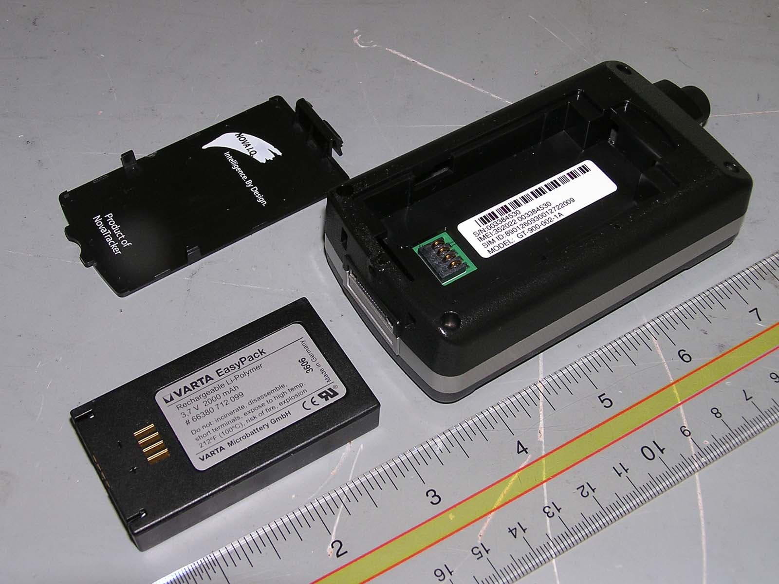
UQUGT900001
Nov 06, 2007GPS Tracking Device
Equipment Class
PCE - PCS Licensed Transmitter held to ear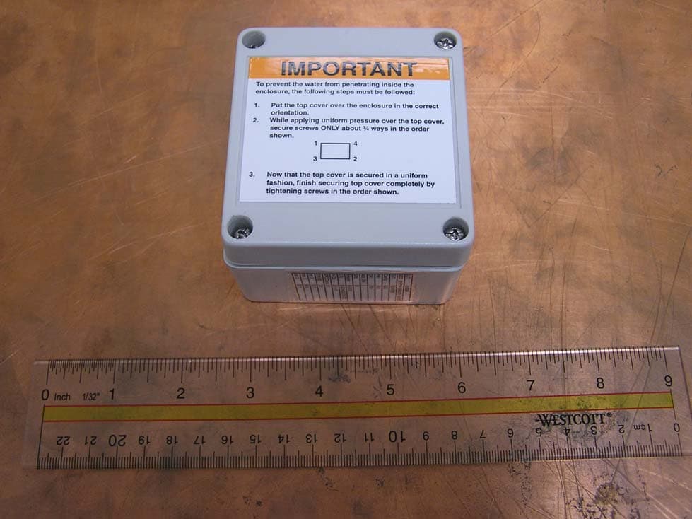
UQUAT0306
Jan 17, 2007GPS Tracking Device
Equipment Class
PCB - PCS Licensed Transmitter