UQY-SW1500RFID/Barcode Reader
WaveMark, Inc.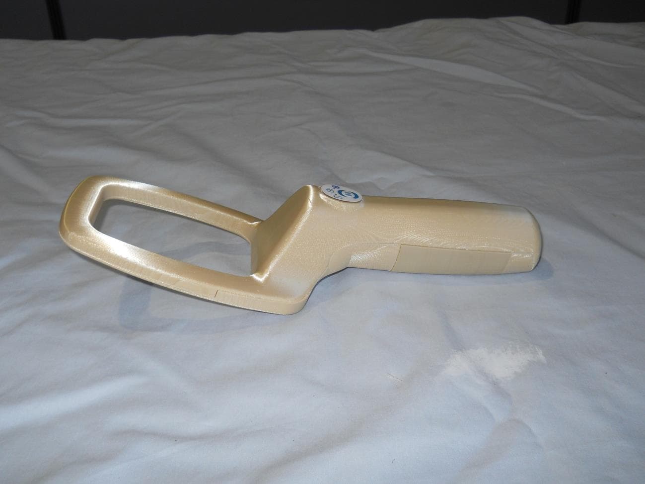
Click to zoom
Application Details
- Equipment Class
- DXX - Part 15 Low Power Communication Device Transmitter
- Date of Grant
- Sep 16, 2013
- Application Purpose
- Original Equipment
- Date of Application
- Sep 16, 2013
- Equipment Note
- RFID/Barcode Reader
- Frequency Range
- 13.56000000 - 13.56000000
- Company
- WaveMark, Inc.
- Country
- United States
Documents & Files
Document Text
Text extracted from the exhibit documents filed with the FCC. Open a document above to read the original.
Users Manual
WaveMark Document 97-0009 Rev B WaveMark SmartWand SW1500 RFID/Barcode Reader The WaveMark SmartWand SW1500 Portable RFID/Barcode Reader Kit comprises the following components: 1. WaveMark SmartWand (WaveMark 01-0029-R) 2. Power Supply/charger (WaveMark 90-0094-R) 3. International Plug kit for Power Supply (WaveMark 90-0095-R) 4. Tether strap (WaveMark 90-0096-R) 5. Software (please see your WaveMark representative for appropriate software applications) The WaveMark SmartWand is a battery-operated RFID/Barcode reader and is equipped with a rechargeable battery pack that is capable of running the reader for one 8-hour shift (50% RFID duty-cycle) on a full charge. The battery pack is based upon Lithium Ion cells, nominally 7.4VDC. The SmartWand battery pack is shipped to the customer pre-installed in the WaveMark SmartWand and is partially charged when shipped. The WaveMark SmartWand has a power slide switch on the back. WaveMark SmartWand Power Supply Tether Plug Kit Power slide switch WaveMark Document 97-0009 Rev B When the switch is in the left position, the WaveMark SmartWand is off. Slide the switch to the right to turn it on. A green or orange power light on the control panel will light if the device is on: Steady Green power light: WaveMark SmartWand is charged to over 50%. Steady Orange power light: WaveMark SmartWand is charged to between 20% and 50%. Flashing Orange power light: WaveMark SmartWand is operating on low charge (less than 20%). The control panel has 3 other lights: Bluetooth® blue light (solid blue when device is paired to a host, brief flash when communication to host is in process). Yellow RFID light (solid yellow when RFID reader function is operational and seeking RFID tags, brief flash when RFID tags are read). Power Light Bluetooth® Light RFID Light WaveMark Document 97-0009 Rev B Yellow Barcode light (solid yellow when Barcode function is operational; in this state, the Barcode button can be used to read a Barcode. When the yellow light is not lit, this button performs no function). Use only the charger that is supplied with the WaveMark SmartWand (WaveMark part number 90- 0094-R charger and 90-0095-R international plug kit). Select the plug that is appropriate for the electrical receptacles in your area. The WaveMark SmartWand should be charged with the power slide switch in the off (left) position. When charging, the power light will be flashing green. When fully charged, the power light will be solid green. Do not use the WaveMark SmartWand to read RFID tags or Barcodes while it is charging. A full charge will take approximately 6 hours, but shorter charging cycles will provide a partial charge. It is OK to leave the charger connected to the WaveMark SmartWand for extended periods of time, as long as the power switch is “off”. The charger is a multi-stage “smart” charger designed to sense the condition of the battery and provide protection against over- and under- charging. Barcode Light Install Plug Select Plug Style Remove Filler WaveMark Document 97-0009 Rev B The WaveMark SmartWand has a USB-mini-B port adjacent to the charging port. This USB port is not currently supported for any user accessible purpose. It also will not successfully charge the battery in the WaveMark SmartWand. Do not plug a USB cable into this port. When you are ready to use the WaveMark SmartWand to read RFID tags or Barcodes, disconnect the charger, slide the power switch to the “on” position, and follow the instructions of the Host software application that you are using. The SmartWand battery pack is customer replaceable. This should only be necessary after approximately 300 charging cycles when the operating time is no longer sufficient. Use only battery packs that are supplied by WaveMark (part number 04-0098-R). Replacement instructions are supplied with the purchase of a spare battery. Charging port USB port WaveMark Document 97-0009 Rev B Specifications Length: 333 mm Width: 115 mm Height: 76 mm Weight: 400 grams Operating Temperature Range: 0 degrees C to +40 degrees C Charging Voltage: 12 V DC nominal Charging Current: 0.5 A Max RFID Tag Types Supported: HF, ISO 15693, 13.56 MHz Maximum Read Speed: 50 RFID tags/second Bluetooth: Smart Ready, Bluetooth® 4.0 Maximum Bluetooth Pairing Range: 50 meters Barcode Reader: 1-D + 2-D Imager WaveMark Document 97-0009 Rev B Notice of FCC Compliance FCC ID UQY-SW1500 NOTE: This equipment has been tested and found to comply with the limits for a Class A digital device, pursuant to Part 15 of the FCC Rules. These limits are designed to provide reasonable protection against harmful interference when the equipment is operated in a commercial environment. This equipment generates, uses, and can radiate radio frequency energy and, if not installed and used in accordance with the instruction manual, may cause harmful interference to radio communications. Operation of this equipment in a residential area is likely to cause harmful interference in which case the user will be required to correct the interference at his own expense. Changes or modifications not expressly approved by WaveMark, Inc. could void the user’s authority to operate the equipment. Warning! FCC Radiation Exposure Statement: This portable equipment with its antenna complies with the FCC’s RF radiation exposure limits set forth for an uncontrolled environment. To maintain compliance follow the instructions below: 1) This transmitter must not be co-located or operating in conjunction with any other antenna or transmitter. 2) Avoid direct contact to the antenna, or keep contact to a minimum while using this equipment. FCC Compliance statement for Bluetooth® Radio: This device contains FCC ID: PVH0946 This device complies with Part 15 of the FCC Rules. Operation is subject to the following two conditions; (1) this device may not cause harmful interference, and (2) this device must accept any interference received, including interference that may cause undesired ope…
Text truncated - open the document above for the full version.
ID Label/Location Info
.54 2.23 R.05 This device complies with Part 15 of the FCC Rules. Operation is subject to the following two conditions: (1) this device may not cause harmful interference, and (2) this device must accept any interference received, including interference that may cause undesired operation. NOTES: MATERIAL: MYL, WHT-OPAQ, T/C249(20X27 - 2 MIL, V-23, 90# PFW 1. MYL,MAT,#OM100CM(27"X750' - 1MIL,L44 ADH,42#PP-8 ALL MATERIALS AND MANUFACTURING PROCESSES MUST BE 2. ROHS COMPLIANT. MATERIAL AND ROHS CERTIFICATE OF COMPLIANCE REQUIRED 3. WITH PART DELIVERY WaveMark SmartWand Model: SW1500 FCC ID: UQY-SW1500 CONTAINS: FCC ID PVH0946 12VDC --- 0.5A ROHS COMPLIANT www.wavemark.com made in USA SN: SW15XXX SERIAL NUMBER TO BE SEQUENCED. START NO. TO BE REFERENCED ON P.O. REVISIONS ZONEREV.DESCRIPTIONDATEAPPROVED ARELEASE FOR PRODUCTION08/01/13JB .54 2.23 R.05 DOC NO. A 1 1 A 2 2 3 3 4 4 BB C C D D SIZE B REV STANDARD TOLERANCES .XX = .01 .XXX = .005 ANGLES = 1/2 ENGINEER DRAWN PROJECTION CONCENTRICITY .005 TIR ALL MACHINED SURFACES ALL SHARP EDGES .01-.02 THE INFORMATION CONTAINED IN THIS DRAWING IS THE PROPERTY OF WAVEMARK INC AND IS CONFIDENTIAL AND PROPRIETARY TO THE COMPANY. IT IS NOT TO BE COPIED OR REPRODUCED IN WHOLE OR IN PART UNLESS AUTHORIZED BY WAVEMARK INC. FRAC. = 1/32 OF APPROVALSDATE SHEET REV 91-0069-RA JB 10/24/08 1 1 2:1 A 1 DO NOT SCALE DRAWING UNLESS OTHERWISE SPECIFIED PROPRIETARY NOTICE ALL DIMENSIONS ARE IN INCHES ALL DIMENSIONS APPLY AFTER FINISH 63 MATERIAL: FINISH: TITLE DOC NO. SCALESHEET CHECKED FCC SMARTWAND LABEL ROHS One Monarch Drive, Littleton, MA 01460
Internal Photos
BT module
RF Exposure Info
RF Exposure Considerations for FCC ID: UQY-SW1500 Per FCC KDB 447498 D01 General RF Exposure Guidance v05 The 1-g and 10-g SAR test exclusion thresholds for 100 MHz to 6 GHz at test separation distances ≤ 50 mm are determined by (Eq.1) below: [(max. power of channel, including tune-up tolerance, mW)/(min. test separation distance, mm)] * [√f (GHz)] If result of Eq.1 is less than or equal to the exemption limits below, then corresponding SAR test is not required. SAR Test Configuration Exemption limit 1-g SAR Result of Eq.1 ≤ 3.0 10-g extremity SAR Result of Eq.1 ≤ 7.5 where; f(GHz) is the RF channel transmit frequency in GHz. Power and distance are rounded to the nearest mW and mm before calculation. The result is rounded to one decimal place for comparison. The test exclusions are applicable only when the minimum test separation distance is ≤ 50 mm and for transmission frequencies between 100 MHz and 6 GHz. When the minimum test separation distance is < 5 mm, a distance of 5 mm is applied to determine SAR test exclusion. For this device, the parameters for consideration are as follows: The closest distance from the Bluetooth antenna surface to the outside of the plastic is 0.29 inches ( = 7.3mm) according to applicant’s CAD design model. Minimum separation distance of 7mm is used for the calculation. Bluetooth output power used in the calculation is the highest peak conducted output power as listed on its grant (FCC ID: PVH0946). Maximum source‐based time averaged conducted output power would actually be far lower for a Bluetooth radio. Frequency (GHz) Maximum source- based time averaged conducted output power including tune- up tolerance (mW) Minimum separation distance (mm) Result of Eq. 1 Limit for 1-g SAR Limit for 10-g extremity SAR Verdict 2.450 11mW 7mm 2.46 3.0 7.5 Exempt from SAR Conclusion: Therefore device complies with FCC’s RF radiation exposure limits for general population without SAR evaluation.
Test Report
This test report applies only on equipment described hereafter. Proposal number: 200505-2686 Date.........................................: May 18 th ,2005 Location...................................: LCIE Laboratory - 38 VOIRON Performed by............................: Jacques LORQUIN Customer..................................: TAGSYS S.A. 180, Chemin de Saint Lambert 13821 La PENNE SUR HUVEAUNE FRANCE Product.....................................: L-P101 with AERO LI antenna L-P101 with LSA3 antenna Type of test..............................: Radiated and Conducted Emission Test Applied standards.....................: ANSI C63-4 (2003) 47 CFR Part 15 Subpart C CISPR 22 (2003) Result of tests........................: Radiated Emission : Comply Conducted Emission : Comply The reproduction of this test report is authorized only under its entire form. This report contents 1 pages. Written by.................................: Jacques LORQUIN Approved by : Jacques LORQUIN EMC TEST REPORT Nr 3420-FCC Nr 3420-FCC May 18th ,2005 page 2 /26 1. System test configuration 1.1. Justification The system was configured for testing in a typical fashion (as a customer would normally use it). 1.2. HARDWARE IDENTIFICATION: * Equipment Under Test (EUT): MEDIO L-P101 pn:SE11912A0 sn:T0519010A0 * Configuration: ÿ Antenne AEROLI: - Taille : 280x280x20mm - E/S : antenna connector BNC (coaxial cable with 6 ferrites) ÿ Antenne LSA3: - Taille : 440x360x25mm - E/S : antenna connector BNC (coaxial cable with 6 ferrites) ÿ RF transmitter : - Taille : 120x65x30mm - E/S : * Antenna connector SMA * USB port * power supply 12Vdc 1.3. Auxiliaries The FCC IDs for all equipment, more description of all cables used in the tested system are : Trade Mark – Model Number (Serial number) FCC ID Description Cable description L-P101 pn:SE119120A0* (sn: none) RFID reader Power cord unshielded. USB cable shielded Coaxial cable with 6 ferrites. XP model:MPP6US12-2 (sn: 0605) none AC/DC Power supply Power cord unshielded. RDI model Cl51-15 (sn: 0450203) none Personal computer with power supply Power cord unshielded. All other cable shielded. HP pn:C6410A (sn: MY97619) D.O.C. Parallel printer Shielded cable TAGSYS none TAG ISO 15693 * : Equipment under test. 1.4. Equipment modifications No modifications are necessary for performed test. 1.5. EUT Exercise software The EUT exercise program used during radiated and conducted testing was designed to exercise the equipment under test in a manner similar to a typical use (Read tag ID): Nr 3420-FCC May 18th ,2005 page 3 /26 Px Explorer.exe running under windows 98 1.6. I/O cables - 2x Standards power cord Length:2m (power supply of the PC and printer) - Coaxial cable with 6 ferrite near equipment, length: 3m - 1x LAN cable, shielded, length:2m - 1x parallel cable HP#C2950A, shielded, length:2m - 1x USB cable, shielded, length: 2m 2. Radiated emission data 2.1. SET-UP The EUT is placed on a non-conducting table of 80cm height. A Tag is set on the A-MA antenna. Equipment configuration and running mode: - EUT is ON; - software is running; Setup for LSA3 antenna The installation of EUT is identical for pre-characterization measurement in a 3 meters full anechoic chamber and for measures on a 3 meters Open site. Nr 3420-FCC May 18th ,2005 page 4 /26 2.2. TEST EQUIPMENT Test Equipment up to 1GHz on 10 meters open site: Equipment Company Model Serial Spectrum Analyzer HP 8568B 2732A04140 Quasi-Peak adapter HP 85650A 2811A01136 RF Pre-selector HP 85685A 2833A00773 Biconical Antenna EMCO 3104C 9401-4636 Log Periodic Antenna EMCO 3146 2178 Spectrum Analyzer HP 8593E 3409u00537 Loop antenna Electro-metrics EM-6879 690234 Amplifier HP 8447F H64 3113A06394 EMCO-1050, 6 meters height antenna mast & EMCO-1060, 3 meters diameter Turntable. A 3 meters Open site located in SMEE Actions Mesures - Voiron (FRANCE). Pre-scan, test Equipment up to 1GHz: Equipment Company Model Serial EMC Analyzer HP 8591EM 3536A00384 Amplifier HP 8447F H64 3113A06394 Antenna (30MHz-1GHz) CHASE CBL6111A 1628 Loop antenna Electro-metrics EM-6879 690234 Nr 3420-FCC May 18th ,2005 page 5 /26 2.3. TEST SEQUENCE AND RESULTS 2.3.1.Pre-characterization at 3 meters from 30MHz to 1GHz of AERO LI antenna A pre-scan of all the setup has been performed in a 3 meters full anechoic chamber. The distance between EUT and antenna is 3 meters. Test is performed in horizontal (H) and vertical (V) polarization, and on 4 faces of the EUT. See below for a graph example: Nr 3420-FCC May 18th ,2005 page 6 /26 2.3.2.Pre-characterization at 3 meters from 30MHz to 1GHz of LSA3 antenna A pre-scan of all the setup has been performed in a 3 meters full anechoic chamber. The distance between EUT and antenna is 3 meters. Test is performed in horizontal (H) and vertical (V) polarization, and on 4 faces of the EUT. See below for a graph example: Nr 3420-FCC May 18th ,2005 page 7 /26 2.3.3.Pre-characterization at 3 meters below 30MHz of AERO LI antenna A pre-scan of all the setup has been performed in a 3 meters full anechoic chamber. The distance between EUT and antenna is 3 meters. Test is performed in horizontal (H) and vertical (V) axis and the loop antenna position was rotated during the test for maximized the emission measurement. See below for a graph example: Nr 3420-FCC May 18th ,2005 page 8 /26 Result below 30 MHz Nr 3420-FCC May 18th ,2005 page 9 /26 2.3.4.Pre-characterization at 3 meters below 30MHz of LSA3 antenna A pre-scan of all the setup has been performed in a 3 meters full anechoic chamber. The distance between EUT and antenna is 3 meters. Test is performed in horizontal (H) and vertical (V) axis and the loop antenna position was rotated during the test for maximized the emission measurement. See below for a graph example: Nr 3420-FCC May 18th ,2005 page 10 /26 Result below 30 MHz Nr 3420-FCC May 18th ,2005 page 11 /26 2.3.5.Characterization on 3 meters open site from 30MHz to 1GHz The product has been tested according to ANSI C63.4-(2003), FCC part…
Text truncated - open the document above for the full version.
Test Report
Curtis-Straus LLC is accredited by the American Association for Laboratory Accreditation for the specific scope of accreditation under Certificate Number 1627-01. This report may contain data which is not covered by the A2LA accreditation. ____________________________________________________________ Curtis-Straus LLC, a wholly owned subsidiary of BV CPS One Distribution Center Circle, #1 Littleton, MA TEL (978) 486-8880 FAX (978) 486-8828 page 1 of 15 Test Report Curtis-Straus LLC, a wholly owned subsidiary of BV CPS Report No EN0025-1 Client Wavemark Rich Leitermann Address 1 Monarch Drive Littleton, MA 01460 Phone (978) 431-1633 Item tested SW1500 Standards FCC Part 15 Section 15.225 FCC ID UQY-SW1500 FRN 0013630066 Test Dates May 9 and July 15, 2013 Results As detailed within this report Prepared by Tuyen Truong – Compliance Engineer Authorized by Mairaj Hussian – EMC Supervisor Issue Date 9/16/2013 Conditions of Issue This Test Report is issued subject to the conditions stated in the ‘Conditions of Testing’ section on page 14 of this report. Test Report for Wavemark Report No. EN0025-1 September 16, 2013 ______________________________________________________________________ ____________________________________________________________ Curtis-Straus LLC, a wholly owned subsidiary of BV CPS One Distribution Center Circle, #1 Littleton, MA TEL (978) 486-8880 FAX (978) 486-8828 page 2 of 15 Contents Contents .................................................................................................................................. 2 Summary ................................................................................................................................. 3 Test Methodology .................................................................................................................... 4 Product Tested - Configuration Documentation ....................................................................... 5 Statement of Conformity .......................................................................................................... 6 Test Results ............................................................................................................................ 7 Fundamental Measurement ................................................................................................. 7 Radiated Spurious Emissions .............................................................................................. 9 AC Line Conducted Emission Measurements .................................................................... 11 Frequency Tolerance & Voltage Variation .......................................................................... 13 Conditions Of Testing ........................................................................................................ 14 Test Report for Wavemark Report No. EN0025-1 September 16, 2013 ______________________________________________________________________ _____________________________________________________________ Curtis-Straus LLC, a wholly owned subsidiary of BV CPS One Distribution Center Circle, #1 Littleton, MA TEL (978) 486-8880 FAX (978) 486-8828 page 3 of 15 Summary On May 9 and Jul 15, 2013 we tested SW1500 for compliance with the following requirements: EMC Emissions: 47 CFR Part 15 for following tests only: Section 15.225 (a), (b), (c) and (d) Section 15.207 - AC Mains Conducted Emission Section 15.209 – Spurious Radiated Emission Registration numbers for all open area test sites can be found in the Test Equipment Used Section starting on page 12. The purpose of this test report is to support an application for certification of a transmitter operating pursuant to 47 CFR 15.225. The SW1500 assembly contains a Tagsys RFID module FCC ID QHKLIBREADERLP101. Frequency stability data is obtained from the Tagsys original filing with FCC. Please note that the followings were done in order for the SW1500 to meet the requirement, as stated below: For Spurious Radiated Emission (FCC 15.225(d)): o Added 2 Laird straight through ferrites (PN: 28B0870-000 and 28B0686-000) to RFID reader jacks internally. o Added metal shield around transmitter For AC Conducted Emission (FCC 15.207): o Added a two looped ferrite (Fair-rite 0446164181) on SW1500’s charger. Prior to the modifications, EUT failed Spurious Radiated Emission and AC Line Conducted Emission throughout the test range. With modifications in place, EUT then passed. Test Report for Wavemark Report No. EN0025-1 September 16, 2013 ______________________________________________________________________ _____________________________________________________________ Curtis-Straus LLC, a wholly owned subsidiary of BV CPS One Distribution Center Circle, #1 Littleton, MA TEL (978) 486-8880 FAX (978) 486-8828 page 4 of 15 Test Methodology Radiated emission testing was performed according to the procedures specified in ANSI C63.4 (2009). Emissions were maximized by rotating the system around its vertical axis as well as varying the test antenna’s height and polarity. Furthermore, EUT emissions were maximized by rotating product around 3 orthogonal axes. Frequency range investigated: 0.009MHz – 150MHz Measurement distance: 0.15 - 30MHz AC Mains Conducted 0.009 – 30MHz 3m (loop antenna) 30MHz – 150MHz 3m AC Line conducted emissions testing was performed with a 50Ω/50μH LISN. All readings are peak unless otherwise specified on the respective table. Rich Leitermann from Wavemark was present during the testing. The test sample was received in good condition. Test Report for Wavemark Report No. EN0025-1 September 16, 2013 ______________________________________________________________________ _____________________________________________________________ Curtis-Straus LLC, a wholly owned subsidiary of BV CPS One Distribution Center Circle, #1 Littleton, MA TEL (978) 486-8880 FAX (978) 486-8828 page 5 of 15 Product Tested - Configuration D…
Text truncated - open the document above for the full version.
Contact Information
Applicant
Richard Leitermann(Senior Director, HW Engineering)
Test Firm
BUREAU VERITAS CONSUMER PRODUCTS SERVICES, INC.Ozgur Ozturk
[email protected]978-486-8880
Technical Specifications
| # | Rule Parts | Frequency Range | Power Output |
|---|---|---|---|
| 1 | 15C | 13.56 MHz - 13.56 MHz | - |
Other Applications from WaveMark, Inc.
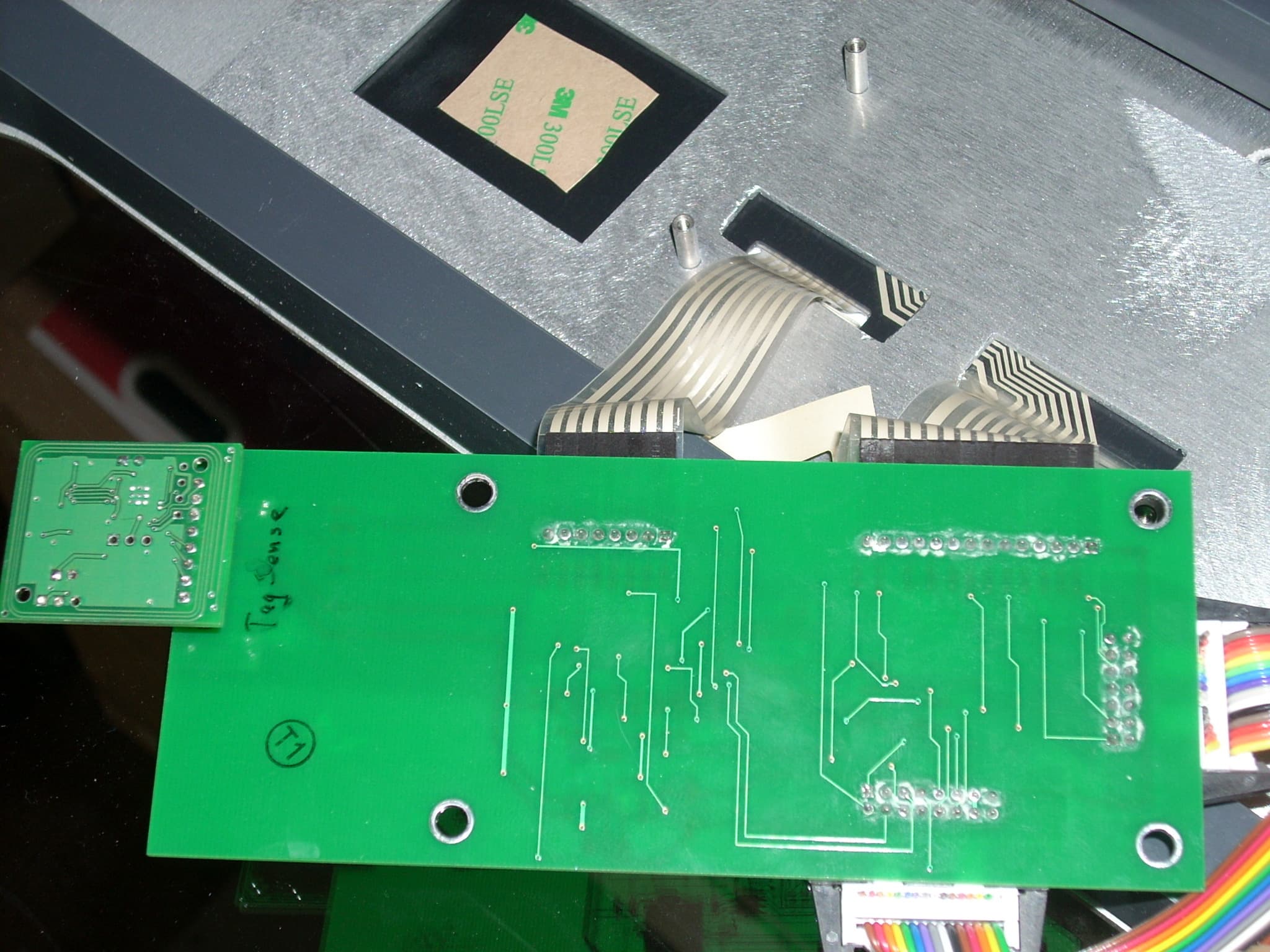
UQY-PROX1
Jan 12, 2010RFID Module
Equipment Class
DXX - Part 15 Low Power Communication Device Transmitter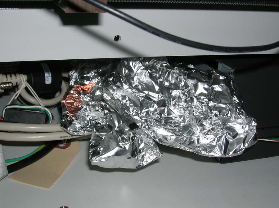
UQY-HF1000
Feb 15, 2007RFID Tag Reader
Equipment Class
DXX - Part 15 Low Power Communication Device Transmitter