URGR224012INDOOR EQUIPMENT LOCATION SYSTEM
RadarFind Corporation
Click to zoom
Application Details
- Equipment Class
- DXX - Part 15 Low Power Communication Device Transmitter
- Date of Grant
- Sep 22, 2010
- Application Purpose
- Original Equipment
- Date of Application
- Sep 16, 2010
- Equipment Note
- INDOOR EQUIPMENT LOCATION SYSTEM
- Frequency Range
- 905.00000000 - 918.00000000
- Company
- RadarFind Corporation
- Country
- United States
Documents & Files
Document Text
Text extracted from the exhibit documents filed with the FCC. Open a document above to read the original.
Users Manual
Copyright © RadarFind Corp 2008 V2 Reader Installation Instructions For Reader Models: R22-1012 with P10-xx10 PlugSert option R22-4012 with 80-113-1002 external power supply RadarFind™ Corporation 877-RadarFind (723-2734) www.radarfind.com Radarfind Corporation 8/25/2010 PLM Reader Installation Instructions Copyright © RadarFind Corp 2010 pg. 2 DANGER: • Risk of electric shock. Disconnect all supplies before working on any circuit. • It is important to follow all instructions shipped with this product. Failure to follow all safety precautions and instructions may result in property damage, serious injury, or death to you or others. Cautions: • Risk of malfunction. Use only copper wires of size 12AWG (or larger) suitable for 105°C (221°F). • Installation should conform to national, state, and local electrical codes. • Gauge of electric supply wires should be of appropriate section, function of line current, as per NEC electrical code. • This device must be installed directly into the electrical system. • This device must be installed by a trained and licensed electrician who is thoroughly familiar with the National Electrical Code and follows the NEC Guidelines as well as state and local codes. Reader Model R22-1012 Fcc ID: URGR221012 [15.19] This device complies with Part 15 of the FCC Rules. Operation is subject to the following two conditions: (1) this device may not cause harmful interference, and (2) this device must accept any interference received, including interference that may cause undesired operation. [15.21] Information to user: Changes or modifications not expressly approved by the RadarFind Corporation could void the user's authority to operate the equipment [15.105] NOTE: This equipment has been tested and found to comply with the limits for a Class A digital device, pursuant to Part 15 of the FCC Rules. These limits are designed to provide reasonable protection against harmful interference when the equipment is operated in a commercial environment. This equipment generates, uses, and can radiate radio frequency energy and, if not installed and used in accordance with the instruction manual, may cause harmful interference to radio communications. Operation of this equipment in a residential area is likely to cause harmful interference in which case the user will be required to correct the interference at his own expense. [15.247] This equipment operates under Section 15.247 of the Title 47 FCC Rules. [15.249] This equipment operates under Section 15.249 of the Title 47 FCC Rules. This product protected by one or more of the following U.S. Patents: 7372365, 7525432 & 7528716. Other patents pending Radarfind Corporation 8/25/2010 PLM Reader Installation Instructions Copyright © RadarFind Corp 2010 pg. 3 General Safety Information • Wear safety goggles when working under conditions that might be hazardous to your eyes. • Keep tools where you and others will not fall over them. • Keep the installation area clear during the installation. • Do not wear loose clothing that could become caught in the equipment. Electrical Safety Information • Before working on electrical equipment, remove jewelry (necklaces, rings, watches, etc). • Locate the emergency on/off switch closest to the installation site. • Before installation, turn OFF the power. • Refer to the site’s safety precautions for details about site-specific hazards. • Refer to the Reader name plate for information on voltage and current. Contents General Installation Instructions ..................................................................................................................... 4 IMPORTANT INFORMATION .................................................................................................................... 4 Preparing for Installation ................................................................................................................................ 5 1 - Installing a RadarFind Plug-in Reader ...................................................................................................... 6 2 - Reversing the PlugSert in a Reader ........................................................................................................... 8 3 - Installing a RadarFind EVN Reader (with external power supply) ......................................................... 11 4 - Hard wiring a Reader .............................................................................................................................. 13 4.1 Removing the PlugSert ........................................................................................................................... 13 4.2 - Hard wired Reader Installation Procedure ........................................................................................... 14 5 - Reader Mounting Accessories ................................................................................................................ 16 Appendix A – Reader Indicator LED ........................................................................................................... 18 Appendix B – Technical Specifications ....................................................................................................... 19 Radarfind Corporation 8/25/2010 PLM Reader Installation Instructions Copyright © RadarFind Corp 2010 pg. 4 General Installation Instructions a- A RadarFind Reader as shipped can only be installed on receptacles with the ground pin up. If it is necessary to install a Reader 180 degrees off-axis from the existing receptacle the orientation of the Reader PlugSert may be reversed (See Section 2) b- If a Reader requires being installed at 90 degrees to the existing receptacle, must be offset, installed over a double gang plate, or installed over a GFCI or single outlet receptacle the services of an electrician is required. (See Section 4) c- In some locations where the only available power is on a plug-strip, head-board unit, or behind a metal cabinet or re…
Text truncated - open the document above for the full version.
Cover Letter(s)
September 15th, 2 010 Federal Communications Commission Office of Engineering Technology Equipment Authorization Division 7435 Oakland Mills Road Columbia, MD 21046 Subject: Permanent Confidentiality Request for FCC IDs: URGT21122, URGT11122, URGT42140, URGT33110, URGR221012, and URGR224012 Dear Sir or Madam: RadarFind Corporation respectfully requests that the following exhibits accompanying this application be made permanently confidential and withheld from public disclosure: • Theory of Operation / Technical Description • Circuit Schematics • Bill of Materials / Parts List • Block Diagram • Tune-Up Procedure RadarFind Corporation al so requests that the following documents accompanying this application be made temporarily confi denti al for 180 days: • Installation or user operation manuals • Internal photographs RadarFind also understands that the following exhibits are not confidential: • Form 731 • External product photographs, label location photographs or label “artwork” drawings • EMC test lab reports or test lab setup photographs Sincerely, Stephen C. Snell, Hardware Manager RadarFind Corporation SCS / g w r RadarFind Corporation 2100 Gateway Centre Blvd. Suite 150 Morrisville, NC 27560-6230 (919) 228-2100 office (919) 287-2483 fax www.radarfind.com
External Photos
RadarFind Corporation Page 1 of 2 FCC Exhibit F C C I D : U RGR224012 Product: (DC Input) Re a d e r Model R22-4012 Date: 2010/08/19 R e v i s i o n : 1 External Device Photographs RadarFind Corporation Page 2 of 2
ID Label/Location Info
RadarFind Corporation P a g e 1 o f 2 FCC Exhibit FCC ID: U RGR2 24012 Product: “Reader” m od e l R22-4012 Date: 2010/08/29 R e v i s i o n : 1 FCC ID Label Artwork The following page is the drawing detailing the FCC ID label for this product.
ID Label/Location Info
RadarFind Corporation P a g e 1 o f 1 FCC Exhibit FCC ID: U RGR2 24012 Product: “Reader” m od e l R22-4012 Date: 2010/08/26 R e v i s i o n : 1 FCC ID Label Location Photograph
Internal Photos
RadarFind Corporation Page 1 of 4 FCC Exhibit F C C I D : U RGR2 24012 Product: Reader Model R22-4012 Date: 2010/08/19 R e v i s i o n : 1 Internal Device Photographs RadarFind Corporation Page 2 of 4 RadarFind Corporation Page 3 of 4 RadarFind Corporation Page 4 of 4
Test Report
Underwriters Laboratories Inc. 12 Laboratory Dr. Research Triangle Park, NC 27709 www.ul.com/emc (919) 549-1400 Lab Number: 10LB048 Project Number: 10RT02887 File Number: MC15465 Date: July 22, 2010 Models: Reader Models R22-4012 (DC) (FCC ID: URGR224012) Electromagnetic Compatibility Test Report For RadarFind Corp. Raleigh, NC Copyright 2010 Underwriters Laboratories Inc. Underwriters Laboratories Inc. authorizes the above-named company to reproduce this Report provided it is reproduced in its entirety. Underwriters Laboratories Inc. A not-for-profit organization dedicated to public safety and committed to quality service for over 100 years 12 Laboratory Dr. Research Triangle Park, NC 27709 Tel: (919) 549-1400 Project Number: 10RT02887 File Number: MC15465 Page 2 of 30 Model Number: Reader Model R22-4012 Client Name: RadarFind Corp. FCC ID: URGR224012 Test Report Details Tests Performed By: Underwriters Laboratories Inc. 12 Laboratory Dr. Research Triangle Park, NC 27709 Tests Performed For: RadarFind Corporation A TeleTracking Technologies Company 2100 Gateway Centre Blvd., Suite 150 Morrisville, NC 27560 Applicant Contact: Mr. Steve Snell Title: Director, Hardware Engineering Phone: (919) 228-2170 E-mail: [email protected] Test Report Date: July 15, 2010 Product Type: Low-Powered Transmitter Product standards FCC Part 15, Subpart C, 15.249 Model Number: Reader Models R22-4012 (DC) Sample Serial Number: Unserialized production samples EUT Category: Frequency Hopping Spread Spectrum Transmitter Testing Start Date: July 6, 2010 Date Testing Complete: July 12, 2010 Overall Results: Compliant Underwriters Laboratories Inc. reports apply only to the specific samples tested under stated test conditions. All samples tested were in good operating condition throughout the entire test program. It is the manufacturer's responsibility to assure that additional production units of this model are manufactured with identical electrical and mechanical components. Underwriters Laboratories Inc. shall have no liability for any deductions, inferences or generalizations drawn by the client or others from Underwriters Laboratories Inc. issued reports. This report shall not be used to claim, constitute or imply product certification, approval, or endorsement by NVLAP, NIST, A2LA, or any agency of the US government. This report may contain test results that are not covered by the NVLAP or A2LA accreditation. The scope of accreditation is limited to the specific tests that are listed on the NVLAP and/or A2LA websites referenced at the end of this report. Underwriters Laboratories Inc. 12 Laboratory Dr. Research Triangle Park, NC 27709 USA Tel.: 919 549-1400 Rev. No 1.0 EMC Report 2010-87-EM-F0042 Project Number: 10RT02887 File Number: MC15465 Page 3 of 30 Model Number: Reader Model R22-4012 Client Name: RadarFind Corp. FCC ID: URGR224012 Report Directory 1.0 G E N E R A L - Product Description................................................................................................................4 1.1 Equipment Description.................................................................................................................................4 1.2 Equipment Marking Plate.............................................................................................................................4 1.3 Device Configuration During Test................................................................................................................5 1.3.1 Equipment Used During Test:..................................................................................................................5 1.3.2 Input/Output Ports:...................................................................................................................................5 1.3.3 EUT Internal Operating Frequencies:......................................................................................................6 1.3.4 Power Interface:.......................................................................................................................................6 1.4 Block Diagram:.............................................................................................................................................7 1.5 Description of X and Y Axis Product Orientations........................................................................................7 1.6 EUT Configurations......................................................................................................................................7 1.7 EUT Operation Modes..................................................................................................................................8 2.0 Summary..........................................................................................................................................................9 2.1 Deviations from standard test methods........................................................................................................9 2.2 Device Modifications Necessary for Compliance.........................................................................................9 2.3 Reference Standards...................................................................................................................................9 2.4 Results Summary.........................................................................................................................................9 2.5 Test Scope...................................................................................................................................................9 3.0 Calibration of Equipment Used for Measurement..........................................................................................10 4.0 EMISSIONS TEST RESULTS........................................................................................................................10 4.1 Test Conditions and Results – RADIATED POWER…
Text truncated - open the document above for the full version.
Test Setup Photos
Job Number: 10RT02887 File Number: MC15465 Page 1 of 2 Model Number: Reader Model R22-4012 (DC) Client Name: Radarfind Corp. FCC ID: URGR224012 1.1.1 Radiated Spurious Emissions – Reader – DC Powered Figure 1 Test setup photo for Radiated Emissions (Reader, X and Y Orientations) Job Number: 10RT02887 File Number: MC15465 Page 2 of 2 Model Number: Reader Model R22-4012 (DC) Client Name: Radarfind Corp. FCC ID: URGR224012 Figure 2 Test Setup for Conducted Emissions – DC Reader
Contact Information
Applicant
Stephen Snell(Manager)
Test Firm
UL LLCRick Titus
Technical Specifications
| # | Rule Parts | Frequency Range | Power Output |
|---|---|---|---|
| 1 | 15C | 905 MHz - 918 MHz | - |
Other Applications from RadarFind Corporation
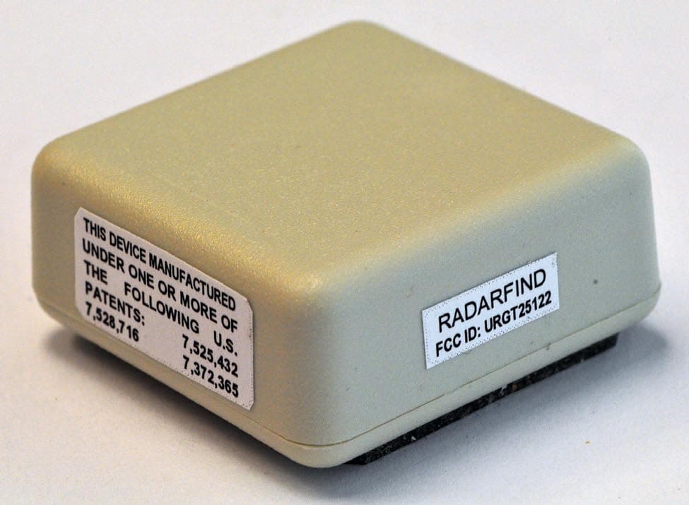
URGT25122
Jul 26, 2011Indoor Equipment Location System
Equipment Class
DXX - Part 15 Low Power Communication Device Transmitter
URGT11122
Sep 22, 2010INDOOR EQUIPMENT LOCATION SYSTEM
Equipment Class
DXX - Part 15 Low Power Communication Device Transmitter
URGT33110
Sep 22, 2010INDOOR EQUIPMENT LOCATION SYSTEM
Equipment Class
DXX - Part 15 Low Power Communication Device Transmitter
URGT21122
Sep 22, 2010INDOOR EQUIPMENT LOCATION SYSTEM
Equipment Class
DXX - Part 15 Low Power Communication Device Transmitter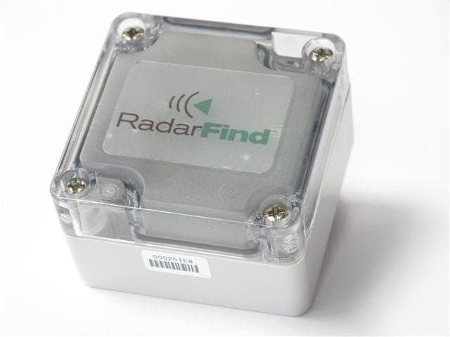
URGT42140
Sep 22, 2010INDOOR EQUIPMENT LOCATION SYSTEM
Equipment Class
DXX - Part 15 Low Power Communication Device Transmitter