URGT42140INDOOR EQUIPMENT LOCATION SYSTEM
RadarFind Corporation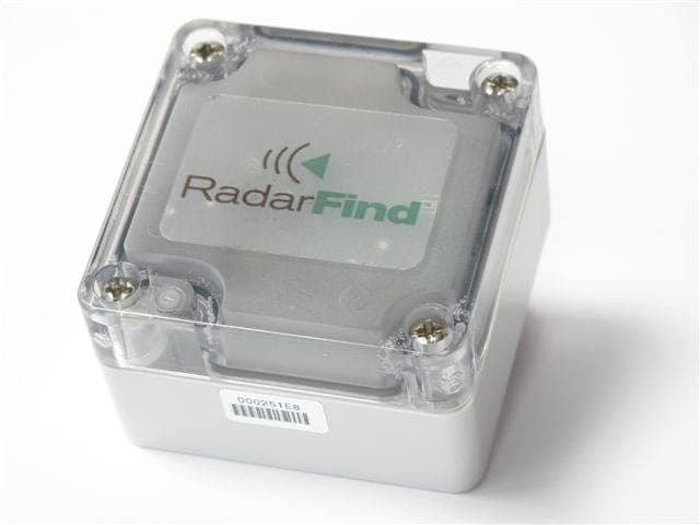
Click to zoom
Application Details
- Equipment Class
- DXX - Part 15 Low Power Communication Device Transmitter
- Date of Grant
- Sep 22, 2010
- Application Purpose
- Original Equipment
- Date of Application
- Sep 16, 2010
- Equipment Note
- INDOOR EQUIPMENT LOCATION SYSTEM
- Frequency Range
- 905.00000000 - 926.90000000
- Company
- RadarFind Corporation
- Country
- United States
Documents & Files
Document Text
Text extracted from the exhibit documents filed with the FCC. Open a document above to read the original.
Users Manual
Copyright © RadarFind Corp 2008 S‐Tag Model ‐ T42‐140 Temperature Monitoring Tag Installation Instructions RadarFind™ Corporation 877‐RadarFind (723‐2734) www.radarfind.com Radarfind Corporation 8/25/2010 A-Tag Installation Instructions Page 2 Copyright © RadarFind Corp 2009 Warnings: It is important to follow all instructions shipped with this product. UNPACKING: After unpacking the unit, examine it for damage that may have occurred in transit. If the equipment has been damaged, do not attempt to install or operate it. File a claim immediately with the carrier stating the extent of the damage, or contact RadarFind customer service for repair or replacement. Read and understand all instructions before installing or operating this equipment. The selection of the mounting location for the device is to be accomplished under the direction of the director of Clinical Engineering and conform to all company policies, and must be in accordance with specifications in the sub‐chapter for each device type. CAUTION: Risk of malfunction. Install these devices only in areas with an ambient temperature between 0° and 50°C. [15.19] This device complies with Part 15 of the FCC Rules. Operation is subject to the following two conditions: (1) this device may not cause harmful interference, and (2) this device must accept any interference received, including interference that may cause undesired operation. [15.21] Information to user: Changes or modifications not expressly approved by the RadarFind Corporation could void the user's authority to operate the equipment [15.105] NOTE: This equipment has been tested and found to comply with the limits for a Class A digital device, pursuant to Part 15 of the FCC Rules. These limits are designed to provide reasonable protection against harmful interference when the equipment is operated in a commercial environment. This equipment generates, uses, and can radiate radio frequency energy and, if not installed and used in accordance with the instruction manual, may cause harmful interference to radio communications. Operation of this equipment in a residential area is likely to cause harmful interference in which case the user will be required to correct the interference at his own expense. [15.249] This equipment operates under Section 15.249 of the Title 47 FCC Rules. This product protected by one or more of the following U.S. Patents: 7372365, 7525432 & 7528716. Other patents pending. Radarfind Corporation 8/25/2010 A-Tag Installation Instructions Page 3 Copyright © RadarFind Corp 2009 Contents of standard package: (1) T42‐140 Temperature Monitoring Tag Radarfind Corporation 8/25/2010 A-Tag Installation Instructions Page 4 Copyright © RadarFind Corp 2009 Accessories Adhesive Pad for permanent mounting ‐ # 90‐300‐303 Radarfind Corporation 8/25/2010 A-Tag Installation Instructions Page 5 Copyright © RadarFind Corp 2009 General Guidelines: Temperature monitoring tags have a maximum range of ‐40C to +70c Example Status tag placement Select a standard location in each monitored unit where the tag is not obstructed by metal containers or liquids which may interfere with the tags reporting signals. Placing the tag in the door shelf is a good option if available. Using adhesive pads – There are adhesive pads available to attach the tags to the sides of the refrigerator if desires. Radarfind Corporation 8/25/2010 A-Tag Installation Instructions Page 6 Copyright © RadarFind Corp 2009 Assigning a Temperature Tag to a device: 1 – NAME ‐ Create or select the correct device. 2 – DESCRIPTION ‐Give the device a Name and Description. 3 – LOCATION ‐Select the correct LocationID for where the device is located. This will display the device in the correct place on the maps. (Refer to a copy of the RadarFind installation maps to select the LocationID) 4 –TAG ‐Enter the TagID of the Temperature Monitiring Tag placed in that device. 5 – ACTIVE DEVICE ‐ Select whether the device is Active or not. Devices which are not Active will not appear in the default user interfaces or generate alerts. (For example mark a device as InActive when the unit is out of service ) 6 – MIN & MAX ‐ Set the acceptable temperature range for the device. If the device goes out of the range specified an alert may be sent. Some adjustment of this range may be required depending on the normal fluctuations of the device over time. Set the range to accept normal fluctuations, but to warn if those normal conditions are not maintained. Radarfind Corporation 8/25/2010 A-Tag Installation Instructions Page 7 Copyright © RadarFind Corp 2009 7 – TRACK EVERY ‐ Set the time periodicity to log the temperature tracking record. This is the periodicity at which the temperature for this device is recorded when the temperature is within the normal range. When the temperature deviates from the normal range as set the temperature will be logged every 5 minutes. 8 – ACTIVATE ALERT‐ Select whether the Alert function for this device is Active or not. Alerts which are not Active will generate alerts. (For example mark an Alert as InActive when the unit is out of service ) 9 – SEND TO – Enter the email address(s) for persons who should receive email notifications when this Alert is triggered. 10 – SEND WHEN – Enter the time the device has to remain out of temperature range before sending an email Alert,. 11 – SAVE the configuration. (Location with Alert and Selected Alerts refer to a visible and audible Ethernet attached alerting device, for future use) 8/25/ 2 2010 DC power: Power consu m Communication Transmit Power Antenna: Communicati o Operating: Packaging: Accessories: Dimensions: Model mption: ns r ons: R Radarf A-Tag Ins Copyright © Techn T42‐140 ‐ T Internal sealed l Average 15uA 902‐928 MHz FS K +10dBm maxim Unity gain isotro FCC Subpart 15. ‐40 to +70º C, 5 % ABS and Polycar Adhesive pad Tag T42‐140 (2 RadarFind find Corporati stallation Instr © RadarFind Co ical Specificat i Temperatur ithium battery K mum ‐ *nominal* T opic 24…
Text truncated - open the document above for the full version.
Cover Letter(s)
September 15th, 2 010 Federal Communications Commission Office of Engineering Technology Equipment Authorization Division 7435 Oakland Mills Road Columbia, MD 21046 Subject: Permanent Confidentiality Request for FCC IDs: URGT21122, URGT11122, URGT42140, URGT33110, URGR221012, and URGR224012 Dear Sir or Madam: RadarFind Corporation respectfully requests that the following exhibits accompanying this application be made permanently confidential and withheld from public disclosure: • Theory of Operation / Technical Description • Circuit Schematics • Bill of Materials / Parts List • Block Diagram • Tune-Up Procedure RadarFind Corporation al so requests that the following documents accompanying this application be made temporarily confi denti al for 180 days: • Installation or user operation manuals • Internal photographs RadarFind also understands that the following exhibits are not confidential: • Form 731 • External product photographs, label location photographs or label “artwork” drawings • EMC test lab reports or test lab setup photographs Sincerely, Stephen C. Snell, Hardware Manager RadarFind Corporation SCS / g w r RadarFind Corporation 2100 Gateway Centre Blvd. Suite 150 Morrisville, NC 27560-6230 (919) 228-2100 office (919) 287-2483 fax www.radarfind.com
External Photos
RadarFind Corporation Page 1 of 1 FCC Exhibit F C C I D : U RGT42140 Product: T a g Mod e l T42-140 Date: 2010/08/19 R e v i s i o n : 1 External Device Photographs
ID Label/Location Info
RadarFind Corporation P a g e 1 o f 2 FCC Exhibit FCC ID: URGT42140 Product: Tag model T42-140 Date: 2/9/2010 Revision: 1 FCC ID Label Artwork The following page is the drawing detailing the FCC ID label for this product.
ID Label/Location Info
RadarFind Corporation P a g e 1 o f 1 FCC Exhibit FCC ID: URGT42140 Product: Tag Model T42-140 Date: 2010/08/26 R e v i s i o n : 1 FCC ID Label Location Photograph
Internal Photos
RadarFind Corporation Page 1 of 2 FCC Exhibit F C C I D : U RGT42140 Product: Tag Model T42-140 Date: 2010/08/19 R e v i s i o n : 1 Internal Device Photographs RadarFind Corporation Page 2 of 2
Test Report
Underwriters Laboratories Inc. 12 Laboratory Dr. Research Triangle Park, NC 27709 www.ul.com/emc (919) 549-1400 Lab Number: 10LB048 Project Number: 10RT02887 File Number: MC15465 Date: July 22, 2010 Models: Tag Models T42-140 (FCC ID: URGT42140) Electromagnetic Compatibility Test Report For RadarFind Corp. Raleigh, NC Copyright 2010 Underwriters Laboratories Inc. Underwriters Laboratories Inc. authorizes the above-named company to reproduce this Report provided it is reproduced in its entirety. Underwriters Laboratories Inc. A not-for-profit organization dedicated to public safety and committed to quality service for over 100 years 12 Laboratory Dr. Research Triangle Park, NC 27709 Tel: (919) 549-1400 Project Number: 10RT02887 File Number: MC15465 Page 2 of 24 Model Number: Tag Model T42-140 Client Name: RadarFind Corp. FCC ID: URGT42140 Test Report Details Tests Performed By: Underwriters Laboratories Inc. 12 Laboratory Dr. Research Triangle Park, NC 27709 Tests Performed For: RadarFind Corporation A TeleTracking Technologies Company 2100 Gateway Centre Blvd., Suite 150 Morrisville, NC 27560 Applicant Contact: Mr. Steve Snell Title: Director, Hardware Engineering Phone: (919) 228-2170 E-mail: [email protected] Test Report Date: July 15, 2010 Product Type: Low-Powered Transmitter Product standards FCC Part 15, Subpart C, 15.249 Model Number: Tag Model T42-140 Sample Serial Number: Unserialized production samples EUT Category: Frequency Hopping Spread Spectrum Transmitter Testing Start Date: July 6, 2010 Date Testing Complete: July 12, 2010 Overall Results: Compliant Underwriters Laboratories Inc. reports apply only to the specific samples tested under stated test conditions. All samples tested were in good operating condition throughout the entire test program. It is the manufacturer's responsibility to assure that additional production units of this model are manufactured with identical electrical and mechanical components. Underwriters Laboratories Inc. shall have no liability for any deductions, inferences or generalizations drawn by the client or others from Underwriters Laboratories Inc. issued reports. This report shall not be used to claim, constitute or imply product certification, approval, or endorsement by NVLAP, NIST, A2LA, or any agency of the US government. This report may contain test results that are not covered by the NVLAP or A2LA accreditation. The scope of accreditation is limited to the specific tests that are listed on the NVLAP and/or A2LA websites referenced at the end of this report. Underwriters Laboratories Inc. 12 Laboratory Dr. Research Triangle Park, NC 27709 USA Tel.: 919 549-1400 Rev. No 1.0 EMC Report 2010-87-EM-F0042 Project Number: 10RT02887 File Number: MC15465 Page 3 of 24 Model Number: Tag Model T42-140 Client Name: RadarFind Corp. FCC ID: URGT42140 Report Directory 1.0 G E N E R A L - Product Description................................................................................................................4 1.1 Equipment Description.................................................................................................................................4 1.2 Equipment Marking Plate.............................................................................................................................4 1.3 Device Configuration During Test................................................................................................................5 1.3.1 Equipment Used During Test:..................................................................................................................5 1.3.2 Input/Output Ports:...................................................................................................................................5 1.3.3 EUT Internal Operating Frequencies:......................................................................................................6 1.3.4 Power Interface:.......................................................................................................................................6 1.4 Block Diagram:.............................................................................................................................................7 1.5 Description of X and Y Axis Product Orientations........................................................................................7 1.6 EUT Configurations......................................................................................................................................7 1.7 EUT Operation Modes..................................................................................................................................8 2.0 Summary..........................................................................................................................................................9 2.1 Deviations from standard test methods........................................................................................................9 2.2 Device Modifications Necessary for Compliance.........................................................................................9 2.3 Reference Standards...................................................................................................................................9 2.4 Results Summary.........................................................................................................................................9 2.5 Test Scope...................................................................................................................................................9 3.0 Calibration of Equipment Used for Measurement..........................................................................................10 4.0 EMISSIONS TEST RESULTS........................................................................................................................10 4.1 Test Conditions and Results – RADIATED POWER / RADIATED SPURIOUS EMISSIONS…
Text truncated - open the document above for the full version.
Test Setup Photos
Job Number: 10RT02887 File Number: MC15465 Page 1 of 1 Model Number: Model T42-140 Client Name: Radarfind Corp. FCC ID: URGT42140 1.1.1 Radiated Spurious Emissions – Tag #1 (Model T42-140) Figure 1 Test setup photo for Radiated Emissions (Tag #1, X-Y Orientation)
Contact Information
Applicant
Stephen Snell(Manager)
Test Firm
UL LLCRick Titus
Technical Specifications
| # | Rule Parts | Frequency Range | Power Output |
|---|---|---|---|
| 1 | 15C | 905 MHz - 926.9 MHz | - |
Other Applications from RadarFind Corporation
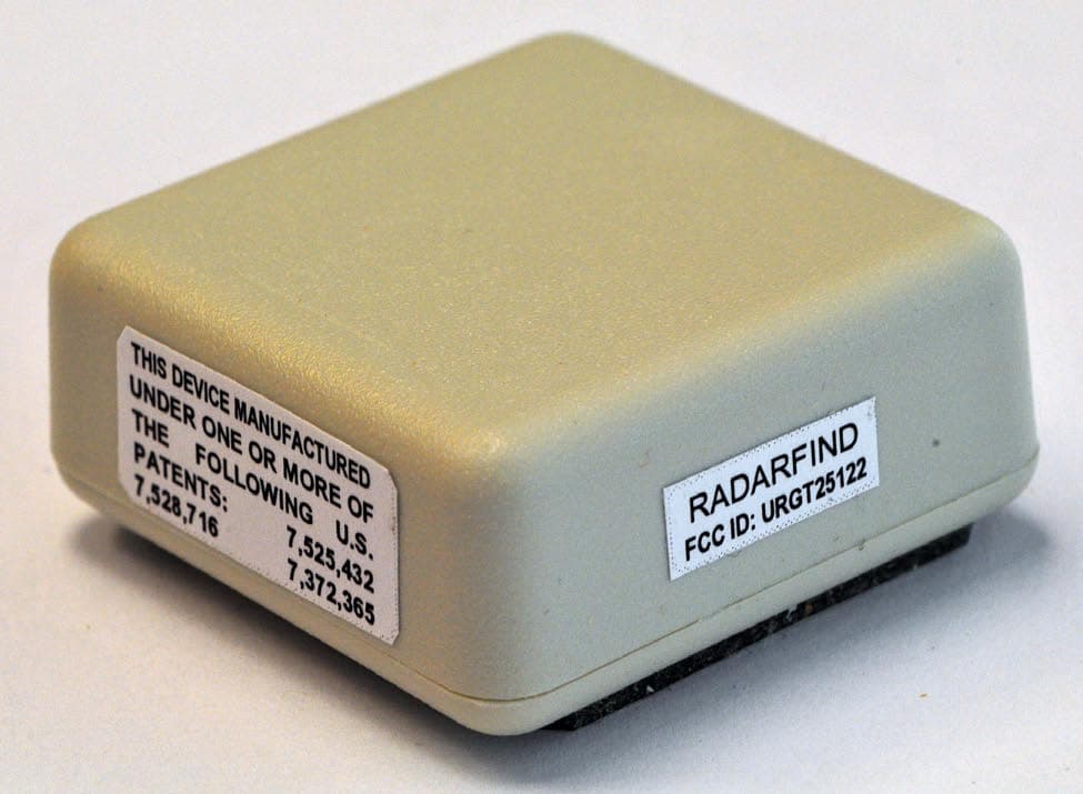
URGT25122
Jul 26, 2011Indoor Equipment Location System
Equipment Class
DXX - Part 15 Low Power Communication Device Transmitter
URGT11122
Sep 22, 2010INDOOR EQUIPMENT LOCATION SYSTEM
Equipment Class
DXX - Part 15 Low Power Communication Device Transmitter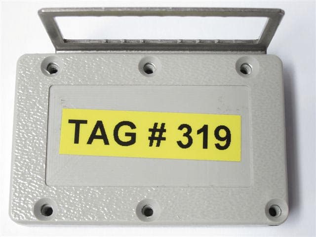
URGT33110
Sep 22, 2010INDOOR EQUIPMENT LOCATION SYSTEM
Equipment Class
DXX - Part 15 Low Power Communication Device Transmitter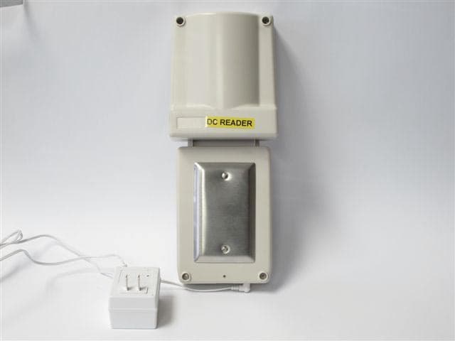
URGR224012
Sep 22, 2010INDOOR EQUIPMENT LOCATION SYSTEM
Equipment Class
DXX - Part 15 Low Power Communication Device Transmitter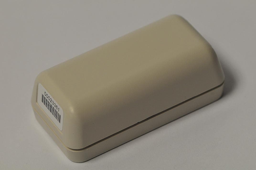
URGT21122
Sep 22, 2010INDOOR EQUIPMENT LOCATION SYSTEM
Equipment Class
DXX - Part 15 Low Power Communication Device Transmitter