URGT10B011RF Location Tag
RadarFind Corporation
Click to zoom
Application Details
- Equipment Class
- DXX - Part 15 Low Power Communication Device Transmitter
- Date of Grant
- Jan 04, 2007
- Application Purpose
- Original Equipment
- Date of Application
- Dec 27, 2006
- Equipment Note
- RF Location Tag
- Frequency Range
- 915.00000000 - 915.00000000
- Company
- RadarFind Corporation
- Country
- United States
Documents & Files
Document Text
Text extracted from the exhibit documents filed with the FCC. Open a document above to read the original.
Users Manual
12/28/2006 Radarfind Corporation— Phone 877 Radarfind—www.radarfind.com Installation Instructions Radarfind Corporation ™ A-Tag—Non-Status Model T10-B011 12/28/2006 Radarfind Corporation— Phone 877 Radarfind—www.radarfind.com 2 Warnings: It is important to follow all instructions shipped with this product. Failure to follow all safety precautions and instructions may result in property damage, serious in- jury, or death to you or others. UNPACKING: After unpacking the unit, examine it for damage that may have occurred in transit. If the equipment has been damaged, do not attempt to install or operate it. File a claim immediately with the carrier stating the extent of the damage, or contact RadarFind customer service for repair or replacement. Read and understand all instructions before installing or operating this equipment. The selection of the mounting location for the device is to be accomplished under the direction of the director of Clinical Engineering and conform to all company policies, and must be in accordance with specifications in the sub-chapter for each device type. CAUTION: Risk of malfunction. Install these devices only in areas with an ambient temperature between 0° and 50°C. [15.19] This device complies with Part 15 of the FCC Rules. Operation is subject to the following two conditions: (1) this device may not cause harmful interference, and (2) this device must accept any interference received, including interference that may cause undesired operation. [15.21] Information to user: Changes or modifications not expressly approved by the RadarFind Corporation could void the user's authority to operate the equipment [15.105] NOTE: This equipment has been tested and found to comply with the limits for a Class A digital device, pursuant to Part 15 of the FCC Rules. These limits are designed to provide reasonable protection against harmful interference when the equipment is operated in a commercial environ- ment. This equipment generates, uses, and can radiate radio frequency energy and, if not installed and used in accordance with the instruction manual, may cause harmful interference to radio com- munications. Operation of this equipment in a residential area is likely to cause harmful interference in which case the user will be required to correct the interference at his own expense. [15.249] This equipment operates under Section 15.249 of the Title 47 FCC Rules. 12/28/2006 Radarfind Corporation— Phone 877 Radarfind—www.radarfind.com 3 Contents of standard package: (1) - T10-B011 – A-Status Tag (1) TBA-3160 – Mounting Base (1) A12-1A0B – Adhesive Pad (2) A12-1T0B – Plastic mounting strap 12/28/2006 Radarfind Corporation— Phone 877 Radarfind—www.radarfind.com 4 Accessories A12-3T00 (2) Stainless steel mounting straps (for application of Radarfind tag mounting base (Part# TBA-3160) to tubular structures) Note: For best performance the steel straps require a special tool to tighten and cut the strap. 12/28/2006 Radarfind Corporation— Phone 877 Radarfind—www.radarfind.com 5 General Guidelines: Al l tags on an asset type should be the same type, e.g. all infusion pumps should have an A-Status Type tag. Select a standard location on each asset type for the tag. For A-Status tags select a location where the status indicator is plainly visible and can be easily accessed by the user when switching the status switch. The tag location should not interfere with normal use of the asset, and have sufficient clearance on the open end of the base to insert the locking base key and insert and remove the tag. For best performance do not place the tag in a location covered with metal, such as inside of a control box or enclosed area under a bed frame. Using adhesive pad – Clean the area on the asset with alcohol to ensure a good bond. Remove white side of the adhesive covering and place on tag base, aligning the hole in the center of the adhesive over the base locking mechanism. Remove red backing and apply to asset. (Be sure to leave sufficient clearance at the open end of the base to insert and remove the tag from the base) Adhesive Orientation Apply adhesive to base 1st Adhesive mounting tips for curved surfaces: If the target location is not completely flat you may need to add strips under the ends of the adhesive pad (cut the strips from a spare pad) Building up adhesive to conform to curves 12/28/2006 Radarfind Corporation— Phone 877 Radarfind—www.radarfind.com 6 Using the supplied plastic strap: Use the supplied plastic “Tie-Rap” to attach the tag base to permanently mounted cords or handles of assets where there is no convenient flat mounting spot. Use tie-rap to attach tag to oddly shaped assets Mounting to tubular fixtures: Use stainless steel straps to attach tag to tubes or poles. For best results mounting to tubular fixtures, such as IV poles or wheelchair frames, the locking base is equipped with strapping holes. These holes are designed to be used with thin stainless steel straps, available from Radarfind ( Part # A12-3T00 ) or Panduit: http://www.panduit.com/search/search_results.asp?Ne=1&recName=MLT1S%2DCP&N=5000001+336+3000858+®ion=USA Note: that the best results are obtained by using the strapping gun designed for these steel straps. 12/28/2006 Radarfind Corporation— Phone 877 Radarfind—www.radarfind.com 7 Installation Steps – Attaching tags with adhesive: Step # 1 - Select location for tag and clean area for adhesive with alcohol. Step # 2 - Attach adhesive to tag base with adhesive or straps. Step # 3 – (Assuming that you have already entered your assets ) Select asset by entering the serial number or asset inventory number. Enter or scan tag ID into the Radarfind software, select which tag type, status or non-status, and hit <Tag!> Once a tag is assigned to an asset any searching or display can be done by looking for the asset. If you need to remove a tag from an asset please un-assign the asset in the following screen by selecting the correct asset and clicking DETA…
Text truncated - open the document above for the full version.
Cover Letter(s)
RADARFIND CORPORATION January 4, 2007 Federal Communications Commission Office of Engineering Technology Equipment Authorization Division 7435 Oakland Mills Road Columbia, MD 21046 Subject: Permanent Confidentiality Request for FCC ID: URGT11B011 Dear Sir or Madam: RadarFind Corporation respectfully requests that the following documents accompanying this application: ? Block diagram and operational description ? Circuit schematics ? Bill of materials be made permanently confidential and withheld from public disclosure, in accordance with 47 CFR 0.457 and 47 CFR 0.459. These documents contain trade secrets, the public disclosure of which would put RadarFind at a competitive disadvantage. Photographs of the interior of the product are especially sensitive. The product is ultrasonically welded shut; no access to or view of the circuitry, or the proprietary board layout, is possible without destructive disassembly. Sincerely, Jl L;l; Chief Technology Officer
Test Report
Project: 06CA55823 File: MC15465 Report: 060112 Date: November 15, 2006 Model: T10-B011 and T11-A011 Test Report On Electromagnetic Compatibility Testing RadarFind Research Triangle Park, NC USA Copyright 2006 Underwriters Laboratories Inc. Underwriters Laboratories Inc. authorizes the above-named company to reproduce this Report provided it is reproduced in its entirety. Project: 06CA55823 Underwriters Laboratories, Inc. Issued: 11/15/06 File: MC15465 Test Report on Electromagnetic Compatibility Page 2 of 46 Test Report: 060112 Test Report Details: Tests Performed By: Underwriters Laboratories Inc. 12 Laboratory Drive Research Triangle Park, NC 27709 Tests Performed For: RadarFind 2 Davis Drive Research Triangle Park, NC 27709 USA Applicant Contact: Mr. Bobby Bahram (919) 765-0020 Test Report Number: 060112 Test Report Date: November 15, 2006 Product Type: Low-Powered Transmitter Model Number: T10-B011 and T11-A011 Sample Serial Number: Unserialized, pre-production sample Sample Tag Number: S06LB112 EUT Category: Transmitter - Low Powered EUT Type: Mounted to asset to be tracked Sample Receive Date: November 08, 2006 Testing Start Date: November 08, 2006 Date Testing Complete: November 08, 2006 Underwriters Laboratories Inc. reports apply only to the specific samples tested under stated test conditions. All samples tested were in good operating condition throughout the entire test program. It is the manufacturer's responsibility to assure that additional production units of this model are manufactured with identical electrical and mechanical components. Underwriters Laboratories Inc. shall have no liability for any deductions, inferences or generalizations drawn by the client or others from Underwriters Laboratories Inc. issued reports. This report shall not be used to claim, constitute or imply product certification, approval, or endorsement by NVLAP or any agency of the US government. This report may contain test results that are not covered by the NVLAP accreditation. The scope of accreditation is limited to the specific tests that are listed on the NVLAP certificates provided at the end of this report. Project: 06CA55823 Underwriters Laboratories, Inc. Issued: 11/15/06 File: MC15465 Test Report on Electromagnetic Compatibility Page 3 of 46 Test Report: 060112 Summary of Testing: Test Test Name Comply Does Not See # Test Requirement/Specification Comply Remark 1 Radiated Emissions - FCC Part 15.249 X - 47 CFR Part 15 Subpart C, Section 15.249 / RSS-210 Issue 6, Section A2.9 2 Radiated Disturbance Emissions - Occupied Bandwidth X - 47 CFR Part 15, Subpart C, RSS-210 Issue 6 3 Radiated Disturbance Emissions - Peak-to-Average Ratio X - 47 CFR Part 15, Subpart C, RSS-210 Issue 6 Remarks: 1) Modification Required to Comply: None. 2) Antenna - This transmitter contains an integrated antenna that cannot be removed by the user. 3) Measurement Site & Accreditations - All measurements were performed on Industry Canada registered site IC- 2953. All measurements were performed in accordance with NVLAP-accredited procedures. NVLAP scope of accreditation is included on Page 45 of this report. 4) RF Exposure - This device is exempt from routine evaluation to RF exposure requirements per FCC Part 2.1091. Output power is 143.6 nW EIRP (QP), therefore device is exempt from routine evaluation per Industry Canada RSS-102 Issue 2, Section 2.5.1. 5) Canada Emissions Designator – Emissions Designator is Q1D317K. 6) Transmitter Dimensions – Transmitter measures approx 1” x 1.5” at the longest/widest points. Due to the size and curvature of the plastic, the manufacturer could not legibly fit the FCC Part 15 statement on the device. The FCC ID number is placed on the transmitter and the FCC Part 15 statement is moved to the user manual. 7) Restricted Bands – Device transmit frequency is not located in a Restricted Band as defined in FCC Part 15.205. All spurious emissions, including those in Restricted Bands, comply with the field strength limits in FCC Part 15.209. Conclusion: The tests listed in the Summary of Testing section of this report have been performed and the results recorded by Underwriters Laboratories Inc. in accordance with the procedures stated in each test requirement and specification. The test list was determined by the Applicant as being applicable to the Equipment Under Test. As a result, the subject product has been verified to comply or not comply as noted in the Summary of Testing with each test specification. The test results relate only to the items tested. Prepared By: Reviewed By: Jim Marley Mark Nolting NARTE Certified EMC Engineer NARTE Accredited EMC Test Lab Engineer [email protected] [email protected] (919) 549-1408 (919) 549-1584 Project: 06CA55823 Underwriters Laboratories, Inc. Issued: 11/15/06 File: MC15465 Test Report on Electromagnetic Compatibility Page 4 of 46 Test Report: 060112 Test Facilities: Test Location A) 10-Meter Anechoic Chamber (Industry Canada - IC 2953, VCCI - R-722/C-2427) Constructed by Lindgren RF Enclosures, this room consists of a 17.9 by 12 by 8.3 m (inside clearance) shielded room lined with TDK absorber material. The walls, floor (conducting ground plane) and ceiling are constructed of double sided galvanized sheet steel supported by 19 mm thick particle board. The interior walls and ceiling are covered with 10 by 10 cm, 4.6 mm thick ferrite tiles and partially covered with polystyrene absorber cones. Removable floor tiles and cones covering the floor between the EUT and antenna are provided when RF immunity testing is performed. Room is provided with a 4.0 m diameter embedded turntable and a 1.2 by 2.1 m and 2.4 by 2.4 m double knife edge doors for access. Also, the room is fed electrical EUT power via permanently installed filters and is provided with a permanently mounted video surveillance camera. A remotely controllable antenna mast is located in the room for positioning the measuring antenna from 1 to 4 m above the ground plane.…
Text truncated - open the document above for the full version.
Test Setup Photos
Project: 06CA55823 Underwriters Laboratories, Inc. Issued: 11/15/06 File: MC15465 Test Setup Photos Page 1 of 3 Test Report: 060112 Worst Case EUT Arrangement (Upright): Radiated Emissions - FCC Part 15.249 Project: 06CA55823 Underwriters Laboratories, Inc. Issued: 11/15/06 File: MC15465 Test Setup Photos Page 2 of 3 Test Report: 060112 Worst Case Emissions - Test Set-Up Photo - Front: Radiated Emissions - FCC Part 15.249 Note: EUT is placed on top of a piece of foam approximately 3 inches high. This was used to reduce unwanted effects (reflections) from wood surface at high frequencies. It also aids in positioning the device. Project: 06CA55823 Underwriters Laboratories, Inc. Issued: 11/15/06 File: MC15465 Test Setup Photos Page 3 of 3 Test Report: 060112 Test 1, Item A – Worst Case Emissions - Test Set-Up Photo - Rear: Radiated Emissions - FCC Part 15.249
Contact Information
Applicant
Stephen Snell(Manager)
Technical Contact
ULjim marley
[email protected]9195491408
12 Laboratory Drive · Research Triangle Drive · United States
Test Firm
UL LLCRick Titus
Technical Specifications
| # | Rule Parts | Frequency Range | Power Output |
|---|---|---|---|
| 1 | 15C | 915 MHz - 915 MHz | - |
Other Applications from RadarFind Corporation
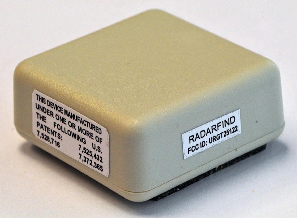
URGT25122
Jul 26, 2011Indoor Equipment Location System
Equipment Class
DXX - Part 15 Low Power Communication Device Transmitter
URGT11122
Sep 22, 2010INDOOR EQUIPMENT LOCATION SYSTEM
Equipment Class
DXX - Part 15 Low Power Communication Device Transmitter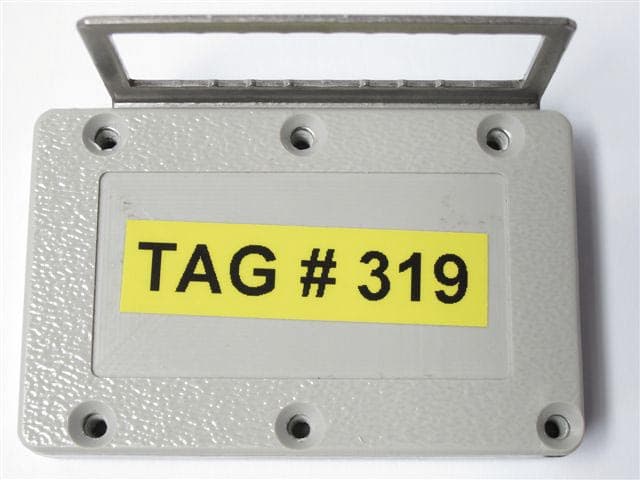
URGT33110
Sep 22, 2010INDOOR EQUIPMENT LOCATION SYSTEM
Equipment Class
DXX - Part 15 Low Power Communication Device Transmitter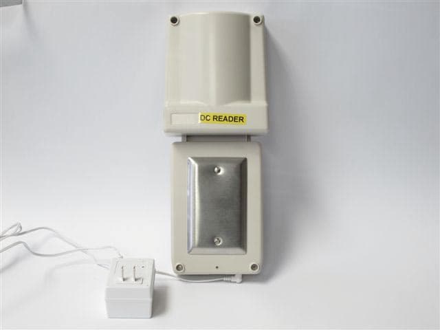
URGR224012
Sep 22, 2010INDOOR EQUIPMENT LOCATION SYSTEM
Equipment Class
DXX - Part 15 Low Power Communication Device Transmitter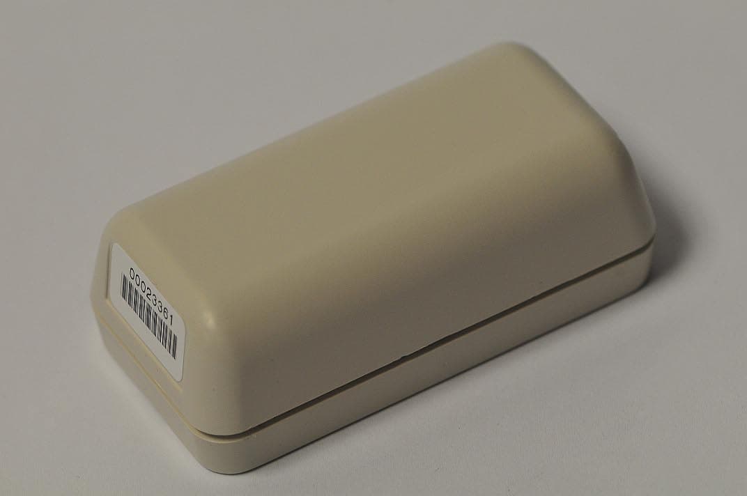
URGT21122
Sep 22, 2010INDOOR EQUIPMENT LOCATION SYSTEM
Equipment Class
DXX - Part 15 Low Power Communication Device Transmitter