USH00001Low Power Sensor
Carttronics LLC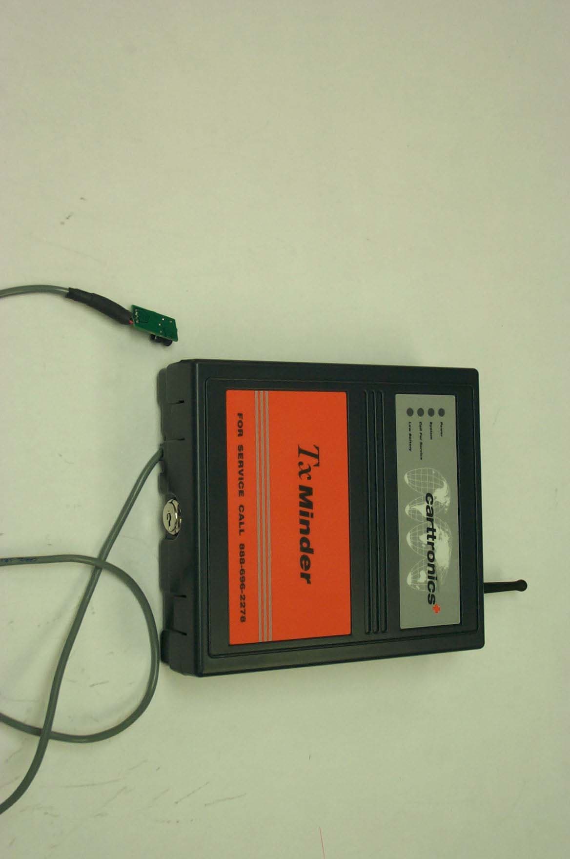
Click to zoom
Application Details
- Equipment Class
- DXX - Part 15 Low Power Communication Device Transmitter
- Date of Grant
- May 31, 2007
- Application Purpose
- Original Equipment
- Date of Application
- May 31, 2007
- Equipment Note
- Low Power Sensor
- Frequency Range
- 2405.00000000 - 2480.00000000
- Company
- Carttronics LLC
- Country
- United States
Documents & Files
Document Text
Text extracted from the exhibit documents filed with the FCC. Open a document above to read the original.
Users Manual
MX01 USER MANUAL Table of Contents Product Description............................................................................................................ 1 Settings................................................................................................................................1 Join A Network ................................................................................................................... 2 PRODUCT DESCRIPTION The MX01 is a low power sensor for use in retail monitoring applications. MX01 leverages the industry standard wireless IEEE 802.15.4 to seamlessly integrate with other retail solutions. By using industry standards and a modular sensor scheme, MX01 enables a wide range of sensing applications and network capabilities. With MX01, real time knowledge of the retail environment becomes possible. DIP Switch, SW4 Reset, Join, SW B Buttons Figure 1a: MX01 Assembly. Figure 1b: Assembled MX01 Board. S ETTINGS Properly assembled, the MX01 will monitor the ground loop antenna; connect to the modem or Ethernet board, battery or wall power supply, and the radio which can be seen in figure 1a and figure 1b. The locations of the DIP switches and the RESET, JOIN, and SW B buttons are also shown in figure 1b. Select the appropriate DIP settings for desired functionality using the following table: DIP Switch Operation 1 Neighbor 2 not used (off) 3 Test switch (must be off) 4 not used (off) 5 not used (off) Table 1: DIP Switch Options Table. Figure 2: SW 4 switch (Switch 3 is shown in the ON position). NOTE: All DIP switches MUST BE OFF for proper functionality. JOIN A NETWORK The following procedures outline how to join the MX01 radio board to a system network. Figure 3: Reset, Join, and SW B buttons. NOTE: Figure 4 is a rotated image of the GPRF board shown in figures 1a and 1b. Make sure to press the correct buttons when joining the system network. Join Operation Step 1: Find the nearest Network Router or the Network Integrator within radio range of the network device, typically between 60’ (20m) to 300’ (150m) depending upon the number and type of obstructions. Open the case and press and hold the Join button for at least 2 seconds. The blue network LED will light (on but not blink.) This indicates this device will accept new network members for 20 minutes. Step 2: Go back to the network device and press the join button once briefly. The blue LED will go on for 2 minutes or until the network device joins the local network. If the blue LED goes out and does not blink, the join was not a success and there is a problem. MT Restore Bypass Step 1: Hold down the SW B button for two seconds then press the reset button and wait for the green LED to flash. Once the green LED has flashed proceed with the standard Join operation described above. NOTE: There can be one and only one network integrator (SW4- Switch 3 ON). NOTE: If the network device powers up with the blue LED blinking, the NV Restore Bypass procedure must be followed to properly join the network. Antenna Information This device has been designed to operate with the antennas listed below, and having a maximum gain of 1.5 dB. Antennas not included in this list or having a gain greater than 1.5dB are strictly prohibited for use with this device. The required antenna impedance is 50ohms. Approved Antennas: Vendor: Centurion, Lincoln, NE. Vendor P/N: wcp2400-mmcx. FCC ID: USH00001 IC ID: 6834A-00001 WARNING The antenna used for this transmitter must be installed to provide a separation distance of at least 20 cm from all persons and must not be co-located or operating in conjunction with any other antenna or transmitter in its final installation. The installers must be provided with antenna installation instructions and transmitter operating conditions for satisfying RF exposure compliance. WARNING Any changes or modifications made to the MX01 not aforementioned in the User Manual, or expressly approved by the MX01 manufacturer, will void the user’s authority to operate the equipment. WARNING This equipment has been tested and found to comply with the limits for a Class B digital device, pursuant to Part 15 of the FCC Rules. These limits are designed to provide reasonable protection against harmful interference in a residential installation. This equipment generates, uses, and can radiate radio frequency energy and, if not installed and used in accordance with the instructions, may cause harmful interference to radio communications. However, there is no guarantee that interference will not occur in a particular installation. If this equipment does cause harmful interference to radio or television reception, which can be determined by turning the equipment off and on, the user is encouraged to try to correct the interference by one or more of the following measures: -Reorient or relocate the receiving antenna. -Increase the separation between the equipment and receiver -Connect the equipment into an outlet on a circuit different from that to which the receiver is connected. -Consult the dealer or an experienced radio/TV technician for help
Block Diagram
EXPERTISE ENGINEERING 4186 Sorrento Valley Blvd Suite J San Diego CA 92121 858 642-7639 ww.exp-eng.com TITLE: Size Rev. Document Number Drawn by: Date: A BLOCK DIAGRAM: TXMinder – 2.4GHz Transceiver Dante Galli 2/;18/2007 A Atmel ATMega128 Voltage Regulator Control Logic Digital / Analog Test Interface RX / LNA TX / RX Control Switch TX / PA Balun SPI 2.4 GHz 2.4 GHz ½ Wave Dipole 27 MHz CC2420 802.15.4 2.4 GHz Transciever Switching Regulator 3.3VDC Vin 4.5 – 18 VDC +3.3 VDC Sensor Detect Sensor Sensor IN RS232 MAX3221 UART Comm PortTo Modem/ LAN UART1 UART0 Test port to PC To LAN MODEM
Cover Letter(s)
February 15th, 2007 Equipment Authorization Division Federal Communications Commission 7435 Oakland Mills Road Columbia, MD 21046 FCC ID: USH00001 Product Name: MX01 – TX Minder Request for Confidentiality Pursuant to Sections 0.457 and 0.459 of the commission’s rules, we hereby request that the following documents be held confidential: • 50302-001 BOM • 50302-001 Schematic • Operational Description MX01 These materials contain trade secrets and proprietary information and are not customarily released to the public. The public disclosure of this information might be harmful to the company and provide unjustified benefits to our competitors. Dated this 15 Day of February 20 07 By: Luke Seed Signature Printed Title: Mechanical Engineer On behalf of : Carttronics Telephone: 760-707-1270
External Photos
MX01 – TX Minder Pictures Figure 1: MX01 TX Minder Outside
ID Label/Location Info
CARTTRONICS Tx Minder, RF Network p/n 61019-001 RATING: 6 - 18v @ 250mA MADE IN USA NO USER SERVICABLE PARTS rev. IC: 6834A-00001 MX01 FCC ID: USH00001 This device complies with Part 15 of the FCC rules. Operation is subject to the following two conditions: (1) This device may not cause harmful interference, and (2) this device must accept any interference received, including interference that may cause undesired operation. 50363-008 rev. B
ID Label/Location Info
NOTES: UNLESS OTHERWISE SPECIFIED 1. ASSEMBLE AS SHOWN. 2. INSTALL LABELS IN LOCATION SHOWN. 3. CONNECT ANTENNA CABLE FROM ITEM 6 TO J8 ON ITEM 3. 4. DO NOT CONNECT CONNECTOR FROM ITEM 4 TO J6 ON ITEM 3. FIELD INSTALLATION ONLY. 5. CONNECT J1 ON ITEM 12 TO J4 ON ITEM 3 USING ITEM 15, 12 CIR. FEM-FEM CABLE, 6"LONG. 6. WIRE TIE ANTENNA CABLE FROM ITEM 6 TO BATTERY CABLE FROM ITEM 4 USING ITEM 14, WIRE TIE, 4.5" LONG. TRIM EXCESS TIE WHEN FINISHED. 7. TAPE ANTENNA CABLE AND BATTERY CABLE TO THE SIDE OF ITEM 4 USING ITEM 16, 1" OF TAPE. 8. INSTALL ITEM 5 UNLOCKED. 9. INSTALL BATTERY PACK WITH BATTERY CABLE FACING TOP OF BOX TOWARDS ANTENNA. 10. WRITE SERIAL NUMBER IN BLACK PERMANENT INK. 11. WRITE FIRMWARE REVISION PROGRAMMED IN BLACK PERMANENT INK. 7 7 3 6 2 11 13 15 14 4 5 8 SEE NOTE 9. 16 18 17 1 REVISIONS REV.DESCRIPTIONDATEAPPROVED BADDED BATTERIES, CABLING DETAILS10/5/2006LS CCHANGED LABELS, ADDED SCREW12/13/2006 MATERIAL: FINISH: THIS DOCUMENT CONTAINS CONFIDENTIAL INFORMATION. DO NOT DISCLOSE TO OR DUPLICATE FOR OTHERS EXCEPT AS AUTHORIZED BY CARTTRONICS. APPROVALS MONTH/DAY/YR DRAWN ENGINEER ENGINEERING CHECKER MFG ENG REGULATORY ASSY DWG, TX MINDER SIZE B SCALE SH 1 OF 4 REV. DWG. NO. DO NOT SCALE DRAWING THIRD ANGLE PROJECTION SEE NOTES SEE NOTES 1:4 50340-000 C 50340-000-C-TXMinder SEED SEED -- -- -- -- 4/12/06 4/12/06 -- -- -- -- CARTTRONICS PDM FILENAME C UNLESS OTHERWISE SPECIFIED DIMENSIONS ARE IN INCHES. TOLERANCES: X .125 ANGLES: X.X 1 X.X .02 X.XX .01 X.XXX .005 50340-000 REV: C TITLE (760) 707-1270 WWW.CARTTRONICS.COM 2042 CORTE DEL NOGAL, CARLSBAD, CA, USA .02 .047±.010 .03 .03 .25 2.33 SEE NOTE 2. THIS DOCUMENT CONTAINS CONFIDENTIAL INFORMATION. DO NOT DISCLOSE TO OR DUPLICATE FOR OTHERS EXCEPT AS AUTHORIZED BY CARTTRONICS. ASSY DWG, TX MINDER SIZE B SCALE SH 2 OF 4 REV. DWG. NO. 1:4 50340-000 C 50340-000-C-TXMinder (760) 707-1270 WWW.CARTTRONICS.COM CARTTRONICS PDM FILENAME C 50340-000 REV: C TITLE .75 .05 .08 .08 AFFIX TO ATMEL MICROCONTROLLER SEE NOTE 10. TYPICAL SEE NOTE 11. TYPICAL SEE NOTE 2. TYPICAL P/N: 50340-001P/N: 50340-002P/N: 50340-003 THIS DOCUMENT CONTAINS CONFIDENTIAL INFORMATION. DO NOT DISCLOSE TO OR DUPLICATE FOR OTHERS EXCEPT AS AUTHORIZED BY CARTTRONICS. ASSY DWG, TX MINDER SIZE B SCALE SH 3 OF 4 REV. DWG. NO. 1:4 50340-000 C 50340-000-C-TXMinder (760) 707-1270 WWW.CARTTRONICS.COM CARTTRONICS PDM FILENAME C 50340-000 REV: C TITLE BATTERY HOLDER J8 J7 J4J3 X1, X2 P/N: 50455-005 ITEM NUMBER: 15 CABLE FROM BATTERY HOLDER ANTENNA P/N: 50344-008 SENSOR ASSEMBLY P/N: 50556-001 UPON INSTALLATION TX MINDER BOARD P/N: 50304-002 MODEM BOARD P/N: 50558-001 12 PIN P/N: 50366-001 J1 SEE NOTE 5. SEE NOTE 3. ALL CONFIGURATIONS THIS DOCUMENT CONTAINS CONFIDENTIAL INFORMATION. DO NOT DISCLOSE TO OR DUPLICATE FOR OTHERS EXCEPT AS AUTHORIZED BY CARTTRONICS. ASSY DWG, TX MINDER SIZE B SCALE SH 4 OF 4 REV. DWG. NO. 1:4 50340-000 C 50340-000-C-TXMinder (760) 707-1270 WWW.CARTTRONICS.COM CARTTRONICS PDM FILENAME C 50340-000 REV: C TITLE
Internal Photos
MX01 – Internal TX Minder Pictures Figure 1 MX01 TX Minder Inside Figure 2 LAN/Modem TX Minder Inside
Test Report
Nemko USA, Inc. 11696 Sorrento Valley Rd., Suite F San Diego, CA 92121-1024 Phone (858) 755-5525 Fax (858) 452-1810 FCC Part 15 Subpart C, 15.249 : 21/05/2007 Test Report: 2007 031019 MX01 FCC Project number: 26-1019-EXPR1 Applicant: Carttronics LLC 2042 Corte Del Nogal Suite C Carlsbad, CA 92011 Equipment Under Test (EUT): Low Power Sensor Device Model: MX01 In Accordance With: FCC Part 15 Subpart C, 15.249 CANADA, IC RSS-Gen, IC RSS 210 FCC ID# USH00001 IC ID# 6834A-00001 Tested By: Nemko USA Inc. 11696 Sorrento Valley Road, Suite F San Diego, CA 92121 Authorized By: Michael T. Krumweide, EMC Supervisor Date: MARCH 27, 2007 Total Number of Pages: 33 Nemko USA, Inc. 11696 Sorrento Valley Road, Suite F, San Diego, CA 92121 Phone (858) 755-5525 Fax (858) 452-1810 Report Number: 2007 031019 MX01 FCC FCC ID: USH00001 Specification: FCC Part 15 Subpart C, 15.249 Page 2 of 33 Page 2 of 33 Section 1. Summary of Test Results General All measurements are traceable to national standards These tests were conducted on a sample of the equipment for the purpose of demonstrating compliance with Part 15; Subpart C. Radiated tests were conducted is accordance with ANSI C63.4-2003. Radiated emissions are made on an open area test site. A description of the test facility is on file with the FCC. This Radio Standards Specification (RSS) sets out the requirements for license exempt low-power intentional radiators. The applicable standard for low-power intentional radiators in Canada, corresponding to FCC Part 15 Subpart C, is RSS-210. The two are very closely harmonized in terms of permitted frequencies, types of operation, and other technical requirements. The test results reported in this report are deemed satisfactory evidence of compliance with Industry Canada Standard RSS-210. The assessment summary is as follows: Apparatus Assessed: Low Power Sensor Device Model MX01 Specification: FCC Part 15 Subpart C, 15.249 IC RSS-Gen (Issue 1, September 2005), IC RSS 210 (Issue 6, September 2005) Compliance Status: Complies Exclusions: None Non-compliances: None Report Release History: REVISION DATE COMMENTS - March 27, 2007 Prepared By: Ferdinand S. Custodio - March 27, 2007 Initial Release: Mike T. Krumweide Nemko USA, Inc. 11696 Sorrento Valley Road, Suite F, San Diego, CA 92121 Phone (858) 755-5525 Fax (858) 452-1810 Report Number: 2007 031019 MX01 FCC FCC ID: USH00001 Specification: FCC Part 15 Subpart C, 15.249 Page 3 of 33 Page 3 of 33 Note that the results contained in this report relate only to the items tested and were obtained in the period between the date of initial receipt of samples and the date of issue of the report. This test report has been completed in accordance with the requirements of ISO/IEC 17025. Nemko USA Inc. authorizes the applicant to reproduce this report provided it is reproduced in its entirety and for use by the company’s employees only. Any use which a third party makes of this report, or any reliance on or decisions to be made based on it, are the responsibility of such third parties. Nemko USA Inc. accepts no responsibility for damages, if any, suffered by any third party as a result of decisions made or actions based on this report. TESTED BY: ___________________________________ Date: March 27, 2007 Ferdinand S. Custodio, EMC Test Engineer Nemko USA, Inc. 11696 Sorrento Valley Road, Suite F, San Diego, CA 92121 Phone (858) 755-5525 Fax (858) 452-1810 Report Number: 2007 031019 MX01 FCC FCC ID: USH00001 Specification: FCC Part 15 Subpart C, 15.249 Page 4 of 33 Page 4 of 33 TABLE OF CONTENTS Section 1. Summary of Test Results...............................................................................2 Section 2: Equipment Under Test..........................................................................................6 2.1 Product Identification...................................................................................................6 2.2 Samples Submitted for Assessment.........................................................................6 2.3 Theory of Operation.....................................................................................................7 2.4 Technical Specifications of the EUT.........................................................................7 Section 3: Test Conditions......................................................................................................8 3.1 Specifications................................................................................................................8 3.2 Deviations From Laboratory Test Procedures.........................................................8 3.3 Test Environment.........................................................................................................8 3.4 Test Equipment.............................................................................................................9 Section 4: Observations.........................................................................................................10 4.1 Modifications Performed During Assessment........................................................10 4.2 Record Of Technical Judgements...........................................................................10 4.3 EUT Parameters Affecting Compliance..................................................................10 4.4 Test Deleted................................................................................................................10 4.5 Additional Observations............................................................................................10 Section 5: Results Summary.................................................................................................11 5.1 FCC Part 15 Subpart C and IC RSS-210 Equivalent: Test Results...................11 Appendix A: Test Results......................................................................................................12 Clause 15.209(a) Radiated Emissions within R…
Text truncated - open the document above for the full version.
Contact Information
Applicant
Robert Harling(Vice President of Operations)
Test Firm
Nemko USA, Inc. - San Diego EMC DivisionRicky Hill
Technical Specifications
| # | Rule Parts | Frequency Range | Power Output |
|---|---|---|---|
| 1 | 15C | 2.40 GHz - 2.48 GHz | - |
Other Applications from Carttronics LLC
USH00002
Feb 20, 2008Cart Security Transmitter
Equipment Class
DXX - Part 15 Low Power Communication Device Transmitter
USH00003
Dec 18, 2007Cart Security and Retention Caster
Equipment Class
DXX - Part 15 Low Power Communication Device Transmitter