UTJ-TM500HiTag Security Card Reader
Third Millennium Systems Ltd.
Click to zoom
Application Details
- Equipment Class
- DCD - Part 15 Low Power Transmitter Below 1705 kHz
- Date of Grant
- Dec 18, 2006
- Application Purpose
- Original Equipment
- Date of Application
- Dec 18, 2006
- Equipment Note
- HiTag Security Card Reader
- Frequency Range
- 0.12320500 - 0.12846200
- Country
- United Kingdom
Documents & Files
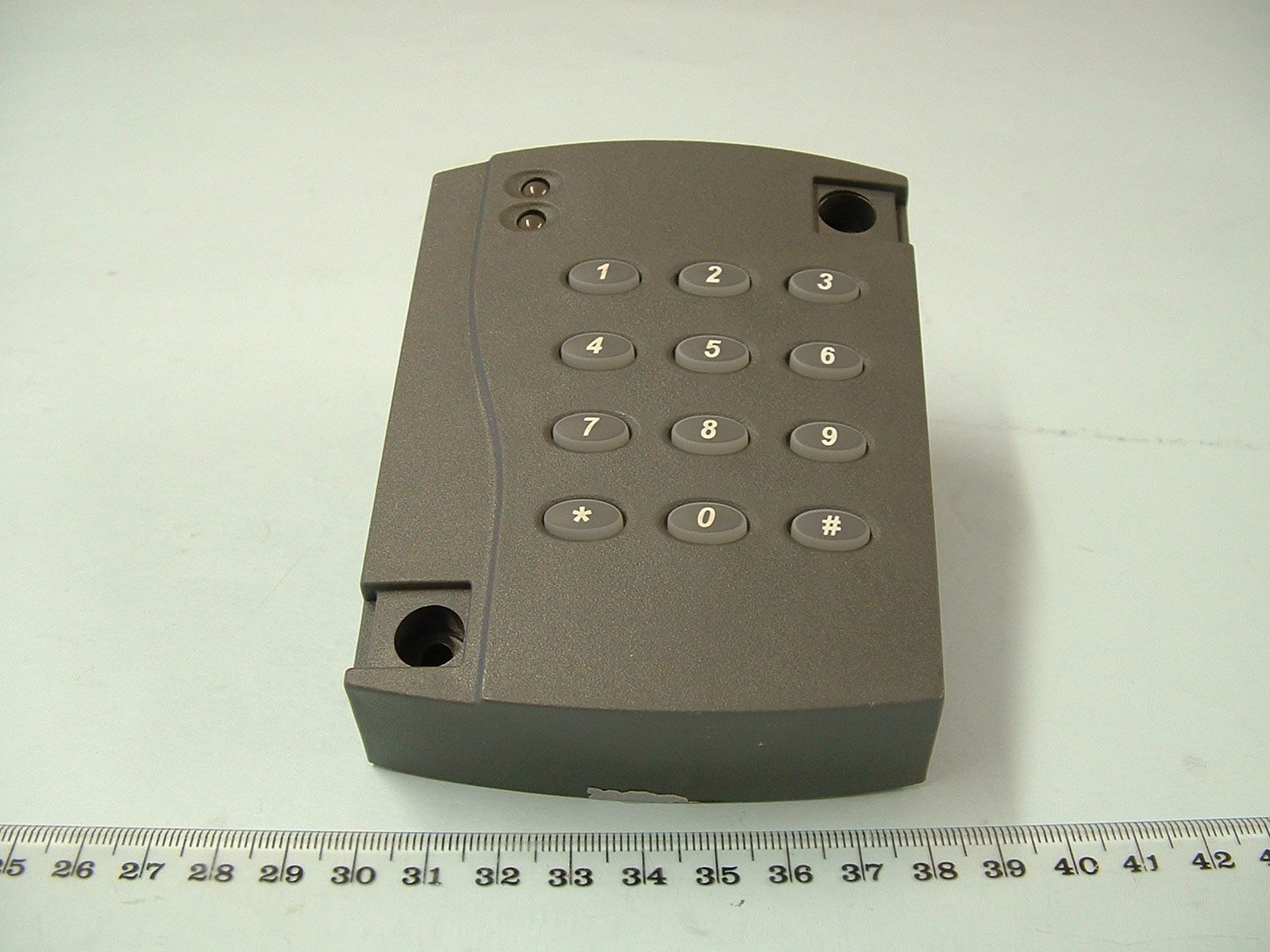
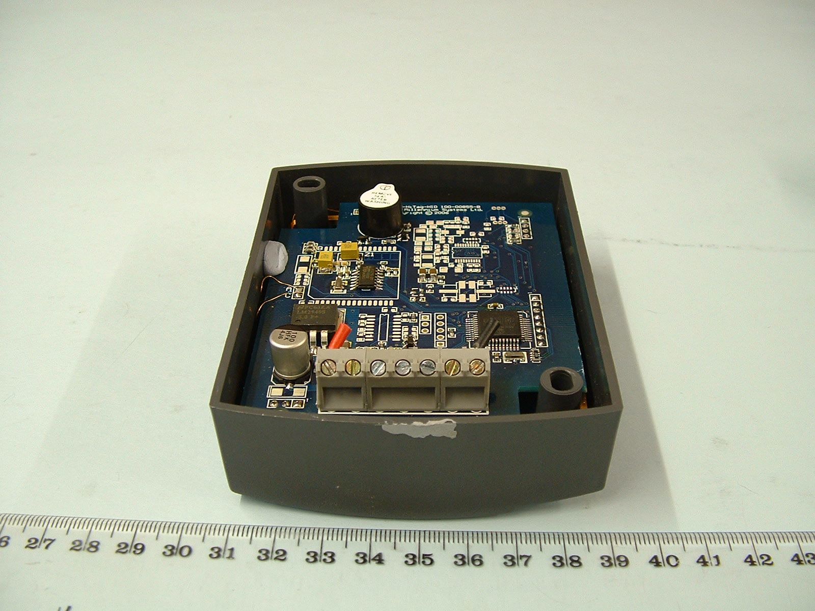
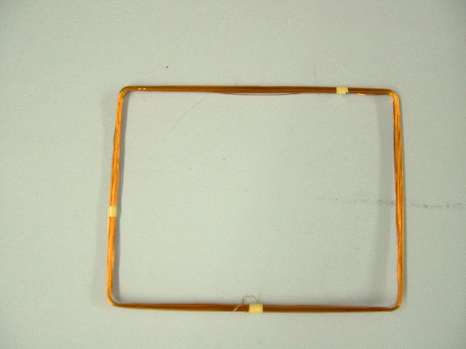
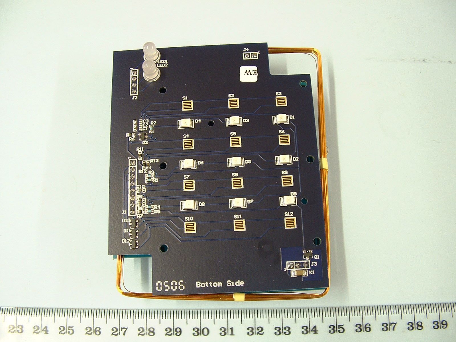
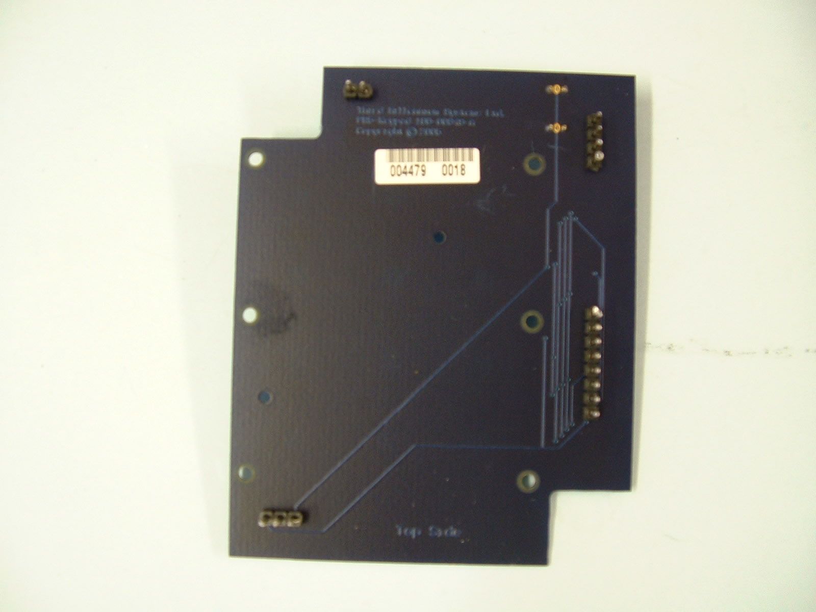
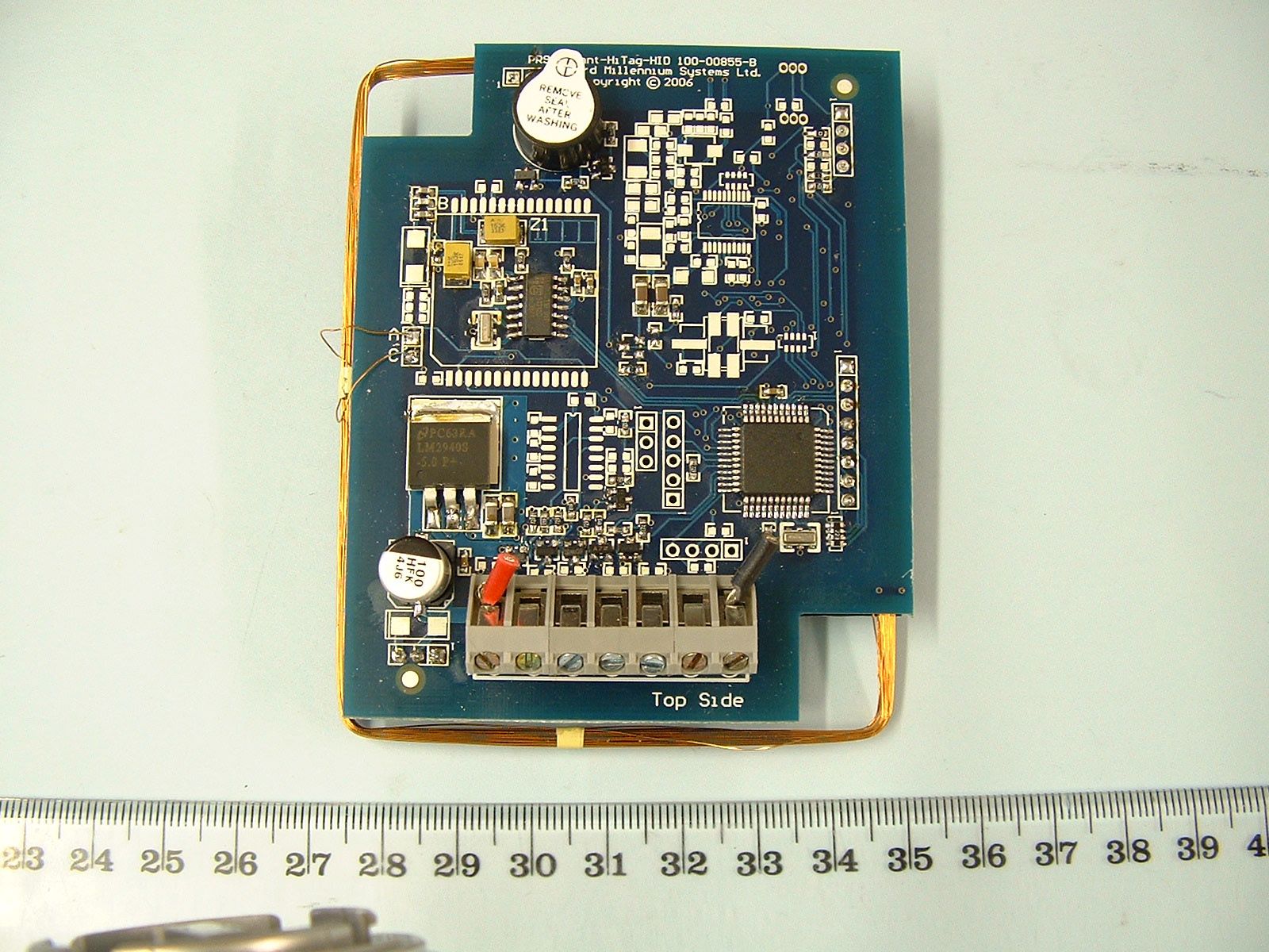
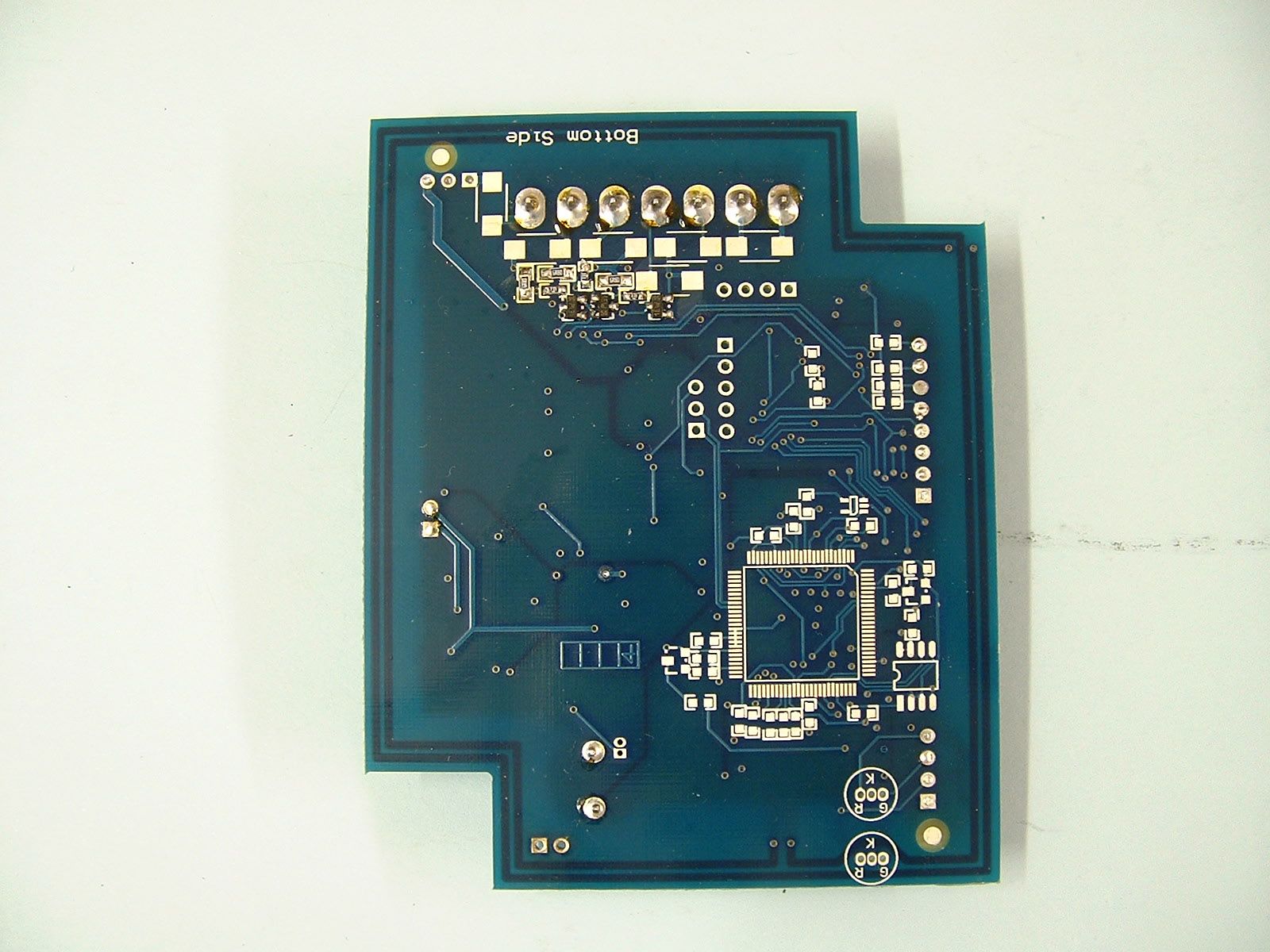
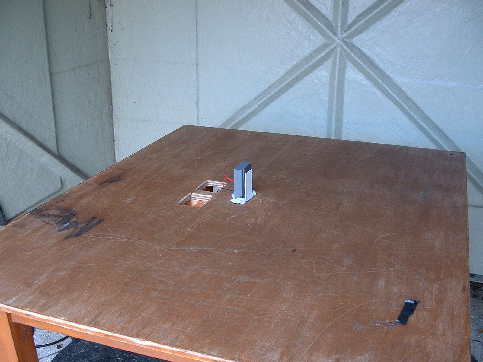
Document Text
Text extracted from the exhibit documents filed with the FCC. Open a document above to read the original.
Users Manual
Page 1 of 2 Third Millennium TM5 Series Programming Instructions December 2006 Third Millennium Systems Limited, 18/19 Torfaen Business Centre Panteg Way New Inn. Pontypool. NP4 0LS. T 0044 (0) 1495 751 992. F 0044 (0) 1495 757 448 Email [email protected] Web www.third-millennium-sys.com ENTERING PROGRAMMING MODE *00nnnn# Before you can configure the reader you must enter programming mode by using this command. You must enter the correct four-digit security PIN for the reader. The factory default is 1234. For example, to place a factory-configured reader into programming mode you should enter *001234#. If no keys are pressed, programming mode will timeout after 30 seconds without saving the changes you have made. SET PIN MODE *01n# This programming command allows you to set up how the reader handles keypad data. The reader is capable of outputting keypad data in a number of industry-standard formats. The following modes are supported: 0 – Disabled (i.e. no keypad output). 1 – HID 4-Bit Wiegand Burst (Factory Default) 2 – Dorado 8-Bit Wiegand Burst (also compatible with Indala) 3 – Mercury 8-Bit Wiegand Burst 4 – 1 Digit Clock & Data 5 – Dorado 8-Bit Burst 6 – 8 Digit Clock & Data 7 – 5 Digit Buffered to 26-Bit Wiegand Output (Sensor-26, Site Code = 0..255, Card No. = 0..65535) 8 – HID 32-Bit Wiegand Output (Site Code = 0..65535,Card No. = 0..65535) 9 – 7-Digit Buffered to 34-Bit Wiegand Output (Sensor-34, Site Code = 0..4095,Card No. = 0..1048575) For example, to set the reader to buffer keystrokes and output them in the industry-standard 26-bit format you should enter *017# once the reader has been placed into programming mode. SET AUDIBLE TONE ON CODE *02n# During the entry of a buffered PIN (PIN modes 7,8 and 9), you have the option of allowing the reader to issue a confirmation beep or an error triple-beep on entering the PIN. Once the reader has been placed into programming mode, enter *021# to enable the audible tone, *020# to disable the audible tone on PIN entry. By default, the audible tone is disabled. SET AUDIBLE TONE ON CARD *03n# During the entry of a buffered PIN (PIN modes 7,8 and 9), you have the option of allowing the reader to issue a confirmation beep or an error triple-beep on presenting the card. Once the reader has been placed into programming mode, enter *031# to enable the audible tone, *030# to disable the audible tone on PIN entry. By default, the audible tone is disabled. SET PROXIMITY READING *04n# This programming command allows you to disable transmission of the proximity card data by the reader. The reader will still beep to indicate that it has read the card. To disable transmission of the card data, enter *040# once the reader has been placed into programming mode. To enable transmission, enter *041#. By default, transmission is enabled. SET LED CONFIGURATION *05n# LED’s may be configured for the following modes. 0 – TM5 Standard LED Configuration 1 – Traffic Light, Plus Buzzer 2 – Mon LED, Plus Buzzer 3 – TM4 Standard LED Configuration 4 – TM4, Plus Buzzer SET SITE CODE *06nnnnn# Set the site code number that is combined with the card number read from the card and sent out as the complete card info message. The unit accepts site codes from zero to 65535 although the maximum valid value depends on the output format. SET SECURITY PIN *98oooonnnn# To ensure the security of the reader, it is important that a new security PIN is entered during installation to prevent unauthorised individual from reconfiguring the reader. For example, to change the factory default PIN of 1234 to 6767 you should enter *9812346767# one the reader has been placed into programming mode. SAVE CHANGES AND EXIT *99# Once you have set the configuration options you require for the reader, you must save them by entering this programming command. You must enter *99# to save the changes you have made to the reader’s configuration. Third Millennium Systems Limited, 18/19 Torfaen Business Centre Panteg Way New Inn. Pontypool. NP4 0LS. T 0044 (0) 1495 751 992. F 0044 (0) 1495 757 448 Email [email protected] Web www.third-millennium-sys.com Third Millennium TM5 Series Installation Instructions Page 2 of 2 December 2006 Introduction: The TM5 proximity keypad reader provides a convenient and easy-to-use means of transmitting RFID proximity card data and PIN data to an access control panel. The TM5 is quick and easy to install on any flat surface using the stainless steel fixing screws and wall plugs supplied, it can even be mounted direct to metal surfaces with no significant loss of read range. The durable push button keypad is back-lit to allow for operation at night, and a beep is emitted on every button press. A back-box is also available if surface-mount conduit cable entry is required. An optional buzzer (110+ dB) can be fitted in the back-box for applications where there are high levels of background noise. TM5 proximity keypad readers are available in many different output formats allowing interface with virtually all access control systems. Please ensure that the correct format is requested at time of order. Installation: The TM5 is designed to be mounted flush to the wall surface. Use the reader housing to mark out the position of the fixing screws, drill two holes suitable for the fixing screws and wall material. When drilling standard brick material a 6 mm drill should be used. If mounting on sheet material, glass, metal etc. the mounting arrangements will need to be modified to suit. Drill a hole roughly mid- way between the two mounting holes for the connection cable. Operation: When power is applied to the reader, the red LED will light and the beeper will sound to indicate the reader is fully functional. For optimum read range the card should be presented face-on to the reader. Typical read ranges are 15 cm when used with ISO proximity cards, and 8 cm with proximity keyfobs. Cabling: It is recommended that Belden 9536 screened cable, or equivalent, is u…
Text truncated - open the document above for the full version.
Test Report
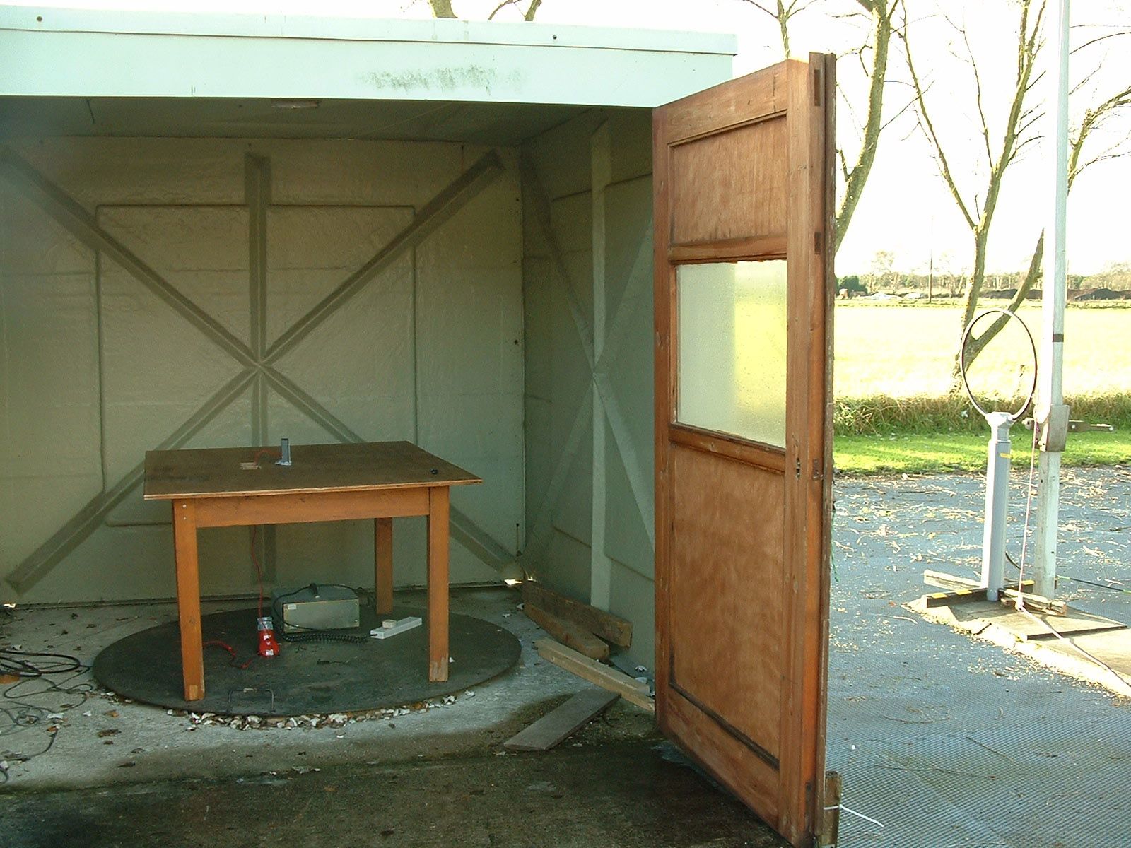
TRL COMPLIANCE LTD M OSS VIEW NIPE LANE UP HOLLAND WEST LANCASHIRE WN8 9PY UNITED KINGDOM T ELEPHONE +44 (0)1695 556666 FAX +44 (0)1695 557077 E-MAIL [email protected] www.trlcompliance.com 0728 FS 503099 TEST REPORT NO: RU1289/7353 COPY NO: 2 ISSUE NO: 1 FCC ID: UTJ-TM500 REPORT ON THE CERTIFICATION TESTING OF A THIRD MILLENNIUM SYSTEMS Ltd TM500 HITAG CARD READER WITH RESPECT TO FCC RULES CFR 47, PART 15.209 August 2006 INTENTIONAL RADIATOR SPECIFICATION TEST DATE: 23 rd – 29 th November 2006 TESTED BY: S Hodgkinson APPROVED BY: J Charters Radio Section Leader DATE: 19 th December 2006 Distribution: Copy Nos: 1. Third Millennium Systems Ltd 2. FCC EVALUATION LABORATORIES 3. TRL Compliance Ltd THIS DOCUMENT MAY BE REPRODUCED ONLY IN ITS ENTIRETY AND WITHOUT CHANGE RF335U iss02B RU1289/7353 Page 2 of 33 CONTENTS PAGE CERTIFICATE OF CONFORMITY & COMPLIANCE 3 APPLICANT’S SUMMARY 4 EQUIPMENT TEST CONDITIONS 5 TESTS REQUIRED 5 TEST RESULTS 6-10 ANNEX PHOTOGRAPHS A PHOTOGRAPH No. 1: Test setup PHOTOGRAPH No. 2: Transmitter front view PHOTOGRAPH No. 3: Transmitter rear view PHOTOGRAPH No. 4: Transmitter PCB track side PHOTOGRAPH No. 5: Transmitter PCB component side PHOTOGRAPH No. 6: Keypad PCB track side PHOTOGRAPH No. 7: Keypad PCB component side PHOTOGRAPH No. 8: Antenna APPLICANT’S SUBMISSION OF DOCUMENTATION LIST B EMISSION GRAPH(s) C BAND OCCUPANCY PLOT D POWERLINE CONDUCTION GRAPH(s) E TEST EQUIPMENT CALIBRATION F MEASUREMENT UNCERTAINTY G Notes: 1. Component failure during test YES NO [ ] [X] 2. If Yes, details of failure: 3. The facilities used for the testing of the product contain in this report are FCC Listed. 4. The contents of the attached applicants declarations and other supplied information are not covered by the scope of this laboratory’s UKAS or FCC accreditations’ and is provided in good faith. RF335U iss02B RU1289/7353 Page 3 of 33 CERTIFICATE OF CONFORMITY & COMPLIANCE FCC IDENTITY: UTJ-TM500 PURPOSE OF TEST: Certification TEST SPECIFICATION: FCC RULES CFR 47, Part 15.209 August 2006 TEST RESULT: Compliant to Specification EQUIPMENT UNDER TEST: TM500 Hitag Card Reader ITU: EMISSION CODE: 5K3K1N EQUIPMENT TYPE: Inductive Card Reader PRODUCT USE: Access Control CARRIER EMISSION: 1.48 μV/m @ 300m ANTENNA TYPE: Integral ALTERNATIVE ANTENNA: Not Applicable FREQUENCY OF OPERATION: 125.40 kHz CHANNEL SPACING: Not Applicable NUMBER OF CHANNELS: 1 FREQUENCY GENERATION: SAW Resonator [ ] Crystal [X] Synthesiser [ ] MODULATION METHOD: Amplitude [ ] Digital [X] Angle [ ] POWER SOURCE(s): +12Vdc TEST DATE(s): 23 rd – 29 th November 2006 ORDER No(s): 991720 APPLICANT: Third Millennium Systems Ltd ADDRESS: 18/19 Torean Business Park Centre Panteg Way Pontypool NP4 0LS TESTED BY: S Hodgkinson APPROVED BY: J Charters Radio Section Leader RF335U iss02B RU1289/7353 Page 4 of 33 APPLICANT’S SUMMARY EQUIPMENT UNDER TEST (EUT): TM500 Hitag Card Reader EQUIPMENT TYPE: Inductive Card Reader PURPOSE OF TEST: Certification TEST SPECIFICATION(s): FCC RULES CFR 47, Part 15.209 August 2006 TEST RESULT: COMPLIANT Yes No [X] [ ] APPLICANT’S CATEGORY: MANUFACTURER IMPORTER DISTRIBUTOR TEST HOUSE AGENT [X] [ ] [ ] [ ] [ ] APPLICANT’S ORDER No(s): 991720 APPLICANT’S CONTACT PERSON(s): Mr Peter Jones E-mail address: [email protected] APPLICANT: Third Millennium Systems Ltd ADDRESS: 18/19 Torean Business Park Centre Panteg Way Pontypool NP4 0LS TEL: +44 (0) 1495 751 992 FAX: +44 (0) 1495 757 448 EUT(s) COUNTRY OF ORIGIN: United Kingdom TEST LABORATORY: TRL Compliance Ltd. UKAS ACCREDITATION No: 0728 TEST DATE(s): 23 rd – 29 th November 2006 TEST REPORT No: RU1289/7353 RF335U iss02B RU1289/7353 Page 5 of 33 EQUIPMENT TEST / EXAMINATIONS REQUIRED 1. TEST/EXAMINATION RULE PART DETECTOR APPLICABILITY Intentional Emission Frequency: 15.209(a) Average Yes Intentional Emission Field Strength: 15.209(a) Average Yes Intentional Emission Band Occupancy: 15.215(c) Peak Yes Intentional Emission ERP (mW): - - No Spurious Emissions – Conducted: 15.207 Quasi Peak Average Yes Spurious Emissions – Radiated <1000MHz: 15.209 Quasi Peak Average Yes Spurious Emissions – Radiated >1000MHz: - - No Maximum Frequency of Search: 15.33 - Yes Antenna Arrangements Integral: 15.203 - Yes Antenna Arrangements External Connector: 15.204 - Yes Restricted Bands: 15.205 - Yes Extrapolation Factor: 15.31(f) - Yes 2. Product Use: Access Control 3. Emission Designator: 5K3K1N 4. Duty Cycle: <100% 5. Transmitter bit or pulse rate and level: 5200bps 6. Temperatures: Ambient (Tnom) 10 o C 7. Supply Voltages: Vnom +12Vdc Note: Vnom voltages are as stated above unless otherwise shown on the test report page Single channel [X] Two channel [ ] 8. Equipment Category: Multi-channel [ ] Narrowband [ ] Wideband [X] 9. Channel spacing: RF335U iss02B RU1289/7353 Page 6 of 33 TRANSMITTER TESTS TRANSMITTER SPURIOUS EMISSIONS – RADIATED – PART 15.209 Ambient temperature = 10 o C(<1GHz) 3m measurements <30MHz [X] Relative humidity = 54% (<1GHz), 10m measurements <30MHz [X] Conditions = Open Area Test Site (OATS) 3m measurements <1GHz [X] Supply voltage = +12Vdc 300m extrapolated from 3m [X] Channel number = 1 300m extrapolated from 10m [X] FREQ. (MHz) MEAS. Rx. (dBμV) CABLE LOSS (dB) ANT FACTOR (dB/m) FIELD STRENGTH (dBμV/m) EXTRAP. FACTOR (dB) FIELD STRENGTH (μV/m) 0.009MHz - 0.49MHz No Significant Emissions Within 20 dB of the Limit 0.49MHz - 1.705MHz No Significant Emissions Within 20 dB of the Limit 1.705MHz - 30MHz No Significant Emissions Within 20 dB of the Limit 30MHz - 88MHz No Significant Emissions Within 20 dB of the Limit 88MHz - 216MHz No Significant Emissions Within 20 dB of the Limit 216MHz - 960MHz No Significant Emissions Within 20 dB of the Limit 960MHz - 1GHz No Significant Emissions Within 20 dB of the Limit 1GHz - 5GHz No Significant Emissions Within 20 dB of the Limit 0.009 MHz to 0.49 MHz2400/f(kHz) μV/m @ 300m 0.49 MHz to 1.705 MHz24000/f(kHz) μV/m @ 30m 1.705MHz to 30MHz 30μV/m @ 30m 30MHz to 88MHz 100μV/m @ 3m 88MHz to…
Text truncated - open the document above for the full version.
Contact Information
Applicant
Peter Lionel Jones(Mr.)
Technical Contact
Third Millennium Systems Ltd.Allen Berndt
[email protected]+44 1495 751992
18/19 Torfaen Business Centre · Pontypool · United Kingdom
Non-Technical Contact
Third Millennium Systems Ltd.Peter Jones
[email protected]+44 1495 751992
Test Firm
TRL Compliance LtdJohn Charters
Technical Specifications
| # | Rule Parts | Frequency Range | Power Output | Emission |
|---|---|---|---|---|
| 1 | 15C | 0.123205 MHz - 0.128462 MHz | - | 5K3K1N |
Other Applications from Third Millennium Systems Ltd.

UTJ-PRX60BLE
Jul 27, 2020Access Control Reader, Model RX190B/ RX1K90B
Equipment Class
DXX - Part 15 Low Power Communication Device Transmitter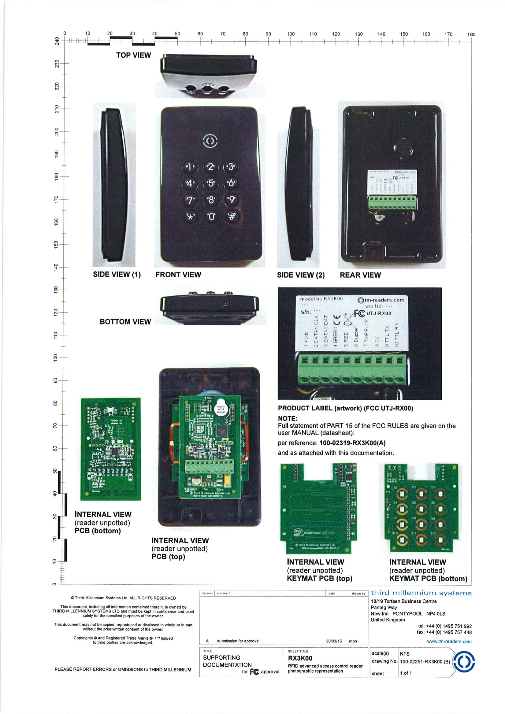
UTJ-RX00
May 31, 2015125kHz Access Control Reader
Equipment Class
DCD - Part 15 Low Power Transmitter Below 1705 kHz
UTJ-RX80PLUS
May 28, 2015125KHz and 13.56MHz Access Control Reader
Equipment Class
DCD - Part 15 Low Power Transmitter Below 1705 kHz
UTJ-PRX6FP
Jan 22, 2015Fingerprint Reader RX660
Equipment Class
DXX - Part 15 Low Power Communication Device Transmitter