UU7DCTX4Outdoor Sensor
Formation Limited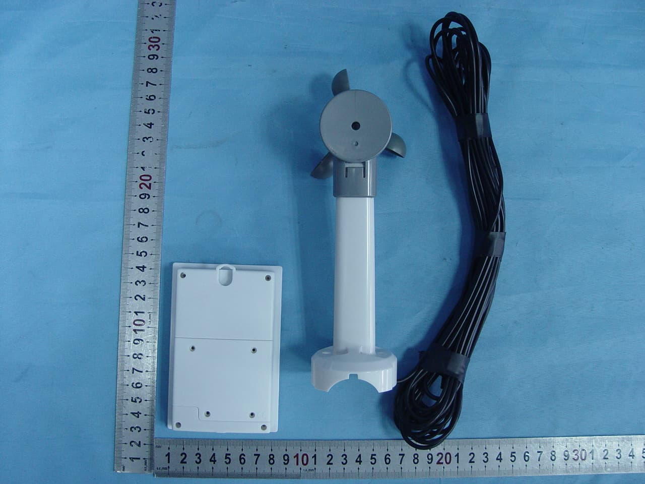
Click to zoom
Application Details
- Equipment Class
- DSC - Part 15 Security/Remote Control Transmitter
- Date of Grant
- Apr 18, 2007
- Application Purpose
- Original Equipment
- Date of Application
- Apr 18, 2007
- Equipment Note
- Outdoor Sensor
- Frequency Range
- 433.92000000 - 433.92000000
- Company
- Formation Limited
- Country
- Hong Kong
Documents & Files
Document Text
Text extracted from the exhibit documents filed with the FCC. Open a document above to read the original.
Users Manual
1608 Fourth Street Berkeley, CA 94710 tel: (510) 558-6441 Filename: DIscAdult _ weather4 _ STX7500 _ Instr.indd DiscAdult_Weather 4_STX7500_inst1 1 2/2/07 2:49:16 PM 2 3 The WeatherTech STX7500 is our top-line home weather station. It has comprehensive weather data for you — including 30-hour bar ometric pressure, forecasts, dew point, wind chill, tidal reports, sunrise, moonrise and more. The STX7500 also has elegant info delivery, with a clear, easy to read blue screen s howing scrolling weather alerts. Set up is simple 1. Place the main station in your home — the bright back-light makes it a perfect alarm clock, or the mounting brackets make it perfect for any wall. 2. Program the main station.3. Place the remote sensor outside your home.4. Access your weather data anytime at a glance. Set up your remote sensorYour first step is to set up the STX7500 remote sensor. The remote device will read external conditions and automatically send t hem to the main station inside your home. 1. Open up the back panel of the remote sensor and add two AA (1.5V) batteries (not included).2. Just above the batteries is a switch which lets you choose which “channel” to broadcast on. Unless you plan to have multiple remote devices (which is unlikely), just keep the setting on channel 1. 3. Find the button which is marked C/F, for Celsius or Fahrenheit, located on the back of the unit. Choose the temperature metri c that you would prefer by pressing the button until your preference is displayed. Set up your anemometerYour second step is to set up your STX7500 wind anemometer. 1. Mount your wind anemometer near your outdoor sensor.2. Attach it to your outdoor sensor by connecting the included cable. Includes• STX7500 Weather station• 1 Remote temperature and humidity sensor • 1 Wind anemometer• 1 AC Adapter – adapter rated 120V AC, 60Hz input, 6.0 V DC, 500mA output Air pressure tendency arrow Scrolling forecast Indoor temperature Indoor humidity WWVB Reception indicator Forecast icon Outdoor (remote) temperature Outdoor (remote) humidity Radio-controlled time Outdoor wind chill Barometric air pressure Tide indicator Moon phase indicator Sunrise and sunset time for selected areas Moonrise and moonset time for selected areas Outdoor wind speed Day and date Outdoor dew point Outdoor heat index Barometric history graph Touch panel functionality DiscAdult_Weather 4_STX7500_inst2-3 2-3 2/2/07 2:49:24 PM 4 5 Set up your main stationYour third step is to set up and program your STX7500 main station. You will set the current weather, location, and other setti ngs. Programming the main unit1. Open up the battery panel of the main station device and add four AA (1.5V) batteries (not included). The unit can also be op erated using the supplied AC adaptor. Plug the barrel end of the adaptor into the jack located on the bottom of the STX7500; plug the other end into a wall outlet. 2. Main unit will light up entire display, and a sound will tell you unit is defaulting to initial settings.3. DO NOT TOUCH ANY BUTTONS FOR 10 MINUTES, WHILE THE STATION LOOKS FOR THE OUTDOOR SENSOR AND SCANS FOR THE WWVB SIGNAL.4. The two devices will begin communicating in this time. You should see the main station pick up a temperature and channel read ing. This shows that the two devices are in communication. 5. Place the remote device outside the house. a. Fog and mist will not harm your remote sensor, but direct rain should be avoided.b. The sensor has a range of 30 meters, but intervening walls will lower that number. An outdoor wall or window may have a 20 to 30 foot resistance. c. Consider mounting your device on an outside wall, directly opposite to the room where you plan to have your main station. 6. Once you have placed your outdoor sensor, check the main station to make sure the two devices are still communicating. Setting the WeatherTo begin, you must input the current weather conditions outside your house. This is because the forecaster technology works usi ng current conditions to predict future conditions. 1. Immediately after set up, the weather icon will be flashing for 15 seconds. 2. Press “+” or “-” on the back of the unit to input the correct weather outside. It is recommended that you set your first forec ast based on a local weather report. 3. Once you have established current weather, press the “REL/ABS” button, located on the back of the unit, again to exit4. The main station will start to forecast 6 hours after the current weather is entered . 5. When the main station begins forecasting, you will see one of 6 different symbols in the weather forecast. This is your forec ast for your area. The forecast is for 6 hours ahead. 6. At any time you can reset the weather forecast by holding down the “REL/ABS” button for 3 seconds. Then follow steps 2 and 3 again to set the new forecast. 7. When setting the weather, please note: a. If the outdoor sensor reads below 0°C and you have input the weather to “rain” or “heavy rain” then your main station will di splay snow b. The weather conditions should be reset if you change the altitude. Setting Clock AutomaticallyAfter the main station has finished searching for the remote sensor, it will proceed to scan for the “WWVB” signal — this is an atomic clock transmission which is sent all across the United States.1. Buttons will not function while station is scanning for WWVB time signal.2. While scanning the RCC icon will flash on the main station. 3. When the RCC icon stops flashing, the main station has successful updated with the correct time. a. Your main station will automatically rescan for WWVB time signal every night at 2:00 a.m.. If the first attempt fails, statio n will scan again at 3:00, 4:00, and 5:00 a.m. b. To manually start a new time scan, press and hold the “RCC” button, located on the back of the unit, for 3 seconds. 4. If the reception fails, the RCC icon will disappear. a. If reception fails, the main station will attempt to rescan for signal 4 times. Each time …
Text truncated - open the document above for the full version.
Operational Description
STX7500-TX Operational Description Transmit Frequency: 433.92MHz Modulation Type: ASK This is a LCD display thermometer and humidity for house hold application. The unit use 2 pcs of 1.5V battery in-series connection give 3V supply. Devices operated under the provisions of this paragraph shall be provided with a means for automatically limiting operation so that the duration of each transmission shall not be greater than one second and the silent period between transmissions shall be at least 30 times the duration of the transmission. The function of the unit is to regularly measure its surrounding wind speed, temperature and humidity at its point of location and transmit the data using wireless 433MHz to a standing alone receiving unit. The data would be displayed on the receiving units LCD. For all description please read the enclosed user instruction manual.
Test Report
Page 1 of 27 FCC ID: UU7DCTX4 ACCURATE TECHNOLOGY CO. LTD REPORT NO. ATE20070808 APPLICATION CERTIFICATION On Behalf of Formation Limited Outdoor Sensor Model No.: STX7500 FCC ID: UU7DCTX4 Prepared for : Formation Limited Address : Suit 915-918, 9/F Corporation Square, 8 Lam Lok St. Kowloon Bay, Kowloon, Hong Kong Prepared by : ACCURATE TECHNOLOGY CO. LTD Address : F1, Bldg. A, Changyuan New Material Port, Keyuan Rd. Science & Industry Park, Nanshan, Shenzhen, Guangdong P.R. China Tel: (0755) 26503290 Fax: (0755) 26503396 Report Number : ATE20070808 Date of Test : April 05, 2007 Date of Report : April 12, 2007 Page 2 of 27 FCC ID: UU7DCTX4 ACCURATE TECHNOLOGY CO. LTD REPORT NO. ATE20070808 TABLE OF CONTENTS Description Page Test Report Certification 1. GENERAL INFORMATION .......................................................................................................... 4 1.1. Description of Device (EUT)....................................................................................................................4 1.2. Description of Test Facility ......................................................................................................................4 1.3. Measurement Uncertainty.........................................................................................................................4 2. MEASURING DEVICE AND TEST EQUIPMENT ..................................................................... 5 3. THE FIELD STRENGTH OF RADIATION EMISSION ............................................................ 6 3.1. Block Diagram of Test Setup....................................................................................................................6 3.2. The Field Strength of Radiation Emission Measurement Limits..............................................................6 3.3. Configuration of EUT on Measurement ...................................................................................................7 3.4. Operating Condition of EUT ....................................................................................................................7 3.5. Test Procedure ..........................................................................................................................................7 3.6. The Field Strength of Radiation Emission Measurement Results ............................................................8 4. 20DB OCCUPIED BANDWIDTH .................................................................................................. 9 4.1. Block Diagram of Test Setup....................................................................................................................9 4.2. The Bandwidth of Emission Limit According To FCC Part 15 Section 15.231(c) ..................................9 4.3. EUT Configuration on Measurement .....................................................................................................10 4.4. Operating Condition of EUT ..................................................................................................................10 4.5. Test Procedure ........................................................................................................................................10 4.6. Measurement Result ...............................................................................................................................11 5. DURATION TIME AND SILENT PERIOD MEASUREMENT............................................... 12 5.1. Block Diagram of Test Setup..................................................................................................................12 5.2. Duration Time and silent period measurement according to FCC Part 15 Section 15.231(e) ................12 5.3. EUT Configuration on Measurement .....................................................................................................13 5.4. Operating Condition of EUT ..................................................................................................................13 5.5. Test Procedure ........................................................................................................................................13 5.6. Measurement Result ...............................................................................................................................14 6. AVERAGE FACTOR MEASUREMENT .................................................................................... 15 6.1. Block Diagram of Test Setup..................................................................................................................15 6.2. Average factor Measurement according to ANSI 63.4: 2003.................................................................15 6.3. EUT Configuration on Measurement .....................................................................................................16 6.4. Operating Condition of EUT ..................................................................................................................16 6.5. Test Procedure ........................................................................................................................................16 6.6. Measurement Result ...............................................................................................................................17 APPENDIX I ( TEST CURVES) (9pages) Page 3 of 27 FCC ID: UU7DCTX4 ACCURATE TECHNOLOGY CO. LTD REPORT NO. ATE20070808 Test Report Certification Applicant : Formation Limited Manufacturer : Carrin Electronics Co., Ltd. EUT Description : Outdoor Sensor (A) MODEL NO.: STX7500 (B) SERIAL NO.: N/A (C) POWER SUPPLY: DC 3.0V (AA Battery ̄2) Measurement Procedure Used: FCC Rules and Regulations Part 15 Subpart C Section 15.231: 2006 & ANSI 63.4: 2003 The device described above is tested by ACCURATE TECHNOLOGY CO. LTD to determine the maximum emission levels emanating from the device. The maximum emission levels are compar…
Text truncated - open the document above for the full version.
Contact Information
Applicant
SAM ASHWIN SAMTANI(Supply Chain Director)
Test Firm
Accurate Technology Co., Ltd.Sean Liu
Technical Specifications
| # | Rule Parts | Frequency Range | Power Output |
|---|---|---|---|
| 1 | 15.231(e) | 433.92 MHz - 433.92 MHz | - |
Other Applications from Formation Limited
UU7CEW220T
Dec 15, 200949MHz WIRELESS SPEAKER
Equipment Class
DXX - Part 15 Low Power Communication Device Transmitter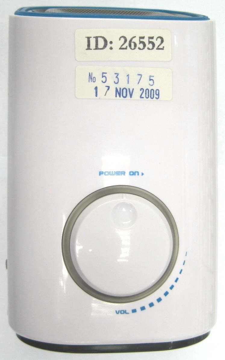
UU7CEW220R
Dec 15, 200949MHz WIRELESS SPEAKER
Equipment Class
CYY - Communications Receiver used w/Pt 15 Transmitter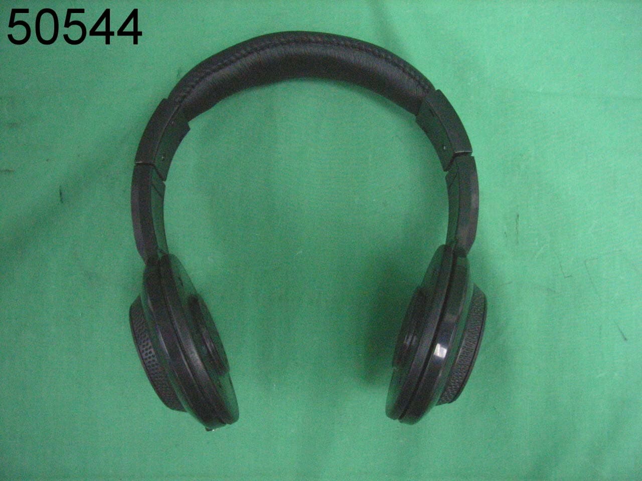
UU7CEW100R
Sep 25, 2008Wireless Headphone- Receiver
Equipment Class
CYY - Communications Receiver used w/Pt 15 Transmitter
UU7-TT072-U7F-TX
Apr 25, 2007RF MEAT THERMOMETER
Equipment Class
DSC - Part 15 Security/Remote Control Transmitter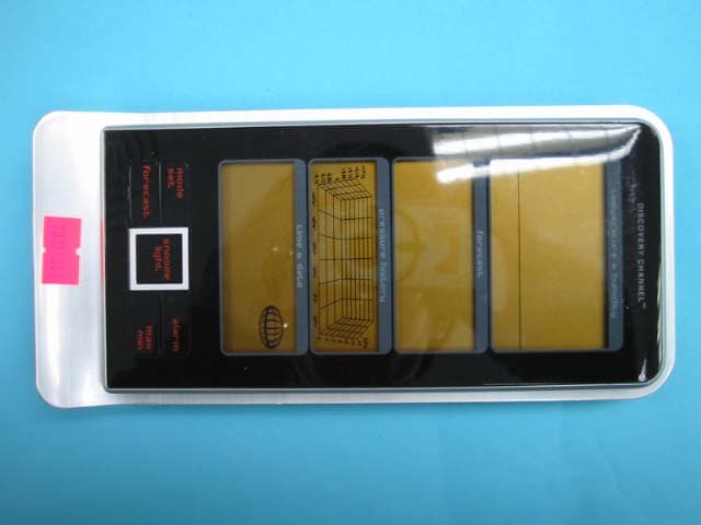
UU7DCRX2
Apr 22, 2007Receiver for Outdoor Sensor
Equipment Class
CYY - Communications Receiver used w/Pt 15 Transmitter