UUM10156V10Vu Qube
KING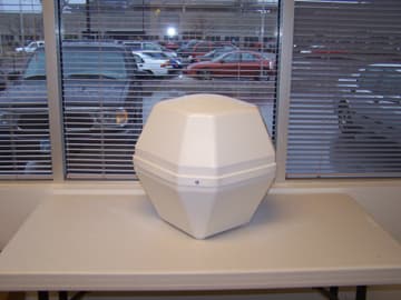
Click to zoom
Application Details
- Equipment Class
- DTS - Digital Transmission System
- Date of Grant
- Jan 25, 2007
- Application Purpose
- Original Equipment
- Date of Application
- Jan 25, 2007
- Equipment Note
- Vu Qube
- Frequency Range
- 2402.00000000 - 2470.00000000
- Company
- KING
- Country
- United States
Documents & Files
Document Text
Text extracted from the exhibit documents filed with the FCC. Open a document above to read the original.
Users Manual
Installation and Operating Manual Made in the USA TM Mobile Satellite TV Antenna With FastFind Remote Vu Qube V10_06 2 1. INTRODUCTION and BACKGROUND................................................ 3 2. COMPENT OVERVIEW and SPECIFICATIONS................................. 4 3. FCC USER’S INFORMATION....................................................5 3. INSTALLATION .............................................................................. 6-8 4. OPERATION ....................................................................................... 9 6. TROUBLESHOOTING ........................................................................ 10 7. MAINTENANCE .................................................................................. 10 8. LIMITED WARRANTY ........................................................................ 10 Vu Qube V10_06 3 Introduction Congratulations on your purchase of the Vu Qube V10. The Vu Qube V10 is equipped with a FastFind remote enabling you to quickly position the Vu Qube antenna from inside your vehicle. The Vu Qube V10 is compatible with any service provider such as DIRECTV ®, DISH Network ® or Bell ExpressVu. This manual includes a: • Brief background on satellite television • Components overview • Installation diagrams and instructions • Operating Instructions Technical Support Phone: (866) 802-2228 Email: [email protected] Web: www.vuqube.com Background Satellites used for television signals are 22,300 miles (37,000 km) above the earth’s equator. The purpose of the Vu Qube is to acquire the signal traveling that great distance and transmit the signal to your digital receiver in your vehicle so you can watch TV anywhere you park. Satellite television, like other communications relayed by satellite, starts with a transmitting antenna located at an uplink facility on Earth. The uplink dish is pointed toward a specific satellite and the uplinked signals are transmitted. The signal transmitted to the satellite is within a specific frequency range and is received by one of the transponders tuned to that frequency range aboard that satellite. The transponder then transmits the signals back to Earth but at a different frequency band (to avoid interference with the uplink signal). The leg of the signal path from the satellite to the receiving Earth station, in this case the Vu Qube, is called the downlink. The downlinked satellite signal, quite weak after traveling the great distance is received by the Vu Qube antenna, which reflects the weak signal to a focal point that gets transferred to a feedhorn. The receiving antenna must have a clear view, without obstruction, of the southern sky to maximize signal acquired. This signal is then amplified and converted by the LNBf (Low-noise block converter feed) to a signal that is sent via a co-axial cable to the receiver. Once the signal is transmitted from the Vu Qube to your receiver, you can enjoy all of your programming in your vehicle just like at home! A Quick Reference guide is included with Operating Instructions & Elevation information that we suggest you keep with the Vu Qube Controller or near your Satellite TV receiver. The Satellite Broadcast Market is changing and expanding. The information in this manual was accurate at the time of printing. If the Vu Qube does not operate as shown in this manual, please call Wallace Technologies at 1-866-802-2228 or email us at [email protected] . Vu Qube V10_06 4 Vu Qube V10 Component Overview Manual Quick Reference Guide Vu Qube Antenna Vu Qube FastFind Remote RG6 Coaxial Cable (20’) Mounting Kit (Purchased Separately) Kit shown is Model Number 31100 ***You will need to supply your own fasteners to attach a Vu Qube bracket to your vehicle. Depending on the Cab material, fasteners such as lag screws, well nuts, sheet metal screws, toggle bolts and T anchors may be used, and should always be used in combination with compatible sealant to environmentally seal the holes after installation.*** Items needed to watch TV Satellite TV service Satellite TV receiver Television Tools needed for installation Drill and drill bits Tape measure Screw drivers and Wrenches Adhesive sealant (compatible with vehicle material) Fasteners to secure Components and wiring SPECIFICATIONS Height: 17.5” Width: 16” Weight: 10.5 lbs Range: US/Southern Canada Compatibility: DirecTV, Dish Network, Bell ExpressVu, Free-to-air receivers Operating Temp: May experience difficulty positioning antenna when temperatures are below 0°F Vu Qube V10_06 5 FCC User Information Main Components Vu Qube V10 Antenna Vu Qube V10 Remote Part #: VQV10 FCC ID: UUM10156V10 IC: 6873A -10156V10 This devise complies with Part 15 of the FCC rules. Operation is subject to the following two conditions: 1) This devise must not cause harmful interference, and 2) This devise must accept interference received including interference that may cause undesired operation. Part #: VQV10R FCC ID: UUM10157V10 IC: 6873A -10157V10 This devise complies with Part 15 of the FCC rules. Operation is subject to the following two conditions: 1) This devise must not cause harmful interference, and 2) This devise must accept interference received including interference that may cause undesired operation. The Vu Qube V10 and Vu Qube V10 remote have been tested and found to comply with the limits for a Class B digital device, pursuant to part 15 of the FCC Rules. These limits are designed to provide reasonable protection against harmful interference in a residential installation. This equipment generates, uses, and can radiate radio frequency energy and, if not installed and used in accordance with the instruction, may cause harmful interference to radio communications. However, there is no guarantee that the interference will not occur in a particular installation. If this equipment does cause harmful interference to radio or television reception, which can be determined by turning the equipment off and on, the user is encouraged to try to corre…
Text truncated - open the document above for the full version.
Block Diagram
55 44 33 22 11 D D C C B B A A Title & Block Diagram Description of Change Page Rev Date Description 1 ECO Number Table of Contents Controller Logic Product Development Confidential PowerRadioMotor Control 2345 NET NAMES IN GREEN TEXT ARE NETS THAT ARE NOTDIRECTLY CONNECTED WITH A VISIBLE WIRE ON SINGLESCHEMATIC PAGE, BUT USE THIS CONVENTION TO MAKETHE SCHEMATIC EASIER TO READNET NAMESNET NOTES IN BLACK TEXT INDICATE A PARTICULARFUNCTIONALITY OF A SPECIFIC NET, IT IS NOT A NETNAME MERELY TEXT AND HAS NO AFFECT ON THEDRC.NOTES IN GREEN TEXT ARE GENERAL DESIGN ORSCHEMATIC NOTESNOTE:COLOR LEGENDNET NOTENOTES IN RED TEXT ARE PCB LAYOUTRECOMMENDATIONS OR GUIDELINESLAYOUT NOTE: Analog / Misc 6 27-JUL-2006 Preliminary 0.11.0 9-AUG-2006 First PrototypeRev A Release 2.0 3-OCT-2006 30-OCT-2006 Rev B Release 3.0 GPIO Coax Azimuth,Tilt,CurrentSense, LNBVoltage,Super CapVoltage,SignalStrength ADC ConfigJumpers/LEDs BulkCapacitor Radio IC2402-2470MHz 8VSupply Microcontroller OverallSystem SPI LNB Coax PowerTap GPIO MotorController Receiver 3.3VSupply Wallace TechnologyVuQube X100Main Board Internal 8MHz Oscillator External 16MHz Crystal 2402-2470MHz A Title & Block DiagramC 1 <Orgaddr1> 6 <number> Page Modify Date = Tuesday, December 12, 2006 411 WASHINGTON AVE. N Title Size Number Project Sheet of PHONE: (612) 672-9495MINNEAPOLIS, MN 55401FAX: (612) 672-9489 LOGIC PRODUCT DEVELOPMENT Rev
Cover Letter(s)
TÜV America Inc. Phone: (651) 631-2487 1775 Old Highway 8 NW Fax: (651) 638-0285 Suite 104 E-mail: [email protected] New Brighton, MN 55112 www.TUVamerica.com Management Service • Product Service • Industry Service • Automotive • BABT TÜV America Inc. is a subsidiary of TÜV SÜD Group. 17 January 2007 American TCB 6731 Whittier Avenue McLean VA 22101 RE: Wallace Technologies Response to 15 January 2007 Comments FCC ID: UUM10156V10 In response to your comments on the above submittal from 15 January 2007. 1. ATCB Comments: Regarding equipment labeling for Canada, the label must contain 3 items. The label should contain the applicant, Certification Number, and model number as certified and shown on the IC form. Currently the label does not show a complete certification number, model number as shown on the form, or the applicant. Please correct. RESPONSE: Revised label has been uploaded. 2. ATCB Comments: Being a device under 15.247 with RF exposure requirements, the users manual should generally instruct the user no to co-locate the device with other transmitters. RESPONSE: Revised manual has been uploaded. 3. ATCB Comments: Please provide calculations and information to show how final output power was measured and calculated. Was this radiated? Did it use the FCC required far field equations? RESPONSE: The output power and spurious emissions had to be made as a radiated measurement. Attempts to connect rf connector to the EUT rf output were unsuccessful. We used OET 63 formula P(eirp in watts) = 0.3 Esquared (field strength in v/m), using unity antenna gain in calculation, 3 meters distance. This has been put in both reports on output power page and revised reports have been uploaded. 4. ATCB Comments: A large difference is noted between peak and average readings. This suggests that the signals may have actually had a duty cycle associated with them. If so, the average should have actually been derived using worse case duty cycle calculations. Please review/explain/correct as necessary. RESPONSE: The average measurements are made using a 1 MHz resolution bandwidth and a 10 Hz video bandwidth per FCC guidelines. This has been put in both reports on Appendix C page. The mfr. instructed us the worst case mode was being tested. Since measured levels are compliant, and believed to be worst case, we did not pursue duty cycle calculations. 5. ATCB Comments: Cited output power given on the 731 form is about 9 dB below the operational description which cites output power is maximum of +4 dBm. Was device properly operating and/or configured at maximum output power? Was RBW > 6 dB bandwidth with VBW > RBW? FCC expects device to be at maximum output power. Please review/correct as necessary. RESPONSE: The level on the 731 was erroneously put on as the erp, eirp would be 700 microwatts, or -1 dBm. This would be close to typical value in operating description of 0 dBm. We can revise Form 731. Is this acceptable, or do we need Wallace to state that their product will not be putting out 4 dBm (maximum on chip spec). 6 dB bw = 542 kHz, rbw used to make peak measurement was 1 MHz. TÜV America Inc. Phone: (651) 631-2487 1775 Old Highway 8 NW Fax: (651) 638-0285 Suite 104 E-mail: [email protected] New Brighton, MN 55112 www.TUVamerica.com Management Service • Product Service • Industry Service • Automotive • BABT TÜV America Inc. is a subsidiary of TÜV SÜD Group. 6. ATCB Comments: It is uncertain if bandedge emissions for bandedge restricted bands has been provided. Please review/explain as necessary. RESPONSE: P. 22 of 38 demonstrates low channel is >-20dBc at 2400 MHz. I have edited P. 24 of 38 to demonstrate high channel measurement is below 15.209 limit at 2483.5 MHz. 7. ATCB Comments: It does not appear that RX emissions per RSS-210 and RSS-GEN have been provided. Please explain/review/correct. RESPONSE: Receiver is always on, is covered in spurious emission testing. The above referenced documents have been uploaded to the website at the same time as this response. Please let us know if anything further is required. Susan L Rupp, Technical Writer TÜV America Inc Tel: 651 638 4585 / Fax: 651 638 0298 [email protected]
Cover Letter(s)
Hi Tim OK, I think I have the label and the app matching - the model for the Vu Qube is VQV10 and the model for the Remote is VQV10R. This is the same on both label and RSP-100 for both application. Uploading now. I'll get the manual revised and reuploaded. The rest of your comments have been forwarded to Joel to answer. Thank you, Sue From: Timothy R. Johnson [mailto:[email protected]] Sent: Wednesday, January 17, 2007 11:38 PM To: Rupp, Susan Subject: RE: Wallace applications ATCB004406 & ATCB004405 status request Susan, 1) The model on the IC for and the device still does not match. Please confirm how we are listing this device and ensure the labels match. 2) the manual co-location statement should identify that the non-colocation is to meet the FCC's RF exposure requirements, or must be stated in a firm manner such as "this device must not be co-located with other transmitters to ensure compliance with FCC RF exposure requireements", etc. 3) Regarding the response regarding average measurements to previous comment 4, the concern is that the 10 Hz method is only valid on signals that are CW in nature, or at least that the Ton time is > 1/VBW. Yes the device should be tested for worse case mode, but the validity of the measurement depends on the behavior of the carrier and the settings used during the test. If the device was pulsed, a 10 Hz method is likely not acceptable. Further information is necessary to ensure compliance. Note the previous comment was ATCB Comments: A large difference is noted between peak and average readings. This suggests that the signals may have actually had a duty cycle associated with them. If so, the average should have actually been derived using worse case duty cycle calculations. Please review/explain/correct as necessary. 4) Regarding previous issue 5, we need confirmation that device tested was a maximum expected output power. 5) If applicable from response to issue 5, please correct 731. 6) Please ensure final output power result is in the report. It appears that only a margin and field strengths are shown. 7) Output power still appears to show 31.5 dB margin, which does not match data on pages 17-18 as cites. Please review. Tim At 12:00 PM 1/17/2007 -0500, you wrote: Hi Tim I've uploaded the attached response and referenced revised documents for the Vu Qube, remote will follow shortly. Wallace asked me to ask about status as they are very anxious for grants and certificates on these products. Subject: RE: Wallace applications ATCB004406 & ATCB004405 status request From: "Rupp, Susan" <[email protected]> To: Timothy R. Johnson <[email protected]> Thank you, Sue -----Original Message----- From: Timothy R. Johnson [ mailto:[email protected] ] Sent: Tuesday, January 16, 2007 12:54 AM To: Rupp, Susan Subject: Re: Wallace applications ATCB004406 & ATCB004405 status request Susan, I've complete the review, but have been without internet for many hours (something has gone down in my area). I am sending this via email, hoping it will go out overnight when it may come back up. See attached. Thanks, Tim Susan, I've completed about 1/2 the first review today....So far the only concern is: 1) Regarding equipment labeling for Canada, the label must contain 3 items. The label should contain the applicant, Certification Number, and model number as certified and shown on the IC form. Currently the label does not show a complete certification number, model number as shown on the form, or the applicant. Please correct. Tim At 11:07 AM 1/12/2007 -0500, Rupp, Susan wrote: > Hi Tim > >I uploaded all exhibits just over a week ago and our client is asking >for status. I don't see any activity on-line and wondered if maybe I >forgot to click that button that these were ready for review? > >Thank you, > >She
External Photos
Vu Qube – Top and 2 sides Vu Qube Back and 2 Sides Vu Qube Bottom and 2 sides
ID Label/Location Info
Revised labels Model: VQV10 Wallace Technologies
ID Label/Location Info
Vu Qube Label Location
Internal Photos
Vu Qube Board Internal Vu Qube Board Internal View 2 Vu Qube Board Front Vu Qube Board Back Vu Qube Board Front Additional View Vu Qube Board Back Additional View Vu Qube Board Antenna
Test Report
TÜV SÜD AMERICA INC 19333 Wild Mountain Road Taylors Falls MN 55084 Tel: (651) 638-0297 Fax: (651) 638-0298Rev. 121906 TEST RESULT SUMMARY FCC Part 15 Subpart C Section 15.247 Industry Canada RSS-210 Issue 6 MANUFACTURER'S NAME Wallace Technologies NAME OF EQUIPMENT Vu Qube, Mobile Satellite TV Antenna MODEL NUMBER(S) TESTED VQV10 MANUFACTURER'S ADDRESS PO Box 49128 Blaine MN 55449 TEST REPORT NUMBER WC606426 Rev B TEST DATE(S) 15 - 29 November 2006 According to testing performed at TÜV SÜD America Inc, the above mentioned unit is in compliance with the applicable electromagnetic compatibility (EMC) portions of the requirements defined in FCC Part 15 Subpart C Section 15.247 and IC RSS-210 Issue 6 It is the manufacturer's responsibility to assure that additional production units of this model are manufactured with identical electrical and mechanical characteristics. Any modifications necessary for compliance made during testing on the above mentioned date(s) must be implemented in all production units for compliance to be maintained. TÜV SÜD America Inc, as an independent testing laboratory, declares that the equipment tested as specified above conforms to the applicable EMC requirements of FCC Part 15 Subpart C Section 15.247 “Operation within the bands 902–928 MHz, 2400–2483.5 MHz, and 5725–5850 MHz; General requirements.” and IC RSS-210 Issue 6 “Low-power Licence-exempt Radiocommunication Devices (All Frequency Bands): Category I Equipment” Date: 18 January 2007 Location: Taylors Falls MN Tom Swanson Joel Schneider USA EMC Technician Sr. EMC Engineer Not Transferable TÜV SÜD AMERICA INC 19333 Wild Mountain Road Taylors Falls MN 55084 Tel: (651) 638-0297 Fax: (651) 638-0298Rev. 121906 EMC TEST REPORT Test Report File No. : WC606426 Rev B Date of issue: 18 January 2007 Model / Serial No(s) Tested : VQV10 Product Type : Vu Qube, mobile satellite TV antenna Applicant : Wallace Technologies Manufacturer : Wallace Technologies License holder : Wallace Technologies Address : PO Box 49128 Blaine MN 55449 Test Result : Positive Negative Test Project Number References : WC606426 Rev B Total pages including Appendices : 38 TÜV SÜD AMERICA Inc reports apply only to the specific samples tested under stated test conditions. It is the manufacturer's responsibility to assure that additional production units of this model are manufactured with identical electrical and mechanical components. TÜV SÜD America Inc shall have no liability for any deductions, inferences or generalizations drawn by the client or others from TÜV SÜD America Inc issued reports. This report is the confidential property of the client. As a mutual protection to our clients, the public and ourselves, extracts from the test report shall not be reproduced except in full without our written approval. This report shall not be used by the client to claim product endorsement by NVLAP, NIST, or any agency of the US government. TÜV SÜD AMERICA Inc and its professional staff hold government and professional organization certifications and are members of AAMI, ACIL, AEA, ANSI, IEEE, NARTE, and VCCI. Test Report WC606426 Rev B1 of 38 TÜV SÜD AMERICA INC 19333 Wild Mountain Road Taylors Falls MN 55084 Tel: (651) 638-0297 Fax: (651) 638-0298Rev. 121906 REVISION RECORD REVISION TOTAL NUMBER OF PAGES DATE DESCRIPTION 38 19 December 2006 Initial Release A 38 17 January 2007 Revisions include: TRS and Page 1: Corrected Model Number. Page: 7: Updated Test Limits. Appendix C: .Revised Measurement Protocol. Page 24: Replaced. B 38 18 January 2007 Revisions include: Page 5: Revised output power. D I R E C T O R Y Documentation Page(s) Directory 2 Test Regulations, Environmental conditions, Power supply 3 Test Results: FCC IC 6 dB Bandwidth 15.247(a)(2) RSS-210 A8.1(2) 4 Maximum peak output power 15.247(b)(3) RSS-210 A8.4(4) 5 Spurious Emissions 15.247(d) RSS-210 A8.5 6 Power Spectral Density 15.247(e) RSS-210 A8.2(2) 7 Test area diagram(s) 8 Test setup photo(s) 9 - 10 Test Operation Mode, Configuration of the device under test 11 Deviations From Standard, General Remarks, Summary 12 Appendix A Test Data: FCC IC 6 dB Bandwidth 15.247(a)(2) RSS-210 A8.1(2) 14 - 16 Maximum peak output power 15.247(b)(3) RSS-210 A8.4(4) 17 - 18 Spurious Emissions 15.247(d) RSS-210 A8.5 17 - 25 Power Spectral Density 15.247(e) RSS-210 A8.2(2) 26 - 28 Appendix B Constructional Data Form & Block Diagram 29 - 36 Appendix C Measurement Protocol 37 - 38 Test Report WC606426 Rev B2 of 38 TÜV SÜD AMERICA INC 19333 Wild Mountain Road Taylors Falls MN 55084 Tel: (651) 638-0297 Fax: (651) 638-0298Rev. 121906 Sign Explanations: - not applicable - applicable Test Report WC606426 Rev B3 of 38 TÜV SÜD AMERICA INC 19333 Wild Mountain Road Taylors Falls MN 55084 Tel: (651) 638-0297 Fax: (651) 638-0298Rev. 121906 EMC TEST REGULATIONS: The tests were performed according to the following regulations : - EN 50081-1 / 1991 - EN 55014-2: 1997 + Amendment A1: 2001 - Category __ - EN 55024: 1998 + Amendments A1: 2001 + A2: 2003 - EN 60601-1-2: 2001 - EN 61000-6-1: 2001 - EN 61000-6-2: 2001 - EN 61326: 1997 + Amendments A1: 1998 + A2: 2001 + A3: 2003 - EN 61800-3: 1996 + Amendment A11: 2000 - ETS 300 683: 1997 - ETS 300 683: 1997 - ETSI EN 301 489-3 V1.4.1: 2002 - EN 300 220-3 V1.1.1 - EN 300 330-2 V1.1.1 - FCC Part 15 Subpart C Section 15.207 - FCC Part 15 Subpart C Section 15.209 - FCC Part 15 Subpart C Section 15.247 - FCC Part 15 Subpart C Section 15.249 - IC RSS-210 Issue 6 - IC RSS-Gen Issue 1 - IC RSS-Gen Issue 1 ENVIRONMENTAL CONDITIONS IN THE LAB Actual Temperature: : 20 °C Atmospheric pressure : 97 kPa Relative Humidity : 24 - 45 % POWER SUPPLY UTILIZED Power supply system : 13 VDC Test Report WC606426 Rev B4 of 38 TÜV SÜD AMERICA INC 19333 Wild Mountain Road Taylors Falls MN 55084 Tel: (651) 638-0297 Fax: (651) 638-0298Rev. 121906 6 dB Bandwidth FCC 15.247(a)(2), IC RSS-210 A8.1(2) Test summary The requirements are: - MET - N…
Text truncated - open the document above for the full version.
Test Setup Photos
TÜV SÜD AMERICA INC 19333 Wild Mountain Road Taylors Falls MN 55084 Tel: (651) 638-0297 Fax: (651) 638-0298Rev. 121906 TEST SETUP FOR EMISSIONS TESTING WILD RIVER LAB Small Test Site (STS) EUT 180 270 90 0 60 Hz 50 Hz Turntable is 1.2 meters in diameter Enlarged View of Shelter (4 meters square) STS Building Shelter 3 meter antenna 10 meter antenna 30 meter antenna Turntable Control Cable Ground Screen (34 meters long x 12 meters wide) 8 meters WC606426Page 8 of 38 TÜV SÜD AMERICA INC 19333 Wild Mountain Road Taylors Falls MN 55084 Tel: (651) 638-0297 Fax: (651) 638-0298Rev. 121906 Test-setup photo(s): Radiated emissions WC606426Page 9 of 38 TÜV SÜD AMERICA INC 19333 Wild Mountain Road Taylors Falls MN 55084 Tel: (651) 638-0297 Fax: (651) 638-0298Rev. 121906 Test-setup photo(s): Radiated emissions WC606426Page 10 of 38
Contact Information
Applicant
Paul Bruzek(VP Design and Manufacturing)
Technical Contact
TUV America Inc.Joel T Schneider
[email protected]651 604 4582
19333 Wild Mountain Road · Taylors Falls · United States
Non-Technical Contact
TUV America Inc.Sue Rupp
[email protected]651 604 4585
Test Firm
TUV SUD America - Product ServiceJoel Schneider
Technical Specifications
| # | Rule Parts | Frequency Range | Power Output |
|---|---|---|---|
| 1 | 15C | 2.40 GHz - 2.47 GHz | 700.00 µW |
Other Applications from KING
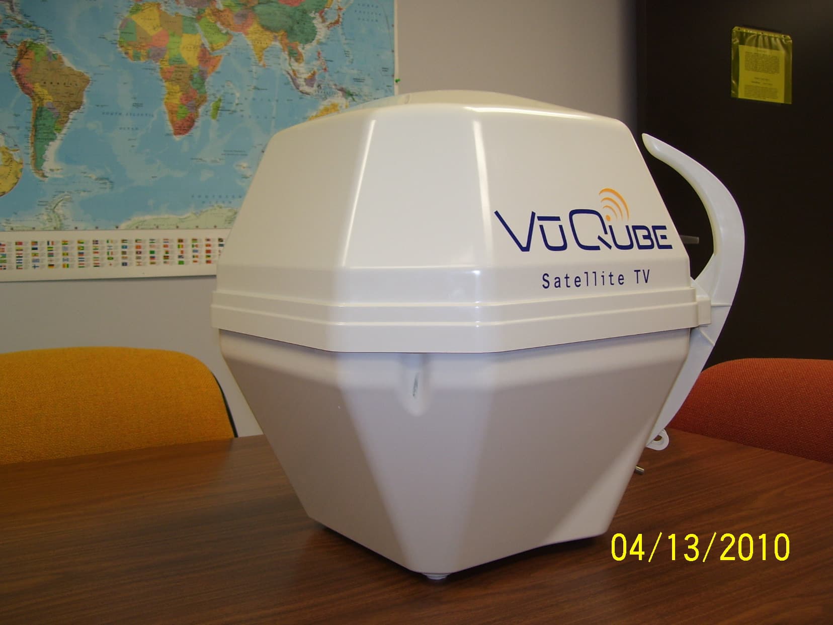
UUM433A
Jun 02, 2010WIRELESS ANTENNA POSITIONING DEVICE
Equipment Class
DSC - Part 15 Security/Remote Control Transmitter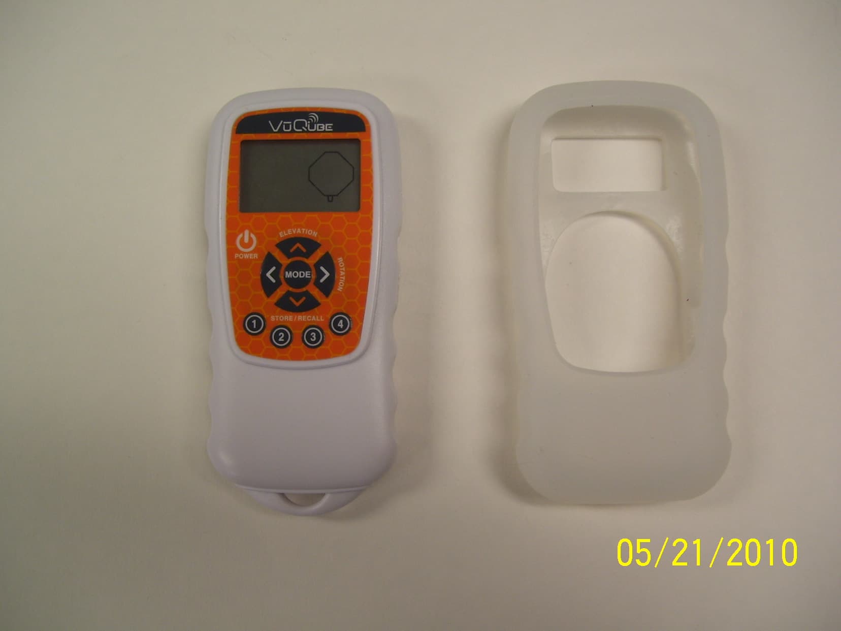
UUM433RA
Jun 02, 2010WIRELESS ANTENNA POSITIONING DEVICE REMOTE CONTROL
Equipment Class
DSC - Part 15 Security/Remote Control Transmitter
UUM10157V10
Jan 28, 2007Vu Qube Remote Control
Equipment Class
DTS - Digital Transmission System