UVZHT1100HT1100 Handy Terminal
ACA Digital Corporation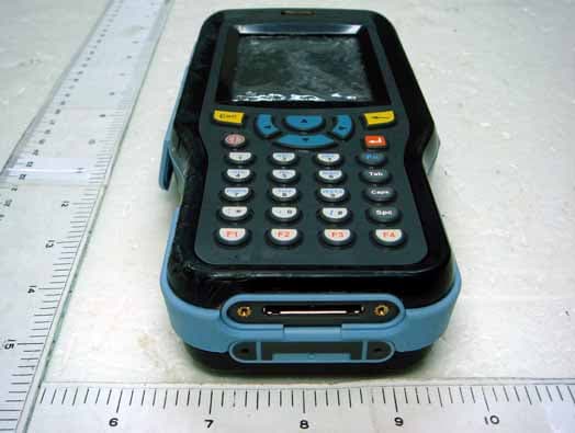
Click to zoom
Application Details
- Equipment Class
- DTS - Digital Transmission System
- Date of Grant
- Jan 09, 2008
- Application Purpose
- Original Equipment
- Date of Application
- Jan 09, 2008
- Equipment Note
- HT1100 Handy Terminal
- Frequency Range
- 2402.00000000 - 2480.00000000
- Company
- ACA Digital Corporation
- Country
- Taiwan
Documents & Files
Document Text
Text extracted from the exhibit documents filed with the FCC. Open a document above to read the original.
Users Manual
Handy Terminal HT1100 User Manual i Preface About This Manual This manual explains how to install, operate and maintain the Handy Terminal HT1100. No part of this publication may be reproduced or used in any form, or by any electrical or mechanical means, without permission in writing from the manufacturer. This includes electronic or mechanical means, such as photocopying, recording, or information storage and retrieval systems. The material in this manual is subject to change without notice. © Copyright 2007 ACA-Digital, Ltd. All rights reserved. Bluetooth is a registered trademark of Bluetooth SIG. Microsoft, Win- dows and ActiveSync are either registered trademarks or trademarks of Microsoft Corporation. Other product names mentioned in this man- ual may be trademarks or registered trademarks of their respective companies and are hereby acknowledged. Preface ii Regulatory Compliance Statements FCC Radiation Exposure Statement This equipment complies with FCC RF radiation exposure limits set forth for an uncontrolled enviroment. This equipment may be held-in-hand in such way that a minimum distance of 20 c m between the handheld device and the user's body is ascertained. The equipment is not approved for body-worn applications. This device complies with Part 15 of the FCC Rules. Operation is subject to the following two conditions: 1) This device may not cause harmful interference, and 2) This device must accept any interference received, including interference that may cause undesired operation. This transmitter must not be co-located or operating in conjunction with any other antenna or transmitter. The equipment with its integral antenna(s) must provide a separation distance of at least 20 cm from all persons and must not be co-located or operating in conjunctions with any other antenna or transmitter. Federal Communications Commission Notice This equipment has been tested and found to comply with the limits for a Class B digital device, pursuant to Part 15 of the FCC Rules. These limits are designed to provide reasonable protection against harmful interference in a residential installation. This equipment generates, uses, and can radiate radio frequency energy. if not installed and used in accordance with the instructions, may cause harmful interference to radio communications. However, there is no guarantee that interference will not occur in a particular installation. If this equipment does cause harmful interference to radio or television reception, which can be determined by turning the equipment off and on, the user encouraged to try and correct the interference by one or more of the following measures: •Reorient or relocate the receiving antenna. •Increase the distance between the equipment and the receiver. •Connect the equipment to an outlet on a circuit different from that to which the receiver is connected. •Consult the dealer or an experienced radio/TV technician for help. To assure continued compliance, any changes or modifications not expressly approved by the party responsible for compliance could void the user's authority to operate this equipment. Preface iii Canada-Industry Canada (IC) The wireless radio of this device complies with RSS 139 & RSS 210 Industry Canada. This Class B digital apparatus complies with Cana- dian ICES-003. Cet appareil numérique de la classe B conforme á la norme NMB-003 du Canada. Europe-European Union Notice Radio products with the CE alert marking comply with the R&TTE Directive (1999/5/EC) issued by the Commission of the European Community. Compliance with this directive implies conformity to the following European Norms (in brackets are the equivalent international standards). •EN 60950-1 (IEC60950-1) - Product Safety •EN 300 328 Technical requirement for radio equipment •ETS 301 489 General EMC requirements for radio equipment. Products that contain the radio transmitter are labeled with CE alert marking and may also carry the CE logo. cUL/UL, TUV, CB, Notice CCC Notice On Class A systems, the following warning will appear near the regula- tory label: WARNING!This is a Class A product. In a domestic environ- ment this product may cause radio interference, in which case the user may be required to take adequate measures. Preface iv Safety Use the following safety guidelines to help protect yourself and the HT1100. CAUTION!Do not operate the HT1100 for an extended period of time with the base resting directly on your body. With extended operation, heat can potentially build up in the base. Allowing sustained contact with the skin could cause discom- fort or, eventually, a burn. •Do not attempt to service the HT1100 yourself. Always follow installation instructions closely. •Be sure that nothing rests on the AC adapter's power cable and that the cable is not located where it can be tripped over or stepped on. •Place the AC adapter in a ventilated area, such as a desktop or on the floor, when you use it to run the HT1100 or to charge the battery. Do not cover the AC adapter with papers or other items that will reduce cooling; also, do not use the AC adapter while it is inside a carrying case. •Use only the AC adapter, power cord, and batteries that are approved for use with this HT1100. Use of another type of bat- tery or AC adapter may cause risk of fire or explosion. •Before you connect the HT1100 to a power source, ensure that the voltage rating of the AC adapter matches that of the available power source. – 115 V/60 Hz in most of North and South America and some Far Eastern countries such as South Korea and Taiwan. – 100 V/50 Hz in eastern Japan and 100 V/60Hz in western Japan. – 230 V/50 Hz in most of Europe, the Middle East, and the Far East. •If you use an extension cable with the AC adapter, ensure that the total ampere rating of the products plugged in to the exten- sion cable does not exceed the ampere rating of the extension cable. •To remove power from the HT1100, turn it off, remove the bat- tery, and disconnect the AC adap…
Text truncated - open the document above for the full version.
Users Manual
Chapter 3 — Using the Hardware 26 Entering Alphanumeric Characters You can use the keypad to enter alphanumeric characters or use the input panel in the operating system. Entering Characters with the Keypad Follow these instructions to enter text with the keypad. •Press the Fn key to toggle keypad input between numeric and alphanumeric input. When the Fn key icon appears in the status tray, input is alphabetic. When the Fn key icon is absent, input is numeric. •To enter letters, press a key to cycle through the letters on the key. For example, pressing will display a lower case ‘a’. •Continue to press to scroll between a, b, and c. Note that if you don’t press the key within two seconds, the cursor will move to the next field. •Press to enter uppercase letters. The Caps icon appears in the system tray. •Press the backspace key to delete characters. •Press the tab key to enter a tab. •Press the enter key to move to a new line. •Press the space key to enter a space. Chapter 3 — Using the Hardware 27 Entering Characters with the Keypad The operating system has a onscreen keyboard that enables you to enter alphanumeric characters with the stylus. Press the input panel icon in the system tray to view the input panel menu. Ta p Keyboard to view the default onscreen keyboard or tap LargeKB to view a large onscreen keyboard. Ta p Hide Input Panel to close the keyboard. The keyboard emulates a standard computer keyboard. Tap the onscreen keyboard to enter, edit, and delete text. Default keyboardLarge keyboard Chapter 3 — Using the Hardware 28 Using the Stylus CAUTION!Never use anything other than the HT1100 stylus on the screen. Using another object as a stylus could cause permanent damage. You can use your finger to interact with the screen as well. 1.Remove the stylus from its holder. 2.Hold the stylus as you would a pencil. 3.To make a choice from a menu, lightly tap the tip of the stylus on that choice. 4.To write data into a field on a form, use the stylus to print the letters or numbers. Use very light pressure. Chapter 3 — Using the Hardware 29 Adjusting the Double-Tap Rate Set the stylus double-tap rate as follows. 1.Tap Start → Settings→ Control Panel. 2.Double-tap Stylus. 3.Tap the Double-Tap tab. 4.Double-tap on the checkerboard graphic to set your double tap rate. Chapter 3 — Using the Hardware 30 Inserting a PCMCIA Card The HT1100 accommodates a Type II PCMCIA card. You can enhance the functionality of the HT1100 by installing PCMCIA cards such as the following: •GPS PC card •GPRS PC card •802.11b/g WLAN PC card •Fingerprint PC card NOTE:The list above are examples of the types of cards you can install and is not exhaustive. Follow these instructions to insert a PCMCIA card into the PCMCIA slot. 1.Remove the screws securing the PCMCIA cover to the chas- sis. 2.Remove the cover. Chapter 3 — Using the Hardware 31 3.Slide the PCMCIA card into the slot as shown, until the con- tacts are seated into the PCMCIA connector. 4.Replace the cover. Chapter 3 — Using the Hardware 32 Removing a PCMCIA Card To remove the PCMCIA card: 1.Press the black PCMCIA button next to the slot The button pops out. 2.Press the button again to push the PCMCIA card out. 3.Remove the card. PCMCIA button Chapter 3 — Using the Hardware 33 Inserting an SD Memory Card Your HT1100 has an expansion slot compatible with a range of SD and MMC storage cards, which are primarily used to back up or transfer files and data. The slot also supports SDIO cards for added connectiv- ity options. Follow these instructions to insert a SD card into the SD slot. 1.Remove the battery compartment cover and battery. See See Installing the Battery on page 12. 2.Insert the SD card with the notched corner as oriented as shown in the following illustration 3.Push the card into the slot. Notched corner Chapter 3 — Using the Hardware 34 The card is secure when it is not protruding from the slot. 4.Replace the cover. Removing a Storage Card 1.Remove the battery compartment cover and battery. See See Installing the Battery on page 12. 2.Press the card in and release. The card pops out. 3.Remove the card from the slot. Chapter 3 — Using the Hardware 35 Connecting Devices to the HT1100 This section describes how to connect devices to the HT1100. You can connect devices directly to the HT1100 or connect using the cradle. Opening the Port Covers The port covers protect the ports and connectors from rain, dust, and adverse environmental conditions. Remove the screws and open the port covers to access the ports. Ensure that you close the covers tightly and replace the screws after disconnecting cables and connectors. Connecting USB The HT1100 accommodates two USB Type A cables. You can connect a USB mini Type B cable to the cradle. See Cradle on page 10. Connecting a USB Type A The illustration dis- played here shows how to connect a USB type A cable to the HT1100. The connector can only go in one way. If it does not go in smoothly, check the orientation and try again. Chapter 3 — Using the Hardware 36 Connecting a USB Type B The illustration dis- played here shows how to connect a mini USB type B cable to the HT1100. The connector is keyed to only go in one way. If it does not go in smoothly, check the orientation and try again. Connecting a Serial Cable Connect a serial cable to the HT1100 to perform serial communica- tions. Refer to the following illustration Chapter 3 — Using the Hardware 37 Connecting Headphones and a Microphone The HT1100 has a built-in microphone and speaker. However, you can connect a headset and microphone to the HT1100 for use in noisy environments. Refer to the following illustrations. Connecting to the Cradle The cradle enables you not only to recharge the HT1100’s batteries, it also enables you to connect USB and serial devices, and connect to the LAN. Connecting USB You can connect both USB Type A and Mini USB Type B connectors to the cradle to transfer data with the HT1100. There is one Mini Type B USB port at the rear …
Text truncated - open the document above for the full version.
Block Diagram
88W8010 On-chip LNA Receiver On-Chip PA VCO Frequency Bytransmitter Transmitter Integrated MAC/BBP Baseband ADC DAC Derroslulator Modulator External Interface Antenna Diversity 88W8385 SPAM Flash Controller Hant Interface DMA Engine GPIO/LED UART Security ARMB CPU Power Mgrrl 802.11 Protocol Engine Internal Bus CSLI ACC/PK_DET ANT_SEL 20/40/44MHz RF File r TR_SW T/R Switch Serial Interf ace, Power Enable Control Flash PC Card, PCI, Mini PCI, Compact Flash SDIO JTAG Serial EEPRCM 3 Wire 4 Wire CPIO Power Enizla Control Serial F Operation Frequency: WLAN (FCC): 2412-2462MHz Bluetooth: 2402-2480MHz
Cover Letter(s)
Request for non-disclosure RF_501_02 ACA Digital Corporation 17F, No. 866-7, Zhongzheng Rd. Zhonghe City, Taipei County 235 Taiwan, R.O.C. To: Telefication B.V. Attn: Dept. FCC TCB Edisonstraat 12A 6902 PK ZEVENAAR The Netherlands Subject: Request for non-disclosure (FCC ID: UVZHT1100) Reference number: HT1100 Date: 2006-11-30 Dear FCC TCB, Persuant to 47 CFR Section 0.459(a) & (b), ACA Digital Corporation hereby requests non-disclosure and confidential treatment of the following materials submitted in support of FCC certification application for FCC ID: ( UVZHT1100) a. Schematic diagrams b. Operational description Above materials contain secrets, proprietary and technical information, which would customarily be quarded from competitors under 47 CFR, section 0.457(d)(2). Disclosure or publication or any portion of this company confidential material to other parties could cause substantial competitive harm and provide unjustified benefits for competitors. ACA Digital Corporation understands that pursuant to 47 CFR section 0.457(d)(1)(ii) disclosure of the applicant and all accompanying documentation will not be made before the date of the grant. Arthur Dai PA Manager ACA Digital Corporation
External Photos
Exclusive Certification Corp. Tel:886-2-2792-3366 Fax:886-2-2792-1100 Issued date: Apr. 24, 2007 1 of 26 FCC Test Report: FI06111401-A Appendix A. Photographs of EUT 06111401-A 06111401-A Exclusive Certification Corp. Tel:886-2-2792-3366 Fax:886-2-2792-1100 Issued date: Apr. 24, 2007 2 of 26 FCC Test Report: FI06111401-A 06111401-A 06111401-A
Internal Photos
Exclusive Certification Corp. Tel:886-2-2792-3366 Fax:886-2-2792-1100 Issued date: Apr. 24, 2007 3 of 26 FCC Test Report: FI06111401-A 06111401-A 06111401-A Exclusive Certification Corp. Tel:886-2-2792-3366 Fax:886-2-2792-1100 Issued date: Apr. 24, 2007 4 of 26 FCC Test Report: FI06111401-A 06111401-A 06111401-A Exclusive Certification Corp. Tel:886-2-2792-3366 Fax:886-2-2792-1100 Issued date: Apr. 24, 2007 5 of 26 FCC Test Report: FI06111401-A 06111401-A 06111401-A Exclusive Certification Corp. Tel:886-2-2792-3366 Fax:886-2-2792-1100 Issued date: Apr. 24, 2007 6 of 26 FCC Test Report: FI06111401-A 06111401-A 06111401-A Exclusive Certification Corp. Tel:886-2-2792-3366 Fax:886-2-2792-1100 Issued date: Apr. 24, 2007 7 of 26 FCC Test Report: FI06111401-A 06111401-A 06111401-A Exclusive Certification Corp. Tel:886-2-2792-3366 Fax:886-2-2792-1100 Issued date: Apr. 24, 2007 8 of 26 FCC Test Report: FI06111401-A 06111401-A 06111401-A Exclusive Certification Corp. Tel:886-2-2792-3366 Fax:886-2-2792-1100 Issued date: Apr. 24, 2007 9 of 26 FCC Test Report: FI06111401-A 06111401-A 06111401-A Exclusive Certification Corp. Tel:886-2-2792-3366 Fax:886-2-2792-1100 Issued date: Apr. 24, 2007 10 of 26 FCC Test Report: FI06111401-A 06111401-A 06111401-A Exclusive Certification Corp. Tel:886-2-2792-3366 Fax:886-2-2792-1100 Issued date: Apr. 24, 2007 11 of 26 FCC Test Report: FI06111401-A 06111401-A 06111401-A Exclusive Certification Corp. Tel:886-2-2792-3366 Fax:886-2-2792-1100 Issued date: Apr. 24, 2007 12 of 26 FCC Test Report: FI06111401-A 06111401-A 06111401-A Exclusive Certification Corp. Tel:886-2-2792-3366 Fax:886-2-2792-1100 Issued date: Apr. 24, 2007 13 of 26 FCC Test Report: FI06111401-A 06111401-A 06111401-A Exclusive Certification Corp. Tel:886-2-2792-3366 Fax:886-2-2792-1100 Issued date: Apr. 24, 2007 14 of 26 FCC Test Report: FI06111401-A 06111401-A Exclusive Certification Corp. Tel:886-2-2792-3366 Fax:886-2-2792-1100 Issued date: Apr. 24, 2007 15 of 26 FCC Test Report: FI06111401-A 06111401-A 06111401-A Exclusive Certification Corp. Tel:886-2-2792-3366 Fax:886-2-2792-1100 Issued date: Apr. 24, 2007 16 of 26 FCC Test Report: FI06111401-A 06111401-A 06111401-A Exclusive Certification Corp. Tel:886-2-2792-3366 Fax:886-2-2792-1100 Issued date: Apr. 24, 2007 17 of 26 FCC Test Report: FI06111401-A 06111401-A 06111401-A Exclusive Certification Corp. Tel:886-2-2792-3366 Fax:886-2-2792-1100 Issued date: Apr. 24, 2007 18 of 26 FCC Test Report: FI06111401-A 06111401-A 06111401-A Exclusive Certification Corp. Tel:886-2-2792-3366 Fax:886-2-2792-1100 Issued date: Apr. 24, 2007 19 of 26 FCC Test Report: FI06111401-A 06111401-A 06111401-A Exclusive Certification Corp. Tel:886-2-2792-3366 Fax:886-2-2792-1100 Issued date: Apr. 24, 2007 20 of 26 FCC Test Report: FI06111401-A 06111401-A 06111401-A Exclusive Certification Corp. Tel:886-2-2792-3366 Fax:886-2-2792-1100 Issued date: Apr. 24, 2007 21 of 26 FCC Test Report: FI06111401-A 06111401-A 06111401-A Exclusive Certification Corp. Tel:886-2-2792-3366 Fax:886-2-2792-1100 Issued date: Apr. 24, 2007 22 of 26 FCC Test Report: FI06111401-A 06111401-A 06111401-A Exclusive Certification Corp. Tel:886-2-2792-3366 Fax:886-2-2792-1100 Issued date: Apr. 24, 2007 23 of 26 FCC Test Report: FI06111401-A 06111401-A Exclusive Certification Corp. Tel:886-2-2792-3366 Fax:886-2-2792-1100 Issued date: Apr. 24, 2007 24 of 26 FCC Test Report: FI06111401-A LE-0309BDSP12V 06111401-A 06111401-A Exclusive Certification Corp. Tel:886-2-2792-3366 Fax:886-2-2792-1100 Issued date: Apr. 24, 2007 25 of 26 FCC Test Report: FI06111401-A 06111401-A 06111401-A Exclusive Certification Corp. Tel:886-2-2792-3366 Fax:886-2-2792-1100 Issued date: Apr. 24, 2007 26 of 26 FCC Test Report: FI06111401-A 06111401-A 06111401-A
RF Exposure Info
1.1. Test Result of RF Exposure Evaluation . Product: HT1100 Handy Terminal . Test Item: RF Exposure Evaluation Data . Test site: OATSI-SD . Test Mode: Normal Operation 1.1.1. Antenna Gain The maximum Gain is 5.5 dBi. 1.1.2. EUT Operation condition Software provided by client enabled the EUT to transmit and receive data at lowest, middle and highest channel individually. 1.1.3. Output Power into Antenna & RF Exposure Evaluation Distance Modulation Standard: IEEE 802.11b Test Date: April. 04, 2007 Temperature: 23 Humidity: 68 Channel Channel Frequency (MHz) Output Power to Antenna (dBm) Power Density (S) (mW/cm 2 ) 01 2412 17.04 0.036 06 2437 17.02 0.036 11 2462 17.41 0.039 Modulation Standard: IEEE 802.11g Test Date: April. 04, 2007 Temperature: 23 Humidity: 68 Channel Channel Frequency (MHz) Output Power to Antenna (dBm) Power Density (S) (mW/cm 2 ) 01 2412 15.74 0.026 06 2437 15.88 0.027 11 2462 15.85 0.027 The MPE is calculated as 0.026 mW / cm 2 < limit 1 mW / cm 2 . So, RF exposure limit warning or SAR test are not required. For 2412-2462 MHz, the EUT will only be used with a separation of 20cm or greater between the antenna and nearby persons and can therefore be considered a mobile transmitter per 47CFR2.1091 (b). The RF Exposure Information page from the manual is included here for reference.
Test Report
Exclusive Certification Corp. Tel:886-2-2792-3366 Fax:886-2-2792-1100 Issued date: Apr. 24, 2007 1 of 56 FCC Test Report: FI06111401-A FCC TEST REPORT according to FCC Rules and Regulations Part 15 Subpart C Applicant : ACA Digital Corporation Address : 17F, No.866-7, ZhongZhen Rd. Zhonghe City, Taipei County, Taiwan, R.O.C Equipment : HT1100 Handy Terminal Model No. : HT1100 FCC ID : UVZHT1100 Trade Name : ACA Digital Laboratory Accreditation 1332 The test result refers exclusively to the test presented test model / sample., Without written approval of Exclusive Certification Corp. the test report shall not be reproduced except in full. The EUT is also considered as a kind of computer peripheral, because the connection to computer is necessary for typical use. It has been verified to comply with the requirements of FCC Part 15, Subpart B, Class B (DoC). The test report has been issued separately. Exclusive Certification Corp. Tel:886-2-2792-3366 Fax:886-2-2792-1100 Issued date: Apr. 24, 2007 2 of 56 FCC Test Report: FI06111401-A Contents 1. Report of Measurements and Examinations .................................................................................... 5 1.1 List of Measurements and Examinations ................................................................................... 5 2. Test Configuration of Equipment under Test ................................................................................... 6 2.1 Feature of Equipment under Test............................................................................................... 6 2.2 RF Specifications ....................................................................................................................... 7 2.3 Test Mode & Test Software ........................................................................................................ 8 2.4 Description of Test System......................................................................................................... 8 2.5 Connection Diagram of Test System.......................................................................................... 9 2.6 General Information of Test......................................................................................................10 2.7 Measurement Uncertainty ........................................................................................................10 2.8 History of this test report .......................................................................................................... 11 3. Antenna Requirements.....................................................................................................................12 3.1 Standard Applicable .................................................................................................................12 3.2 Antenna Construction and Directional Gain............................................................................. 12 4. Test of Conducted Emission............................................................................................................13 4.1 Test Limit.................................................................................................................................. 13 4.2 Test Procedures.......................................................................................................................13 4.3 Typical Test Setup ...................................................................................................................14 4.4 Measurement equipment ......................................................................................................... 14 4.5 Test Result and Data................................................................................................................15 4.6 Test Photographs .....................................................................................................................17 5. Test of Radiated Emission ...............................................................................................................18 5.1 Test Limit.................................................................................................................................. 18 5.2 Test Procedures.......................................................................................................................19 5.3 Typical Test Setup ....................................................................................................................20 5.4 Measurement equipment ......................................................................................................... 20 5.5 Test Result and Data................................................................................................................21 5.6 Test Photographs .....................................................................................................................37 6. 6dB Bandwidth Measurement Data .................................................................................................38 6.1 Test Limit .................................................................................................................................. 38 6.2 Test Procedures .......................................................................................................................38 6.3 Test Setup Layout ....................................................................................................................38 6.4 Measurement equipment ......................................................................................................... 38 6.5 Test Result and Data................................................................................................................38 7. Maximum Peak Output Power .........................................................................................................42 7.1 Test Limit ...............................................................................…
Text truncated - open the document above for the full version.
Test Report
Exclusive Certification Corp. Tel:886-2-2792-3366 Fax:886-2-2792-1100 Issued date: Oct. 31, 2007 1 of 53 FCC Test Report: FI06111401-A(BT) FCC TEST REPORT according to FCC Rules and Regulations Part 15 Subpart C Applicant : ACA Digital Corporation Address : 17F, No.866-7, ZhongZhen Rd. Zhonghe City, Taipei County, Taiwan, R.O.C Equipment : HT1100 Handy Terminal Model No. : HT1100 FCC ID : UVZHT1100 Trade Name : ACA Digital Laboratory Accreditation 1332 The test result refers exclusively to the test presented test model / sample., Without written approval of Exclusive Certification Corp. the test report shall not be reproduced except in full. The EUT is also considered as a kind of computer peripheral, because the connection to computer is necessary for typical use. It has been verified to comply with the requirements of FCC Part 15, Subpart B, Class B (DoC). The test report has been issued separately. Exclusive Certification Corp. Tel:886-2-2792-3366 Fax:886-2-2792-1100 Issued date: Oct. 31, 2007 2 of 53 FCC Test Report: FI06111401-A(BT) Contents 1. Report of Measurements and Examinations .................................................................................... 5 1.1 List of Measurements and Examinations ................................................................................... 5 2. Test Configuration of Equipment under Test ................................................................................... 6 2.1 Feature of Equipment under Test............................................................................................... 6 2.2 RF Specifications ....................................................................................................................... 6 2.3 Test Mode & Test Software ........................................................................................................ 7 2.4 Description of Test System......................................................................................................... 7 2.5 Connection Diagram of Test System.......................................................................................... 8 2.6 General Information of Test........................................................................................................ 9 2.7 Measurement Uncertainty .......................................................................................................... 9 2.8 History of this test report ..........................................................................................................10 3. Antenna Requirements..................................................................................................................... 11 3.1 Standard Applicable ................................................................................................................. 11 3.2 Antenna Construction and Directional Gain............................................................................. 11 4. Test of Conducted Emission............................................................................................................12 4.1 Test Limit.................................................................................................................................. 12 4.2 Test Procedures.......................................................................................................................12 4.3 Typical Test Setup ...................................................................................................................13 4.4 Measurement equipment ......................................................................................................... 13 4.5 Test Result and Data................................................................................................................14 4.6 Test Photographs .....................................................................................................................16 5. Test of Radiated Emission ...............................................................................................................17 5.1 Test Limit.................................................................................................................................. 17 5.2 Test Procedures.......................................................................................................................18 5.3 Typical Test Setup ....................................................................................................................19 5.4 Measurement equipment ......................................................................................................... 19 5.5 Test Result and Data..............................................................…
Text truncated - open the document above for the full version.
Contact Information
Applicant
Ken Lu(Deputy Manager Product Assurance)
Technical Contact
Executive Certification CorporationDelia Feng
[email protected]+886-2-8228-1121
4F-2, No. 28, Lane 78, Xing-ai Rd. · Taipei · Taiwan
Test Firm
Cerpass Technology CorporationAnson Chou
Technical Specifications
| # | Rule Parts | Frequency Range | Power Output |
|---|---|---|---|
| 2 | 15C | 2.40 GHz - 2.48 GHz | 1.30 mW |
Other Applications from ACA Digital Corporation
UVZS10A
Sep 20, 2009Rugged Tablet PC
Equipment Class
DSS - Part 15 Spread Spectrum Transmitter
UVZRF1100
Feb 17, 2008HF RFID Reader
Equipment Class
DXX - Part 15 Low Power Communication Device Transmitter
UVZCT1100
Jul 07, 2007CT1100 Pen Tablet
Equipment Class
DTS - Digital Transmission System
UVZXT1100
May 29, 2007XT1100 Rugged Tablet PC
Equipment Class
DTS - Digital Transmission System