UZ7TW5A2x2 802.11n PCIe MODULE
Zebra Technologies Corporation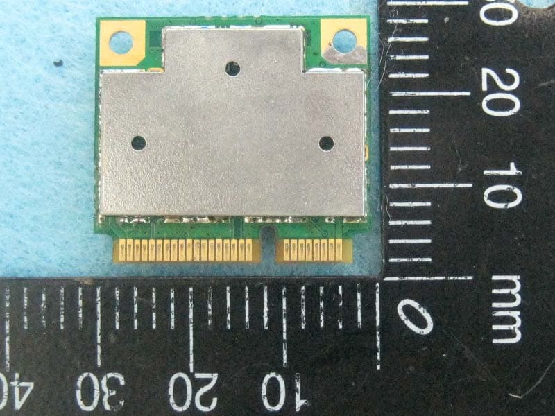
Click to zoom
Application Details
- Equipment Class
- DTS - Digital Transmission System
- Date of Grant
- Jan 14, 2014
- Application Purpose
- Original Equipment
- Date of Application
- Jan 13, 2014
- Equipment Note
- 2x2 802.11n PCIe MODULE
- Frequency Range
- 5755.00000000 - 5795.00000000
- Country
- United States
Documents & Files
Document Text
Text extracted from the exhibit documents filed with the FCC. Open a document above to read the original.
Users Manual
Introduction The Motorola TW-51x Series Wired/Wireless WallPlate is designed for multi-tenant buildings such as hotels, healthcare facilities, apartments, and dormitory housing. The TW-51x is designed to leverage the in-building telephone wiring to deploy Ethernet and wireless LAN networks without the effort and expense of re-wiring with structured cabling. This installation guide applies to TS-524 (P/N TS-0524-WR), TW-511 (P/N TW-0511-60010-US, -EU, -WR), and TW-510 (P/N TW-0510-WR). Document Conventions The following graphical alerts are used in this document to indicate notable situations: NOTETips, hints, or special requirements that you should take note of. CAUTIONCare is required. Disregarding a caution can result in data loss or equipment malfunction. WARNING!Indicates a condition or procedure that could result in personal injury or equipment damage. Warnings • This equipment should only be installed by qualified professional installers. • Read all installation instructions and site survey reports, and verify correct equipment installation before installing this equipment. • Remove jewelry and watches before installing this equipment. • Verify proper wiring and grounding for each installation location . • Verify there is adequate ventilation around the device, and that ambient temperatures meet equipment operation specifications ( 0°to 40°Celsius / 32°to 104°Fahrenheit). TS-524 and TW-5xx Specifications * Operating frequencies and transmit power settings depend on national regulatory limits. Wireless InterfaceSingle radio; 802.11a/b/g/n; 2.4GHz or 5GHz LAN Ethernet port2 x IEEE 802.3 10/100MB auto-sensing via RJ-45 Uplink UTP1 x RJ11 UTP, VDSL2 Pass through phone portFiltered RJ11 port MediumDSSS, OFDM, MIMO Standards802.11a, 802.11b, 802.11g, 802.11n draft 2.0, 802.11i, 802.11-2007 Data rates802.11b: 1,2,5.5, 11Mbps 802.11g: 6, 9, 12,18, 24, 36, 48, 54Mbps 802.11a: 6, 9, 12,18, 24, 36, 48, 54Mbps 802.11n: MCS 0 to 15 up to 300Mbps Operating frequencies*2.4GHz: 2400 to 2483.5MHz 5GHz: 5150 to 5250MHz, 5725 to 5850MHz Transmit power settings*1dBm to 20dBm, in 1dBm increments Antenna configurationTwo internal omni-directional, 1x2 or 2x2 MIMO operation 3dBi peak @ 2.4GHz VLANs802.1 Q tagged VLANS, access or trunk TS-524 managementTelnet, SSH, HTTPS, Serial Console TS-524 uplink ports2 x IEEE 802.3 10/100/1000MB auto-sensing RJ-45 TS-524 UTP ports1 x RJ21 for PBX connection, 1 x RJ21 for downstream VDSL2 MOTOROLA SOLUTIONS INC. 1303 E. ALGONQUIN ROAD SCHAUMBURG, IL 60196 http://www.motorolasolutions.com TS-524 Switch and TW-5xx WallPlate Installation Guide MN000030A01 January 2014 Revision B (2) (1) (3)(4)(5)(6) Installing In-line Filters The TW-5x Wallplate features a built-inPlain Old Telephone Setvice(POTS) and Line Power filter for the desk phone. Install an in-line filter on all other phone jacks that will have a phone connected. The terminated filter has a clipped RJ11 connector. This is purposely done to comply with EN60950 requirements. Use a small flat blade screwdriver to lift the tab if attempting to remove the filter. If installing a filter on a bathroom phone, use the unterminated filter. Remove the bathroom wall plate and terminate the filter in the wall box using wire beans. Installing the TW-51x WallPlate 1. Loosen the screws on the existing wall plate to create a gap of 6mm (1/4 in). 2. Attach the mounting adapter using the keyhole slots. 3. Tighten the screws until the mounting adapter is securely attached. CAUTIONDo not over tighten. 4. Connect the supplied 10cm cable between the TW-51x bottom mounted RJ11 jack and the existing RJ11 jack. 5. Hook the bottom tabs on the mounting adapter to the TW-51x. Rotate and snap the TW-51x onto the adapter. Network Configuration (TS-524) The following will enable all ports and configure one wireless LAN: Log in to the system using Telnet, SSH, HTTP, or Serial Console using the default username and password: Username:admin Password:motorola Enter the following commands: config password admin <enter your new password> country-code <xx =your country> hostname <enter your hostname> interface vlan1 ip-address 192.168.1.1/24 wlan Guest exit int dsl1-24 no shutdown int radio1-24.1 channel 6 power 18 wlan Guest no shutdown exit Enabling Line Power Line power should be enabled after the filters and TW-51x WallPlate have been installed. Line power is safe for use with telephony equipment but it will ring the phones if the filters are not installed first. To enable line power, enter the following commands into the CLI: interface dsl1-24 line-power write memory Regulatory Information This device is approved under Motorola Solutions, Inc. This guide applies to Model Numbers: TS-524, TW-510, and TW-511. All Motorola devices are designed to be compliant with rules and regulations in locations where they are sold and will be labeled as required. Local language translations are available at the following website: http://www.motorolasolutions.com/support. Any changes or modifications to Motorola Solutions equipment, not expressly approved by Motorola Solutions, could void the user's authority to operate the equipment. When Motorola Solutions devices are professionally installed, the Radio Frequency Output Power will not exceed the maximum allowable limit for the country of operation. Antennas: Use only the supplied or an approved replacement antenna. Unauthorized antennas, modifications, or attachments could cause damage and may violate regulations. Radio Modules TheTW-511contains an approved radio module. This module is identified below: Motorola Solutions, Inc. 802.11 a/b/g/n WLAN, Type: TW-5 or TW-5A Wireless Device Country Approvals (TW-511 only) Regulatory markings, subject to certification, are applied to the device signifying the radio(s) is/are approved for use in the following countries: United States, Canada, Japan, China, S. Korea, Australia, and Europe. Please refer to theDeclaration of Conformity(DoC) for details of other country ma…
Text truncated - open the document above for the full version.
Cover Letter(s)
Regulatory Engineering Motorola Solutions, Inc. One Motorola Plaza, | Holtsville, NY 11742 | 1.631.738.2400 phone | 1.631.627.7179 fax | www.motorolasolutions.com December 19, 2013 Federal Communications Commission Office of Engineering and Technology Equipment Authorization Division 7345 Oakland Mills Road Columbia MD 21046 Subject: FCC Attestations, Authorizations, Declarations for FCC ID:UZ7TW5A To the reviewer: I certify that the submitted documents properly describe the radio being submitted. I also certify that each unit manufactured, imported or marketed, as defined in FCC’s regulations will have affixed to it a label with the FCC ID vissable. In addition we acknowledge that all responsibility for complying with the terms and conditions for Certification, still resides with Motorola Solutions, at One Motorola Plaza Holtsville, NY 11742 USA. We have entrusted Leo Huang, of Sporton International Inc., to be our proxy regarding application for this submission. We remain responsible for the contents of the application for FCC ID: UZ7TW5A; submitted by means of this application. In relation to this, we accept all consequences of market surveillance performed by FCC or Technical Certification Body as specified in the FCC’s regulations. In Addition, pursuant to Sections 0.457 and 0.459 of the Commission’s Rules, we request confidential treatment of information accompanying this application for approval as outlined below: 1. Operational Descriptions 2. Schematics 3. Block Diagrams The above materials contains trade secrets and proprietary information not customarily released to the public. Public disclosure of these matters might be harmful to Motorola and provide unjustified benefits Regulatory Engineering Motorola Solutions, Inc. One Motorola Plaza, | Holtsville, NY 11742 | 1.631.738.2400 phone | 1.631.627.7179 fax | www.motorolasolutions.com to our competitors. In Addition, declare that the radio does not support Ad Hoc operation on “non-US and DFS frequencies”. This includes transmissions for beacons, ad-hoc, and peer-to-peer modes. In Addition, declare that the EUT under FCC ID: UZ7TW5A will be installed into a Motorola host, so that we will not supplying an Integrator Manual for third party OEMs. If you have any questions regarding the authorization, please don’t hesitate to contact me. Respectfully, Mark S. Luksich DMTS, Regulatory Engineering 631-738-5134 [email protected]
Cover Letter(s)
Page No. : 23 Module Approval Request Letter Subject: Module Approval Date: 2014/1/10 FCC ID: UZ7TW5A Dear Reviewer, We, Sporton International Inc., are authorized by Motorola Solutions, Inc. to have their state-of-the-art 2x2 802.11n PCIe module approved under module approval authorization. The application of this module is specified to mobile host equipment. The requirements regulated in Public Notice DA00-1407 have been fulfilled and clearly explained below. 1. The requirement of RF shielding: The shielding of the radio portion can be demonstrated in exhibition External Photo. 2. The requirement of buffered inputs: Buffered data inputs stage has been integrated in chip AP9382. 3. The requirement of power supply regulation: The power regulator has been integrated in chip AP9382. 4. The requirements of section 15.203 and 15.204(C): The requirements of antenna connector and spurious emission have been fulfilled. Please reference the exhibition Test Report. 5. The requirement of stand-alone test configuration: Please reference exhibition Test Configuration Photo for the stand-alone test configuration. 6. The requirement of labeling: The instruction on the labeling rule of the end product has been stated in the users manual of this module. Please also see the exhibition Label Sample. 7. The requirement of compliance on specific rule or operating requirements: The required FCC rule has been fulfilled and all the instructions for maintaining compliance has been clearly stated in the Users Manual. 8. The requirement of RF exposure: Please refer exhibition RF Exposure for the compliance of MPE RF exposure rule. Please do not hesitate to contact me for any questions of this request letter. Thank you. Company name : Sporton International Inc. Company Address : No.8, Lane 724, Bo-ai St., Jhubei City, Hsinchu County 302, Taiwan, R.O.C. Signature : Name : Leo Huang Job Title : Manager
Cover Letter(s)
Regulatory Engineering Motorola Solutions, Inc. One Motorola Plaza, | Holtsville, NY 11742 | 1.631.738.2400 phone | 1.631.627.7179 fax | www.motorolasolutions.com December 19, 2013 Federal Communications Commission Office of Engineering and Technology Equipment Authorization Division 7345 Oakland Mills Road Columbia MD 21046 Subject: FCC Attestations, Authorizations, Declarations for FCC ID:UZ7TW5A To the reviewer: I certify that the submitted documents properly describe the radio being submitted. I also certify that each unit manufactured, imported or marketed, as defined in FCC’s regulations will have affixed to it a label with the FCC ID vissable. In addition we acknowledge that all responsibility for complying with the terms and conditions for Certification, still resides with Motorola Solutions, at One Motorola Plaza Holtsville, NY 11742 USA. We have entrusted Leo Huang, of Sporton International Inc., to be our proxy regarding application for this submission. We remain responsible for the contents of the application for FCC ID: UZ7TW5A; submitted by means of this application. In relation to this, we accept all consequences of market surveillance performed by FCC or Technical Certification Body as specified in the FCC’s regulations. In Addition, pursuant to Sections 0.457 and 0.459 of the Commission’s Rules, we request confidential treatment of information accompanying this application for approval as outlined below: 1. Operational Descriptions 2. Schematics 3. Block Diagrams The above materials contains trade secrets and proprietary information not customarily released to the public. Public disclosure of these matters might be harmful to Motorola and provide unjustified benefits Regulatory Engineering Motorola Solutions, Inc. One Motorola Plaza, | Holtsville, NY 11742 | 1.631.738.2400 phone | 1.631.627.7179 fax | www.motorolasolutions.com to our competitors. In Addition, declare that the radio does not support Ad Hoc operation on “non-US and DFS frequencies”. This includes transmissions for beacons, ad-hoc, and peer-to-peer modes. In Addition, declare that the EUT under FCC ID: UZ7TW5A will be installed into a Motorola host, so that we will not supplying an Integrator Manual for third party OEMs. If you have any questions regarding the authorization, please don’t hesitate to contact me. Respectfully, Mark S. Luksich DMTS, Regulatory Engineering 631-738-5134 [email protected]
External Photos
Report No.:290357-08 SPORTON International Inc. PAGE NUMBER : 1 OF 2 TEL : 886-3-327-3456 ISSUED DATE : Jan. 10, 2014 FAX : 886-3-327-0973 Ant.1 Brand: WNC Model Name: 95EAAH15.G07 Gain (dBi): 2.4G: -1.57 5G: 3.71 Photographs of EUT Report No.:290357-08 SPORTON International Inc. PAGE NUMBER : 2 OF 2 TEL : 886-3-327-3456 ISSUED DATE : Jan. 10, 2014 FAX : 886-3-327-0973 Ant.2 Brand: WNC Model Name: 95EAAH15.G08 Gain (dBi): 2.4G: -1.57 5G: 3.71
External Photos
Report No.:290357-08 SPORTON International Inc. PAGE NUMBER : 1 OF 1 TEL : 886-3-327-3456 ISSUED DATE : Jan. 10, 2014 FAX : 886-3-327-0973 Photographs of EUT
Internal Photos
Report No.:290357-08 SPORTON International Inc. PAGE NUMBER : 1 OF 2 TEL : 886-3-327-3456 ISSUED DATE : Jan. 10, 2014 FAX : 886-3-327-0973 Photographs of EUT Report No.:290357-08 SPORTON International Inc. PAGE NUMBER : 2 OF 2 TEL : 886-3-327-3456 ISSUED DATE : Jan. 10, 2014 FAX : 886-3-327-0973
RF Exposure Info
Report No.: FR290357-08 FCC ID: UZ7TW5A Page No. : B1 of B3 Appendix B. Maximum Permissible Exposure Report No.: FR290357-08 FCC ID: UZ7TW5A Page No. : B2 of B3 1. Maximum Permissible Exposure 1.1. Applicable Standard Systems operating under the provisions of this section shall be operated in a manner that ensures that the public is not exposed to radio frequency energy levels in excess limit for maximum permissible exposure. In accordance with 47 CFR FCC Part 2 Subpart J, section 2.1091 this device has been defined as a mobile device whereby a distance of 0.2 m normally can be maintained between the user and the device. (A) Limits for Occupational / Controlled Exposure Frequency Range (MHz) Electric Field Strength (E) (V/m) Magnetic Field Strength (H) (A/m) Power Density (S) (mW/ cm²) Averaging Time |E|²,|H|² or S (minutes) 0.3-3.0 614 1.63 (100)* 6 3.0-30 1842 / f 4.89 / f (900 / f)* 6 30-300 61.4 0.163 1.0 6 300-1500 F/300 6 1500-100,000 5 6 (B) Limits for General Population / Uncontrolled Exposure Frequency Range (MHz) Electric Field Strength (E) (V/m) Magnetic Field Strength (H) (A/m) Power Density (S) (mW/ cm²) Averaging Time |E|²,|H|² or S (minutes) 0.3-1.34 614 1.63 (100)* 30 1.34-30 824/f 2.19/f (180/f)* 30 30-300 27.5 0.073 0.2 30 300-1500 F/1500 30 1500-100,000 1.0 30 Note: f = frequency in MHz ; *Plane-wave equivalent power density 1.2. MPE Calculation Method E (V/m) = d GP30 Power Density: Pd (W/m²) = 377 2 E E = Electric field (V/m) P = Average RF output power (W) G = EUT Antenna numeric gain (numeric) d = Separation distance between radiator and human body (m) The formula can be changed to Pd = 2 377 30 d GP From the EUT RF output power, the minimum mobile separation distance, d=0.2m, as well as the gain of the used antenna, the RF power density can be obtained. Report No.: FR290357-08 FCC ID: UZ7TW5A Page No. : B3 of B3 1.3. Calculated Result and Limit For 5GHz UNII Band: Antenna Type : PIFA Antenna Max Conducted Power for IEEE 802.11n HT40 : 16.96dBm Antenna Gain (dBi) Antenna Gain (numeric) Average Output Power (dBm) Average Output Power (mW) Power Density (S) (mW/cm²) Limit of Power Density (S) (mW/cm²) Test Result 3.71 2.3496 16.9598 49.6569 0.023224 1 Complies For 5GHz ISM Band: Antenna Type : PIFA Antenna Max Conducted Power for IEEE 802.11n HT40 : 23.35 dBm Antenna Gain (dBi) Antenna Gain (numeric) Average Output Power (dBm) Average Output Power (mW) Power Density (S) (mW/cm²) Limit of Power Density (S) (mW/cm²) Test Result 3.71 2.3496 23.3517 216.3562 0.101186 1 Complies For 2.4GHz Band: Antenna Type : PIFA Antenna Max Conducted Power for IEEE 802.11n HT40: 24.54 dBm Antenna Gain (dBi) Antenna Gain (numeric) Average Output Power (dBm) Average Output Power (mW) Power Density (S) (mW/cm²) Limit of Power Density (S) (mW/cm²) Test Result -1.57 0.6966 24.5392 284.3963 0.039434 1 Complies
Test Report
SPORTON International Inc. No. 52, Hwa Ya 1st Rd., Hwa Ya Technology Park, Kwei-Shan Hsiang, Tao Yuan Hsien, Taiwan, R.O.C. Ph: 886-3-327-3456 / FAX: 886-3-327-0973 / www.sporton.com.tw Report Format Version: 01 FCC RADIO TEST REPORT Applicant’s company Motorola Solutions, Inc. Applicant Address One Motorola Plaza Holtsville, NY 11742 USA FCC ID UZ7TW5A Manufacturer’s company Wistron NeWeb Corporation Manufacturer Address 20 Park Avenue II, Hsinchu Science Park, Hsinchu 308,Taiwan,R.O.C. Product Name 2x2 802.11n PCIe module Brand Name MOTOROLA Model No. TW-5A Test Rule Part(s) 47 CFR FCC Part 15 Subpart C § 15.247 Test Freq. Range 2400 ~ 2483.5MHz / 5725 ~ 5850MHz Received Date Nov. 20, 2013 Final Test Date Dec. 26, 2013 Submission Type Original Equipment Statement Test result included is only for the IEEE 802.11n, IEEE 802.11b/g part and IEEE 802.11a (5725 ~ 5850MHz) of the product. The test result in this report refers exclusively to the presented test model / sample. Without written approval of SPORTON International Inc., the test report shall not be reproduced except in full. The measurements and test results shown in this test report were made in accordance with the procedures and found in compliance with the limit given in ANSI C63.10-2009, 47 CFR FCC Part 15 Subpart C, KDB 558074 D01 v03r01 and KDB 662911 D01 v02. The test equipment used to perform the test is calibrated and traceable to NML/ROC. Report No.: FR290357-08AA Report Format Version: 01 Page No. : i of ii FCC ID: UZ7TW5A Issued Date : Jan. 10, 2014 Table of Contents 1. CERTIFICATE OF COMPLIANCE ......................................................................................................................... 1 2. SUMMARY OF THE TEST RESULT .......................................................................................................................... 2 3. GENERAL INFORMATION .................................................................................................................................. 3 3.1. Product Details....................................................................................................................................................................................3 3.2. Accessories .........................................................................................................................................................................................5 3.3. Table for Filed Antenna.......................................................................................................................................................................5 3.4. Table for Carrier Frequencies .............................................................................................................................................................6 3.5. Table for Test Modes ...........................................................................................................................................................................7 3.6. Table for Testing Locations..................................................................................................................................................................9 3.7. Table for Supporting Units ...................................................................................................................................................................9 3.8. Table for Parameters of Test Software Setting ...................................................................................................................................10 3.9. EUT Operation during Test .................................................................................................................................................................10 3.10. Duty Cycle ........................................................................................................................................................................................11 3.11. Test Configurations ...........................................................................................................................................................................15 4. TEST RESULT ................................................................................................................................................... 17 4.1. AC Power Line Conducted Emissions Measurement.........................................................................................................................17 4.2. Maximum Conducted Output Power Measurement .........................................................................................................................21 4.3. Power Spectral Density Measurement ..............................................................................................................................................24 4.4. 6dB Spectrum Bandwidth Measurement ..........................................................................................................................................35 4.5. Radiated Emissions Measurement ....................................................................................................................................................42 4.6. Emissions Measurement ....................................................................................................................................................................69 4.7. Antenna Requirements .....................................................................................................................................................................96 5. LIST OF MEASURING EQUIPMENTS ................................................................................................................... 97 6. MEASUREMENT UNCERTAINTY.......................................................................................................................... 99 APPENDIX A. TEST PHOTOS .......................…
Text truncated - open the document above for the full version.
Test Setup Photos
Report No.: FR290357-08 FCC ID: UZ7TW5A Page No. : A1 of A8 Appendix A. Test Photos Report No.: FR290357-08 FCC ID: UZ7TW5A Page No. : A2 of A8 1. Photographs of Conducted Emissions Test Configuration Test Mode: Mode 1 FRONT VIEW REAR VIEW Report No.: FR290357-08 FCC ID: UZ7TW5A Page No. : A3 of A8 CLOSE VIEW Report No.: FR290357-08 FCC ID: UZ7TW5A Page No. : A4 of A8 2. Photographs of Radiated Emissions Test Configuration Test Configuration: 9kHz ~30MHz Test Mode: Mode 2 FRONT VIEW REAR VIEW Report No.: FR290357-08 FCC ID: UZ7TW5A Page No. : A5 of A8 Test Configuration: 30MHz~1GHz Test Mode: Mode 2 FRONT VIEW REAR VIEW Report No.: FR290357-08 FCC ID: UZ7TW5A Page No. : A6 of A8 CLOSE VIEW Report No.: FR290357-08 FCC ID: UZ7TW5A Page No. : A7 of A8 Test Configuration: Above 1GHz Test Mode: Mode 1 FRONT VIEW REAR VIEW Report No.: FR290357-08 FCC ID: UZ7TW5A Page No. : A8 of A8 CLOSE VIEW
Contact Information
Applicant
Qianlin Zhou(Regulatory Specialist)
Test Firm
Sporton International Inc.Alex Chen
Technical Specifications
| # | Rule Parts | Frequency Range | Power Output |
|---|---|---|---|
| 4 | 15C | 5.75 GHz - 5.79 GHz | 216.00 mW |
Other Applications from Zebra Technologies Corporation
UZ7DS8288R
Jun 29, 2026Cordless Scanner
Equipment Class
DTS - Digital Transmission SystemUZ7DS8208R
Jun 29, 2026Cordless Scanner
Equipment Class
DSS - Part 15 Spread Spectrum TransmitterUZ7TCW01G
Jun 23, 2026Touch Computer
Equipment Class
CBE - Citizens Band End User DevicesUZ7TCW010
May 29, 2026Touch Computer
Equipment Class
NII - Unlicensed National Information Infrastructure TXUZ7TC101B
Apr 29, 2026Touch Computer
Equipment Class
DSS - Part 15 Spread Spectrum Transmitter