UZ7VC6096Vehicle and Fixed Office Data Terminal
Zebra Technologies Corporation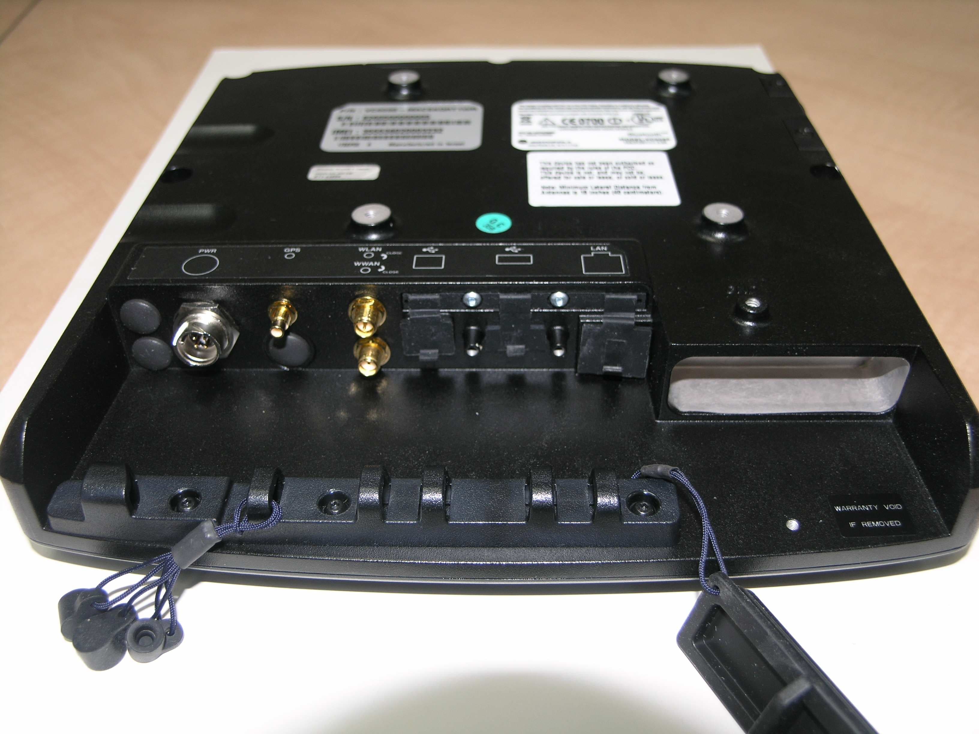
Click to zoom
Application Details
- Equipment Class
- JBP - Part 15 Class B Computing Device Peripheral
- Date of Grant
- Dec 09, 2008
- Application Purpose
- Original Equipment
- Date of Application
- Dec 09, 2008
- Equipment Note
- Vehicle and Fixed Office Data Terminal
- Country
- United States
Documents & Files
Document Text
Text extracted from the exhibit documents filed with the FCC. Open a document above to read the original.
Users Manual
VC6000 Series Quick Reference Guide Draft - October 16, 2008 © 2008 MOTOROLA, INC. All rights reserved. Motorola reserves the right to make changes to any product to improve reliability, function, or design. Motorola does not assume any product liability arising out of, or in connection with, the application or use of any product, circuit, or application described herein. No license is granted, either expressly or by implication, estoppel, or otherwise under any patent right or patent, covering or relating to any combination, system, apparatus, machine, material, method, or process in which Motorola products might be used. An implied license exists only for equipment, circuits, and subsystems contained in Motorola products. MOTOROLA, and the Stylized M Logo are registered in the US Patent & Trademark Office. Other product names mentioned in this manual may be trademarks or registered trademarks of their respective companies and are hereby acknowledged. Motorola, Inc. One Motorola Plaza Holtsville, N.Y. 11742-1300, USA www.motorola.com/enterprisemobility Warranty Subject to the terms of Motorola’s hardware warranty statement, the VC6000 series products are warranted against defects in workmanship and materials for a period of one year from the date of shipment. For the complete Motorola hardware product warranty statement, go to: www.motorola.com/enterprisemobility/warranty. Patents This product is covered by one or more patents. For patent information go to: www.motorola.com/enterprisemobility/patents. Quick Reference Guide1 Introduction The Motorola VC6000 series is a rugged vehicle or fixed-mount computer. It is specifically designed for the harsh conditions of the mobile environment areas. The VC6000 also serves as a stationary indoor host computer for communication and control of outdoor VC6000 seriess. The computer enables real-time data access, collection, capture and report of information related to the driver’s workflow, status and location. The fixed-mount computer consists of a touch-screen with an integrated QWERTY keyboard. Data can be entered using the touch-screen or keyboard. The computer has multiple communication capabilities that include: Wireless Local Area Network (WLAN), Wireless Wide Area Network (WWAN), Bluetooth TM and a Global Positioning System (GPS) receiver. Bluetooth technology is used for cordless connection of peripheral devices such as printers, bar code scanners, handsfree speakers and headsets to the computer. Cellular and WiFi radios are used to exchange voice and data with wide and local area networks. Among its many communication interfaces, the computer contains an internal GPS module, ensuring reliable and accurate vehicle location. The VC6000 Vehicle Computer series is designed only for industry and commercial use. In indoor applications, the VC6000 can serve as a fixed- mount office computer for communication and data collection. The VC6000 is not designed to operate as portable lap-top computer. The computer, antenna(s) and other accessories of the VC6000 require a professional installation performed by trained and licensed personnel. For proper installation requirements, contact your professional installer, VAR, or antenna manufacturer. 2VC6000 Series Vehicle Computers Model Configurations This guide covers the configuration of the following VC6000 series models: The vehicle computer features: • Ergonomic design with a color LCD touch screen • Windows Mobile 6.1 operating system • Internal Bluetooth radio to enable wireless connection to a Bluetooth printer, bar code scanner, headset and other Bluetooth peripherals. • Connection to WLAN in 802.11a/b/g standards (VC6096 only) • Connection to WWAN using a Global System for Mobile communica- tion (GSM) cellular radio and High-Speed Downlink Packet Access (HSDPA) (VC6096 only) • 10/100 Ethernet port for connection to Local Area Network (LAN) • Vehicle motion and location detection via the vehicle telemetry and the GPS receiver (VC6096 only) • Serial RS232 interface • Full speed USB ports • Wide-range of input power (10 V DC to 33 V DC) to accommodate a wide range of vehicles • Reliable operation in cold environments, as low as -20 °C (- 4 °F) • Maximum operational temperature 60 °C (140 °F) Configuration Model VC6000VC6096 Operating SystemWindows Mobile 6.1 Classic Windows Mobile 6.1 Professional GPSNoYes Bluetooth Ye sYe s Wireless LANNoYes (802.11 a/b/g) Cellular radio (HSDPA, UMTS, GSM, GPRS, EDGE) NoYes (Voice and data) Vehicle TelemetryNoYes Quick Reference Guide3 Features Front Features 1 See “System Indication LED” on page 17. 2 For LED indications, refer to your enterprise application manual. 3 For key function, refer to the text displayed on the screen. 4 For operation, refer to your enterprise application guide. 1. Reset Button with system indication LED 1 2. Two green LEDs driven by application 2 3. Volume up/down key (6 levels) 4. Brightness up/down key 5. Microphone (embedded) 6. Full QWERTY keypad 7. Left soft key 3 8. Right soft key 3 9. Home key 10. Back key 11. Navigation key 12. Select key 13. Speaker (embedded) 14. Function keys 4 15. Touch screen 2 4 8 9 6 7 3 11 12 13 5 10 14 15 1 4VC6000 Series Vehicle Computers Back Features 1 Rotate counterclockwise to fasten connector. 2 Keep covered when not in use. 3 Includes: 8 digital inputs, 8 digital outputs, 2 analog inputs, 2 pins for de- bugging, 2 full RS232, CAN2.0 - J1939 (Telemetry), J1708 (Telemetry). 1. PWR - Power connector 2. GPS antenna connector 3. WWAN antenna connector 4. WLAN antenna connector 1 5. Mini USB port, type B 2 6. USB port, type A 2 7. 10/100 Ethernet port 2 8. Auxiliary port 2, 3 9. SIM card slot 2 10. SD memory card slot 2 11. USB port, type A 2 12. M4 screw mounting bosses 13. M4 Ground screw boss 6 8 7 1 12 13 43 10 9 11 52 Quick Reference Guide5 Unpacking The following items are contained inside the shipping box: • VC6000 series • Hardware Kit (including five M4 installation screws) •This guide Optional …
Text truncated - open the document above for the full version.
Cover Letter(s)
Motorola, Inc. • One Motorola Plaza, Holtsville, NY 11742-1300 • 1.631.738.5134 24 September 2008 Regulatory Engineering PHOENIX TESTLAB GmbH Product Certification Königswinkel 10 D 32825 Blomberg To Whom It May Concern: Please be advised that Motorola authorizes Oliver Wagener, of 7 layers AG to act on our behalf, until otherwise notified, for applications submitted to PHOENIX TESTLAB GmbH (PTL). Thank you for your attention to this matter. Respectfully, Mark S. Luksich DMTS, Regulatory Engineering 631-738-5134 Mark [email protected]
Cover Letter(s)
Motorola, Inc. • One Motorola Plaza, Holtsville, NY 11742-1300 • 1.631.738.5134 September 17, 2008 Regulatory Engineering Federal Communications Commission Office of Engineering and Technology Equipment Authorization Division 7345 Oakland Mills Road Columbia MD 21046 Subject: Request for Short-Term Confidentiality for information pertaining to FCC ID:UZ7VC6096 To the Commission: Pursuant to DA 04-1705 of the Commission’s public notice, we request that the exhibits identified below for FCC ID:UZ7VC6096, be covered by Short Term Confidentiality for a period of 45 days after the Grant Date of Equipment Authorization. This is to ensure sensitive business information remains confidential until the actual marketing of the device. EXHIBIT (1) User Manual EXHIBIT (6) Internal Pictures EXHIBIT (7) External Photographs EXHIBIT (8) Test Setup Photographs If you have any questions regarding this request, please don’t hesitate to contact me. Respectfully, Mark S. Luksich DMTS, Regulatory Engineering 631-738-5134 [email protected]
External Photos
Applicant: Motorola Inc. FCC ID: UZ7VC6096 Exhibit 3 Page 1 of 8 EXTERNAL PHOTOGRAPHS This document contains 7 photographs Applicant: Motorola Inc. FCC ID: UZ7VC6096 Exhibit 3 Page 2 of 8 Photo. No.1 VC6096 - Front View Applicant: Motorola Inc. FCC ID: UZ7VC6096 Exhibit 3 Page 3 of 8 Photo. No.2 VC6096 - Rear View along with FCC Label Applicant: Motorola Inc. FCC ID: UZ7VC6096 Exhibit 3 Page 4 of 8 Photo. No.3 VC6096 - Rear View Applicant: Motorola Inc. FCC ID: UZ7VC6096 Exhibit 3 Page 5 of 8 Photo. No.4 VC6096 – Left Side View Applicant: Motorola Inc. FCC ID: UZ7VC6096 Exhibit 3 Page 6 of 8 Photo. No.5 VC6096 – Right Side View Applicant: Motorola Inc. FCC ID: UZ7VC6096 Exhibit 3 Page 7 of 8 Photo. No.6 VC6096 – Top Side View Applicant: Motorola Inc. FCC ID: UZ7VC6096 Exhibit 3 Page 8 of 8 Photo. No.7 VC6096 with Antenna and PS. Combo Antenna Power Supply
ID Label/Location Info
Applicant: Motorola Inc. FCC ID: UZ7VC6096 Exhibit 1 FCC IDENTIFICATION LABEL and LOCATION Required Under Section: 47 CFR 2.1033(b)(7), 2.1033(c) 11 FCC ID: UZ7VC6096 Identifier label for the models: (VC6096) Label Location: Back side of the VC6096 Applicant: Motorola Inc. FCC ID: UZ7VC6096 Exhibit 1 General Information --- 47 CFR 2.1031. 1A.1. Production Plans -- Pursuant 47 CFR 2.1031 Quantity production is planned. 1A.2. Application References: Pursuant to 47 CFR 2.948 and 2.1061 Reference is made to the following Motorola "Application References" 1A.4. Data Submittal Procedure Data located in Exhibit 6 is supplied in accordance with Part 2, Subpart J and Part 15, subpart C of the Commissions’ rules and will be submitted electronically. 1A.5. Application References: Pursuant to 47 CFR 2.948 and 2.1061
Internal Photos
Applicant: Motorola Inc. FCC ID:UZ7VC6096 Exhibit 9 Page 1 of 16 INTERNAL PHOTOGRAPHS This document contains 15 photos Applicant: Motorola Inc. FCC ID:UZ7VC6096 Exhibit 9 Page 2 of 16 Photo. No.1 Internal view. Applicant: Motorola Inc. FCC ID:UZ7VC6096 Exhibit 9 Page 3 of 16 Photo No. 2 WLAN Radio Applicant: Motorola Inc. FCC ID:UZ7VC6096 Exhibit 9 Page 4 of 16 Photo No. 3 Main Board bottom side with shields HC25 WWAN module Applicant: Motorola Inc. FCC ID:UZ7VC6096 Exhibit 9 Page 5 of 16 Photo No. 4 BT components under shield BT Antenna Applicant: Motorola Inc. FCC ID:UZ7VC6096 Exhibit 9 Page 6 of 16 Photo No. 5 BT Radio with no shield Applicant: Motorola Inc. FCC ID:UZ7VC6096 Exhibit 9 Page 7 of 16 Photo. No.6 Main Board Applicant: Motorola Inc. FCC ID:UZ7VC6096 Exhibit 9 Page 8 of 16 Photo No. 7 VC6096 Main Board bottom side w/o shields
Internal Photos
Applicant: Motorola Inc. FCC ID:UZ7VC6096 Exhibit 9 Page 9 of 16 Photo No. 8 VC6096 Main Board bottom side w/o shields and w/o WWAN module Applicant: Motorola Inc. FCC ID:UZ7VC6096 Exhibit 9 Page 10 of 16 Photo No. 9 VC6096 Main Board top side with shields Applicant: Motorola Inc. FCC ID:UZ7VC6096 Exhibit 9 Page 11 of 16 Photo No. 10 VC6096 Main Board top side w/o shields Applicant: Motorola Inc. FCC ID:UZ7VC6096 Exhibit 9 Page 12 of 16 Photo No. 11 Inverter Board Bottom Applicant: Motorola Inc. FCC ID:UZ7VC6096 Exhibit 9 Page 13 of 16 Photo No. 12 Inverter Board Top Applicant: Motorola Inc. FCC ID:UZ7VC6096 Exhibit 9 Page 14 of 16 Photo No. 13 Keypad Board bottom side w/o Shields Applicant: Motorola Inc. FCC ID:UZ7VC6096 Exhibit 9 Page 15 of 16 Photo No. 14 Keypad Board bottom side with Shields Applicant: Motorola Inc. FCC ID:UZ7VC6096 Exhibit 9 Page 16 of 16 Photo No. 15 Keypad Board Top side
Test Setup Photos
Annex III: Test Setup Photos Date: 2008-09-30 Annex III: Test Setup Photos Page 2 of 3 1 Photo Report Photo 1: Test setup for radiated measurements (up to 30 MHz) Photo 2: Setup for radiated tests below 1 GHz Annex III: Test Setup Photos Page 3 of 3 Photo 3: Setup for radiated tests above 1 GHz Photo 4: Setup for conducted tests
Contact Information
Applicant
Qianlin Zhou(Regulatory Specialist)
Test Firm
7layers AGRobert Machulec
Technical Specifications
| # | Rule Parts | Frequency Range | Power Output |
|---|---|---|---|
| 1 | 15B | - | - |
Other Applications from Zebra Technologies Corporation
UZ7DS8288R
Jun 29, 2026Cordless Scanner
Equipment Class
DTS - Digital Transmission SystemUZ7DS8208R
Jun 29, 2026Cordless Scanner
Equipment Class
DSS - Part 15 Spread Spectrum TransmitterUZ7TCW01G
Jun 23, 2026Touch Computer
Equipment Class
CBE - Citizens Band End User DevicesUZ7TCW010
May 29, 2026Touch Computer
Equipment Class
NII - Unlicensed National Information Infrastructure TXUZ7TC101B
Apr 29, 2026Touch Computer
Equipment Class
DSS - Part 15 Spread Spectrum Transmitter