V3J-JBDJAWBONE (BLUETOOTH VOIP DONGLE)
Aliph com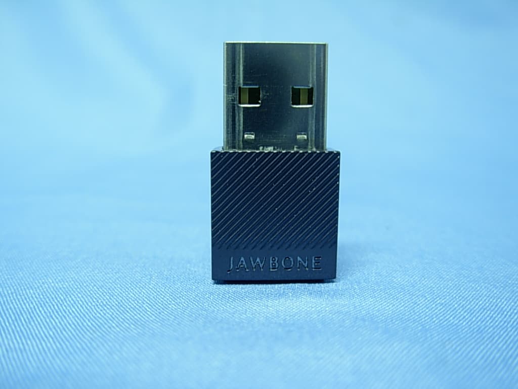
Click to zoom
Application Details
- Equipment Class
- DSS - Part 15 Spread Spectrum Transmitter
- Date of Grant
- May 16, 2011
- Application Purpose
- Original Equipment
- Date of Application
- May 16, 2011
- Equipment Note
- JAWBONE (BLUETOOTH VOIP DONGLE)
- Frequency Range
- 2402.00000000 - 2480.00000000
- Company
- Aliph com
- Country
- United States
Documents & Files
Document Text
Text extracted from the exhibit documents filed with the FCC. Open a document above to read the original.
Users Manual
USER GUIDE JBD CONTENTS JBD ANATOMY GET CONNECTED GET TALKING & MORE SAFETY INFORMATION WATCH TUTORIAL VIDEOS AT JAWBONE.COM/ICON/VIDEOS JBD ANATOMY IF THE LED IS . . . QUICKLY FLASHING The JBD is trying to pair with your Jawbone. SLOWLY FLASHING The JBD is paired with your Jawbone and ready for use. GET CONNECTED 1 . 1 PREPARE YOUR JAWBONE 1 Press & hold the TALK BUTTON 2 Slide the POWER SWITCH on 3 Wait for the LED RING to fl ash red & white 4 Release the TALK BUTTON 1 . 2 CONNECT WITH YOUR COMPUTER 1 Prepare your Jawbone. See 1 .1 2 Plug Jawbone JBD into your computer 3 Press and hold the CONNECT button 4 Wait for the LED RING on your Jawbone ICON to display white and then disappear 5 Release the CONNECT button 1 . 3 CONNECT WITH YOUR PHONE 1 Prepare your Jawbone. See 1 .1 2 Turn on Bluetooth® ON AN IPHONE® Go to SETTINGS > GENERAL > and enable BLUETOOTH 8 ON A BLACKBERRY® Go to SETTINGS/OPTIONS > BLUETOOTH and enable BLUETOOTH OTHER CELL PHONES Go to JAWBONE.COM/PAIRING or review the instruction manual that came with your phone. 3 Go to your phone’s Bluetooth® settings. ADD OR SEARCH FOR DEVICES When “Jawbone ICON” appears, select it. IF ASKED FOR A PASSCODE Enter “0000” This is a one-time event per phone. To pair your Jawbone headset to another phone, repeat steps 1.1 to 1.3. GET TALKING & MORE 2 . 1 MAKE A CALL Use your computer to dial via Skype®, Google Talk (SM), and others. Listen and talk through your Jawbone ICON. 2 . 2 STREAM AUDIO Use your phone or computer to dial as usual. Listen and talk through your Jawbone. 2 . 3 ADJUST THE VOLUME Use the volume control on your phone or computer. Or, while on a call or listening to music, PRESS + HOLD the TALK BUTTON and the volume level will cycle up and down. When you find the most comfortable volume level, release the button and your volume will be set. 2 . 4 SWITCH BETWEEN AUDIO & CALLS (OR SIMULTANEOUS MULTIPOINT) Listen and talk on your computer while staying connected to your mobile phone. The audio from your computer will fade away when you answer or make a call on your mobile phone and resume when you hang up. SAFETY INFORMATION WARNING Failure to follow these safety instructions could result in hearing damage or in fire, electric shock, or other injury or damage. Avoiding Hearing Damage Permanent hearing loss may occur if the Jawbone® headset is used at a high volume. Set the volume to a safe level. Even though you may become accustomed to a higher volume of sound, and even though it may sound normal, any higher volume of sound can be damaging to your hearing. If you experience ringing in your ears or muffled speech, stop listening and have your hearing checked. The louder the volume, the less time is required before your hearing could be affected. The Jawbone® headset has been initially set at a medium volume for sound. Do not increase the level of volume unless you are in conditions where you need a higher level for a short period of time. If this level of volume is uncomfortably high for you, you should decrease this level. hearing e x perts suggest that to protect your hearing : 1 Limit the amount of time you use the Jawbone® headset including use at high volume. 2 Avoid turning up the volume to block out noisy surroundings. 3 Turn the volume down if you can’t hear people speaking near you. 12 Jawbone Headset Care • Do not expose your Jawbone® headset to liquid, moisture, humidity, or rain. The Jawbone® headset is not waterproof. • Do not tamper with or abuse the Jawbone® headset. For example, without limitation, do not drop, disassemble, open, crush, bend, deform, puncture, shred, microwave, incinerate, paint, or insert foreign objects into the Jawbone® headset. • Do not use abrasive cleaners to clean your Jawbone® headset. • Do not expose your Jawbone® headset to extremely high or low temperatures. • Do not leave your Jawbone® headset in direct sunlight for an extended period of time. • Do not leave your Jawbone® headset near open flames such as cooking burners. • Do not dispose of your Jawbone® headset in a fire. The battery could explode. • Do not bring your Jawbone® headset into contact with any sharp objects. This can cause scratches and damage. • Do not insert anything into your Jawbone® headset unless otherwise specified in the user manual. This may damage the internal components. • Do not attempt to disassemble your Jawbone® headset, it does not contain serviceable components. • Do not wear your Jawbone headset without an AliphCom approved earbud. Built-in Battery Care • Do not attempt to replace your Jawbone® headset’s battery. It is built-in and not changeable. • Charge the battery in accordance with the instructions supplied with this guide. • Use only the charger supplied by Jawbone® headset’s original manufacturer to charge the battery. 13 Charger Care • Use only the charger supplied by the Jawbone® headset’s original manufacturer to charge your Jawbone® headset. Other chargers may look similar but using them could be dangerous and could damage the Jawbone® headset. • Do not attempt to disassemble the charger as it may expose you to dangerous electric shock. • Do not use the charger outdoors or in damp areas. • Only charge your Jawbone® headset’s built-in battery in accordance with the instructions described in this guide. • Avoid charging your Jawbone® headset in extremely high or low temperatures. • Do not use your Jawbone® headset while it is charging. • Do not connect the Jawbone® headset to the charger while on an active call. Safety Information • Check and observe local laws regarding the use of a mobile phone and headset while driving. If you use the Jawbone® headset while driving, ensure that you maintain your full attention and focus; it is your responsibility to drive safely. Consider pulling off the road before making or answering a call. • Never allow children to play with the Jawbone® headset; the small components of the headset may be a choking hazard. • Do not leave or store the Jawbone® heads…
Text truncated - open the document above for the full version.
External Photos
Report No:10A103R-RFUSP43V01 Page: 82 of 85 Attachement EUT Photograph (1) EUT Photo (2) EUT Photo
Internal Photos
Report No:10A103R-RFUSP43V01 Page: 83 of 85 (3) EUT Photo (4) EUT Photo Report No:10A103R-RFUSP43V01 Page: 84 of 85 (5) EUT Photo (6) EUT Photo Report No:10A103R-RFUSP43V01 Page: 85 of 85 (7) EUT Photo
RF Exposure Info
Report No. 10A103R-RF-US-Exp Page: 1 of 3 RF Exposure Evaluation declaration Product Name :Jawbone Model No. :JBD FCC ID. :V3J-JBD Applicant : Aliph com Address : 99 Rhode Island Street 3rd Floor, San Francisco, 94103 Date of Receipt : 2010/10/04 Date of Declaration : 2010/10/07 Report No. : 10A103R-RF-US-Exp Report Version : V1.0 The declaration results relate only to the samples calculated. The declaration shall not be reproduced except in full without the written approval of QuieTek Corporation. Report No. 10A103R-RF-US-Exp Page: 2 of 3 1. RF Exposure Evaluation 1.1. Limits According to 1.1307(b)(1), system operating under the previsions of this section shall be operated in manner that ensure that the public is not exposed is not exposed to radio frequency energy level in excess of the Commission’s guideline. No Evaluation required for output power as below thresholds: f = GHz, d = Distance (between radiated device and the body) When d < 2.5cm, Output Power = (60/f) mW Ex: f = 2.4GHz, Output Power = (60/2.4) = 25mW (13.98dBm) When d≧2.5cm, and < 20cm, Output Power = (120/f) mW Ex: f = 2.4GHz, Output Power = (120/2.4) = 50mW (16.99 dBm) 1.2. Test Procedure Software provided by client enabled the EUT to transmit and receive data at lowest, middle and highest channel individually. The temperature and related humidity: 18°Cand 78% RH. Report No. 10A103R-RF-US-Exp Page: 3 of 3 1.3. Test Result of RF Exposure Evaluation Product Jawbone Test Mode Mode 1: Transmit Test Condition RF Exposure Evaluation Antenna Gain Antenna Gain: The maximum Gain measured in fully anechoic chamber is -7.42dBi or 0.181 in linear scale. Output Power into Antenna Channel Channel Frequency (MHz) Output Power to Antenna (mW) Output Power threshold (mW) (d < 2.5cm) 00 2402.00 0.454 24.979 39 2441.00 0.403 24.580 78 2480.00 0.429 24.194 Conclusion: No SAR evaluation required, since transmitter output power is below threshold.
Test Report
Report No:10A103R-RFUSP43V01 Page: 1 of 85 Test Report Product Name:Jawbone Model No. :JBD FCC ID. :V3J-JBD Applicant : Aliph com Address : 99 Rhode Island Street 3rd Floor, San Francisco, 94103 Date of Receipt:2010/10/04 Issued Date :2010/10/07 Report No. :10A103R-RFUSP43V01 Report Version :V1.0 The test results relate only to the samples tested. The test report shall not be reproduced except in full without the written approval of QuieTek Corporation. Report No:10A103R-RFUSP43V01 Page: 2 of 85 Test Report Certification Issued Date : 2010/10/07 Report No. : 10A103R-RFUSP43V01 Product Name : Jawbone Applicant : Aliph com Address : 99 Rhode Island Street 3rd Floor, San Francisco, 94103 Manufacturer : Fu Gang (Dong Guan) Electronic Co., LTD. Model No. : JBD FCC ID. : V3J-JBD EUT Voltage : DC 5V Trade Name : JAWBONE Applicable Standard : FCC CFR Title 47 Part 15 Subpart C Section 15.247: 2009 Test Result : Complied The test results relate only to the samples tested. The test report shall not be reproduced except in full without the written approval of QuieTek Corporation. Documented By : ( Demi Chang / Engineering Adm. Specialist ) Reviewed By : ( Sheena Huang / Engineer ) Approved By : ( Roy Wang / Manager ) Report No:10A103R-RFUSP43V01 Page: 3 of 85 TABLE OF CONTENTS Description Page 1. General Information........................................................................................................ 5 1.1. EUT Description..........................................................................................................................5 1.2. Operational Description.............................................................................................................7 1.3. Test Mode....................................................................................................................................8 1.4. Tested System Details................................................................................................................9 1.5. Configuration of tested System..............................................................................................10 1.6. EUT Exercise Software............................................................................................................10 1.7. Test Facility................................................................................................................................11 2. Conducted Emission .................................................................................................... 13 2.1. Test Equipment.........................................................................................................................13 2.2. Test Setup..................................................................................................................................13 2.3. Limits...........................................................................................................................................14 2.4. Test Procedure..........................................................................................................................14 2.5. Test Specification......................................................................................................................14 2.6. Uncertainty.................................................................................................................................14 2.7. Test Result.................................................................................................................................15 2.8. Test Photo..................................................................................................................................17 3. Peak Power Output ...................................................................................................... 18 3.1. Test Equipment.........................................................................................................................18 3.2. Test Setup..................................................................................................................................18 3.3. Test procedures.........................................................................................................................18 3.4. Limits...........................................................................................................................................18 3.5. Test Specification......................................................................................................................18 3.6. Test Result.................................................................................................................................19 4. Radiated Emission ....................................................................................................... 28 4.1. Test Equipment.........................................................................................................................28 4.2. Test Setup..................................................................................................................................28 4.3. Limits...........................................................................................................................................29 4.4. Test Procedure..........................................................................................................................29 4.5. Test Specification......................................................................................................................29 4.6. Test Result.................................................................................................................................30 4.7. Test Photo..................................................................................................................................38 5. RF antenna conducted test ....................................................................................…
Text truncated - open the document above for the full version.
Test Setup Photos
Report No:10A103R-RFUSP43V01 Page: 17 of 85 2.8. Test Photo Test Mode : Mode 1: Transmit Description: Front View of Conducted Emission Test Setup Test Mode : Mode 1: Transmit Description: Back View of Conducted Emission Test Setup Report No:10A103R-RFUSP43V01 Page: 38 of 85 4.7. Test Photo Test Mode : Mode 1: Transmit Description: Front View of Radiated Emission Test Setup (Bilog) Test Mode : Mode 1: Transmit Description: Back View of Radiated Emission Test Setup (Bilog) Report No:10A103R-RFUSP43V01 Page: 39 of 85 Test Mode : Mode 1: Transmit Description: Front View of Radiated Emission Test Setup (Horn) Test Mode : Mode 1: Transmit Description: Back View of Radiated Emission Test Setup (Horn)
Contact Information
Applicant
Dileep Goyal(Director of System and Material)
Test Firm
QuieTek CorporationWarren Lin
Technical Specifications
| # | Rule Parts | Frequency Range | Power Output |
|---|---|---|---|
| 1 | 15C | 2.40 GHz - 2.48 GHz | 1.00 mW |
Other Applications from Aliph com
V3J-JL03
Dec 18, 2014Band
Equipment Class
DTS - Digital Transmission System
V3J-JL04
Oct 26, 2014Band
Equipment Class
DTS - Digital Transmission System
V3J-JL06
Oct 06, 2014Bluetooth device
Equipment Class
DTS - Digital Transmission System
V3J-JC01
Nov 06, 2013Headset
Equipment Class
DSS - Part 15 Spread Spectrum Transmitter
V3J-J2013
Jul 07, 2013J2013
Equipment Class
DTS - Digital Transmission System