V4TJR2TX1RadioPopper
Leap Devices, LLC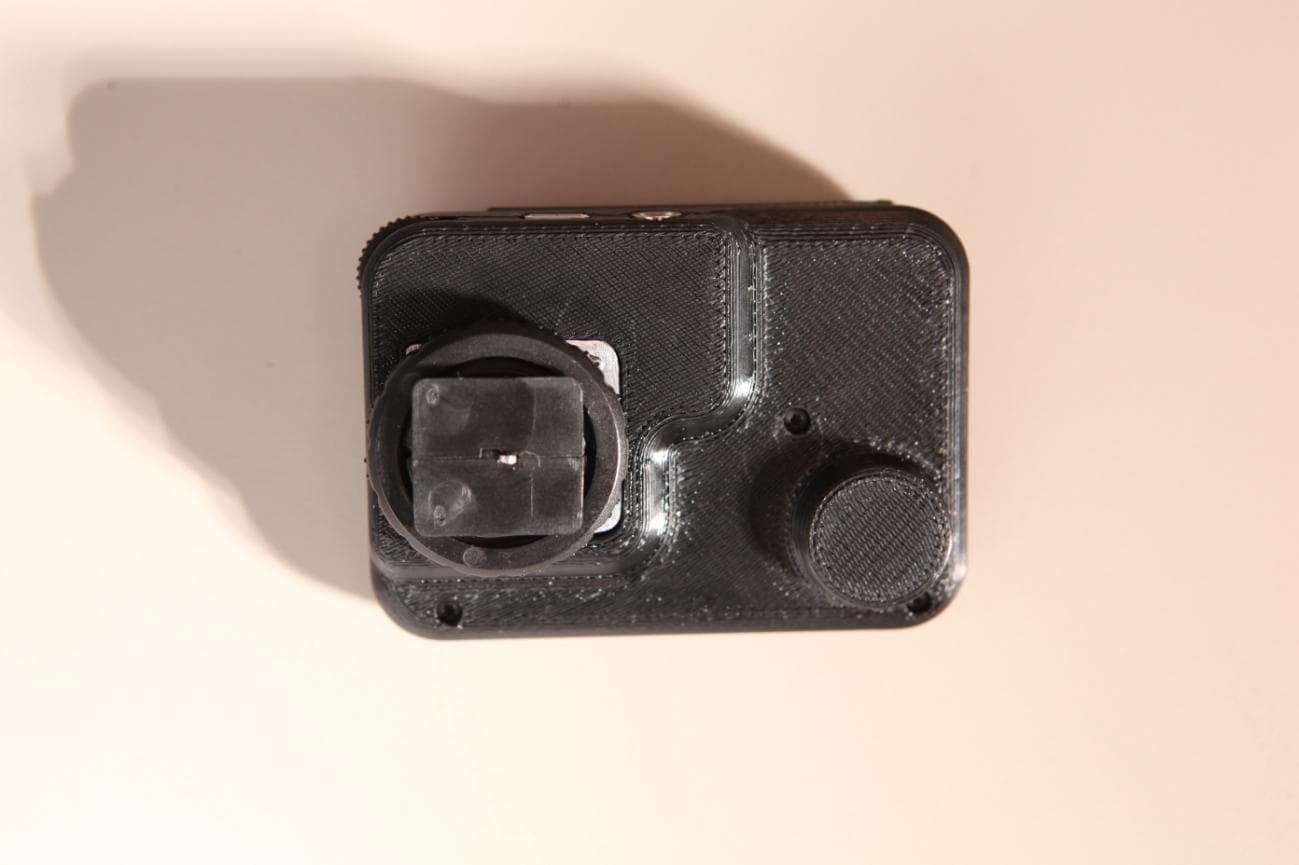
Click to zoom
Application Details
- Equipment Class
- DTS - Digital Transmission System
- Date of Grant
- Feb 12, 2014
- Application Purpose
- Original Equipment
- Date of Application
- Feb 12, 2014
- Equipment Note
- RadioPopper
- Frequency Range
- 903.75000000 - 926.00000000
- Company
- Leap Devices, LLC
- Country
- United States
Documents & Files
Document Text
Text extracted from the exhibit documents filed with the FCC. Open a document above to read the original.
Users Manual
Jr2 Transmitter Quick Start Guide Click 1234P P Button - Press and hold to power on/off - Tap to test fire Lighting Power Levels The Jr2 Transmitter is the most intuitive and easy to use lighting control device available. Click the dial inward to index between active groups. Turn dial to adjust value when frame is around desired group. When all groups are framed, all groups may be adjusted at the same time by the same value. When the lock is selected, any accidental movement of dial will not adjust power levels. Adjust Menu Settings PRESS and HOLD dial to enter menu mode. Click dial to move between options Rotate dial to make selection Channel: Set RadioPopper channel 1 to 16 Stops: Adjust by 1/3 or 1/10 stops. In percent mode, this changes between 1% and 5% adjustment intervals. Each group can be set to adjust by linear percent (similar to a JrX Transmitter dial) or more accurately by EV stops. SAVE and Recall Settings The Jr2 Transmitter includes 4 memory loca- tions to be used to store 4 complete lighting setups including all values and settings. Stored information includes the %/EV setting of each group, which groups are active, and whether the unit is set for 1/10 stop or 1/3 stop adjustments. The RadioPopper radio channel (1-16) is not stored in the memory locations. How to Save/Recall To save your present settings to a given memory location, simply press and hold the group button (1~4) corresponding to the memory location. After 2 seconds the word “SAVE” will blink along with the chosen location. Your settings are now stored. To recall previously saved settings, press and hold Dial inward for 2 seconds. While the “SAVE” icon is blinking, press and hold the group button (1~4) for 1 second corresponding to the memory location you wish to recall. Your set- tings will be recalled from the memory location. 1~4 Buttons - Toggle group on/off - Save/Recall SAVE settings Dial - Press and hold for MENU - Click to index, Rotate to set value TRANSMITTER Jr2 1234P FCC STATEMENT This equipment has been tested and found to comply with the limits for a class B digital device, pursuant to part 15 of the FCC Rules. These limits are designed to provide reasonable protection against harmful interference in a residential installation. This equipment generates, uses and can radiate radio frequency energy and if not installed and used in accordance with the instructions, may cause harmful interference to radio communications. However, there is no guarantee that interference will not occur in a particular installation. If this equipment does cause harmful interference to radio or television reception, which can be determined by turning the equipment off and on, the user is encouraged to try to correct the interference by one or more of the following measures: * Reorient or relocate the receiving antenna. * Increase the separation between the equipment and receiver. * Connect the equipment into an outlet on a circuit different from that to which the receiver is connected. * Consult the dealer or an experienced radio/TV technician for help. Operation with non-approved equipment is likely to result in interference to radio and TV reception. The user is cautioned that changes and modifications made to the equipment without the approval of manufacturer could void the user’s authority to operate this equipment. FCC ID: V4TJR2TX1 This device complies with Part 15 of the FCC Rules. Operation is subject to the following two conditions: (1) This device may not cause harmful interference and (2) this device must accept any interference received, including interference that may cause undesired operation. Important Note: To comply with FCC RF exposure compliance requirements, the following antenna installation and device operating configurations must be satisfied - This device and its antenna(s) must not be co-located or operating in conjunction with any other antenna or transmitter. INDUSTRY CANADA INFORMATION This device complies with Industry Canada licence-exempt RSS standard(s). Operation is subject to the following two conditions: (1) this device may not cause interference, and (2) this device must accept any interference, including interference that may cause undesired operation of the device. Le présent appareil est conforme aux CNR d’Industrie Canada applicables aux appareils radio exempts de licence. L’exploitation est autorisée aux deux conditions suivantes : (1) l’appareil ne doit pas produire de brouillage, et (2) l’utilisateur de l’appareil doit accepter tout brouillage radioélectrique subi, même si le brouillage est susceptible d’en compromettre le fonctionnement. Jr2 Receiver will adjust the associated light as finely as possible for the given light. When using the % scale, setting increments to 1/10 will allow power adjustment of 1% per increment. Setting increments to 1/3 will allow power adjustment of 5% per increment. using the % scale, a range from 00% to 99% is available. This scale is useful for users already familiar with the older model JrX Transmitter. Adjusting from 0% to 99% may be thought of as turning the dial of a JrX Transmitter between the high and low limits of the dial. Similarly, this % scale may be thought of as adjusting the power control slider of an Alien Bee light from one end to the other. To take advantage of the stop-accurate EV scale adjustment, a Jr2 Receiver is required. The older model JrX Receiver may still be used with the Jr2 Transmitter if you select the % scale for adjustment. 1/3 and 1/10 Increments You may choose to make adjustments in 1/3 stop intervals or 1/10 stop intervals. When the Jr2 Transmitter is configured to 1/3 stop increments and the group is set to EV mode, the 1/3 intervals will be approximated by setting to 0.7 and 0.3 increments. For example, starting at maximum power and adjusting downward, the settings will be 9.0, 8.7, 8.3, 8.0, and so on. When set to 1/10 stop increments, more fine control is possible. Con- sider however that some lighting de…
Text truncated - open the document above for the full version.
Cover Letter(s)
Correspondence by Project Project Number: Correspondence Number Memo V4TJR2TX1-1 1) The user manual provides an incomplete FCC statement. Please provide a corrected user manual. Please see the attached corrected user manual. 2) The EUT appears to have a USB port, however it was not connected during testing. Please explain the purpose of this port. This port is for service/diagnostic purposes only and is not used during transmit operation. Untitled Documenthttp://www.celectronics.com/CorrespondenceByProject.asp?ProjectNum... 1 of 12/10/2014 6:01 PM
ID Label/Location Info
Bottom Side of Device FCC Label 11.400 19.400 Model: Jr2 Tx FCC ID: V4TJR2TX1 IC: 7822A-JR2TX1 Sample Label Jr2 Tx Label SHEET 1 OF 1 REVDWG. NO. A SIZE TITLE: 5 4 3 2 1 1.0 Jr2 Tx Assembly - Label Location ALL DIMENSIONS ARE MILLIMETERS
RF Exposure Info
SAR Exclusion Justification This device FCC ID:is excluded from SAR testing by the following justification The maximum power that the transmitter is capable of is13.27mW Using the following formula from section 4.3.1 of KDB 447498at test separation distances ≤ 50 mm [(max. power of channel, including tune-up tolerance, mW) / (min. test separation distance, mm)] * [√f(GHz)] Duty Cycle 11.00% Value1-g (mW)10-g (mW) 2.52(113)123 "Value" is3, the SAR test exclusion threshold 1-g power limit10-g power limit 158394 “source-based” time-averaging based on an inherent property or duty-cycle of a device is allowed. An example of this is the determination of exposure from a device that uses digital technology such as a time-division multiple-access (TDMA) scheme for transmission < 50mm power limits for above caclulation using specified frequency V4TJR2TX1 Max Peak Power (dBm)Min Separation distance (mm)Frequency (Ghz) When the minimum test separation distance is < 5 mm, a distance of 5 mm according to 5) in section 4.1 is applied to determine SAR test exclusion. 0.90375511.23 SAREXJUST-B-0-43REV A01/21/2014
Test Report
Report Number: B31223D1 FCC Part 15 Subpart B and FCC Section 15.247 Test Report RadioPopper Model: Jr2 Tx Brea Division 114 Olinda Drive Brea, CA 92823 (714) 579-0500 Agoura Division 2337 Troutdale Drive Agoura, CA 91301 (818) 597-0600 Silverado Division 19121 El Toro Road Silverado, CA 92676 (949) 589-0700 Lake Forest Division 20621 Pascal Way Lake Forest, CA 92630 (949) 587-0400 Page 1 of 23 FCC PART 15, SUBPART B and C TEST REPORT for RADIOPOPPER MODEL: JR2 TX Prepared for LEAP DEVICES, LLC 229 EAST RESERVE STREET, #102 VANCOUVER, WASHINGTON 98661-3803 Prepared by:_____________________ KYLE FUJIMOTO Approved by:____________________ JAMES ROSS COMPATIBLE ELECTRONICS INC. 114 OLINDA DRIVE BREA, CALIFORNIA 92823 (714) 579-0500 DATE: JANUARY 18, 2013 REPORT APPENDICES TOTAL BODY A B C D E PAGES 23 2 2 2 11 49 86 This report shall not be reproduced except in full, without the written approval of Compatible Electronics. Report Number: B31223D1 FCC Part 15 Subpart B and FCC Section 15.247 Test Report RadioPopper Model: Jr2 Tx Brea Division 114 Olinda Drive Brea, CA 92823 (714) 579-0500 Agoura Division 2337 Troutdale Drive Agoura, CA 91301 (818) 597-0600 Silverado Division 19121 El Toro Road Silverado, CA 92676 (949) 589-0700 Lake Forest Division 20621 Pascal Way Lake Forest, CA 92630 (949) 587-0400 Page 2 of 23 TABLE OF CONTENTS Section / Title PAGE GENERAL REPORT SUMMARY 4 SUMMARY OF TEST RESULTS 5 1. PURPOSE 6 2. ADMINISTRATIVE DATA 7 2.1 Location of Testing 7 2.2 Traceability Statement 7 2.3 Cognizant Personnel 7 2.4 Date Test Sample was Received 7 2.5 Disposition of the Test Sample 7 2.6 Abbreviations and Acronyms 7 3. APPLICABLE DOCUMENTS 8 4. DESCIRPTION OF TEST CONFIGURATION 9 4.1 Description of Test Configuration - Emissions 9 4.1.1 Cable Construction and Termination 10 5. LISTS OF EUT, ACCESSORIES AND TEST EQUIPMENT 11 5.1 EUT and Accessory List 11 6. TEST SITE DESCRIPTION 13 6.1 Test Facility Description 13 6.2 EUT Mounting, Bonding and Grounding 13 7. CHARACTERISTICS OF THE TRANSMITTER 14 7.1 Transmitter Power 14 7.2 Channel Number and Frequencies 14 7.3 Antenna Gain 14 8. TEST PROCEDURES 15 8.1 RF Emissions 15 8.1.1 Conducted Emissions Test 15 8.1.2 Radiated Emissions (Spurious and Harmonics) Test 16 8.1.3 RF Emissions Test Results 18 8.2 Emissions Bandwidth (EBW) 19 8.3 Peak Output Power 20 8.4 RF Antenna Conducted Test 20 8.5 RF Band Edges 21 8.6 Spectral Density Test 22 9. CONCLUSIONS 23 Report Number: B31223D1 FCC Part 15 Subpart B and FCC Section 15.247 Test Report RadioPopper Model: Jr2 Tx Brea Division 114 Olinda Drive Brea, CA 92823 (714) 579-0500 Agoura Division 2337 Troutdale Drive Agoura, CA 91301 (818) 597-0600 Silverado Division 19121 El Toro Road Silverado, CA 92676 (949) 589-0700 Lake Forest Division 20621 Pascal Way Lake Forest, CA 92630 (949) 587-0400 Page 3 of 23 LIST OF APPENDICES APPENDIX TITLE A Laboratory Accreditations and Recognitions B Modifications to the EUT C Additional Models Covered Under This Report D Diagrams and Charts Test Setup Diagrams Antenna and Effective Gain Factors E Data Sheets LIST OF FIGURES FIGURE TITLE 1 Conducted Emissions Test Setup 2 Plot Map And Layout of Test Site Report Number: B31223D1 FCC Part 15 Subpart B and FCC Section 15.247 Test Report RadioPopper Model: Jr2 Tx Brea Division 114 Olinda Drive Brea, CA 92823 (714) 579-0500 Agoura Division 2337 Troutdale Drive Agoura, CA 91301 (818) 597-0600 Silverado Division 19121 El Toro Road Silverado, CA 92676 (949) 589-0700 Lake Forest Division 20621 Pascal Way Lake Forest, CA 92630 (949) 587-0400 Page 4 of 23 GENERAL REPORT SUMMARY This electromagnetic emission test report is generated by Compatible Electronics Inc., which is an independent testing and consulting firm. The test report is based on testing performed by Compatible Electronics personnel according to the measurement procedures described in the test specifications given below and in the "Test Procedures" section of this report. The measurement data and conclusions appearing herein relate only to the sample tested and this report may not be reproduced without the written permission of Compatible Electronics, unless done so in full. This report must not be used to claim product endorsement by NVLAP or any other agency of the U.S. Government. Device Tested: RadioPopper Model: Jr2 Tx S/N: N/A Product Description: See Expository Statement. Modifications: The EUT was not modified during the testing. Customer: Leap Devices, LLC 229 East Reserve Street, #102 Vancouver, Washington 98661-3803 Test Dates: December 23, 27, and 30, 2013 Test Specifications : EMI requirements CFR Title 47, Part 15, Subpart B; and Subpart C, sections 15.205, 15.209, and 15.247 Test Procedure: ANSI C63.4 and ANSI C63.10 Test Deviations: The test procedure was not deviated from during the testing. Report Number: B31223D1 FCC Part 15 Subpart B and FCC Section 15.247 Test Report RadioPopper Model: Jr2 Tx Brea Division 114 Olinda Drive Brea, CA 92823 (714) 579-0500 Agoura Division 2337 Troutdale Drive Agoura, CA 91301 (818) 597-0600 Silverado Division 19121 El Toro Road Silverado, CA 92676 (949) 589-0700 Lake Forest Division 20621 Pascal Way Lake Forest, CA 92630 (949) 587-0400 Page 5 of 23 SUMMARY OF TEST RESULTS TEST DESCRIPTION RESULTS 1 Conducted RF Emissions, 150 kHz – 30 MHz This test was not performed because the EUT is a battery powered device and cannot be plugged into the AC public mains. 2 Spurious Radiated RF Emissions, 30 MHz – 1000 MHz Complies with the Class B limits of CFR Title 47, Part 15 Subpart B; and the limits of CFR Title 47, Part 15, Subpart C, section 15.209 3 Spurious Radiated RF Emissions, 10 kHz – 30 MHz and 1000 MHz – 9.3 GHz Complies with the Class B limits of CFR Title 47, Part 15, Subpart B; and CFR Title 47, Part 15, Subpart C, section 15.247(d) 4 Fundamental and Emissions produced by the intentional radiator in non-restricted bands, 10 kHz – 9.3 GHz Complies with the relevant requirements of CFR Title 47, Part 15, Subpart…
Text truncated - open the document above for the full version.
Contact Information
Applicant
Kevin King(Director)
Technical Contact
Compatible Electronics, Inc.Kyle Fujimoto
[email protected]714-579-0500
114 Olinda Drive · Brea, California · United States
Test Firm
Compatible Electronics, Inc.Michael Christensen
Technical Specifications
| # | Rule Parts | Frequency Range | Power Output |
|---|---|---|---|
| 1 | 15C | 903.75 MHz - 926 MHz | 13.27 mW |
Other Applications from Leap Devices, LLC
V4TSKT1
Mar 23, 2014SK Meter Module
Equipment Class
DXX - Part 15 Low Power Communication Device Transmitter
V4TRPP1TX770US
Apr 09, 2008Radio Popper P1 Transmitter
Equipment Class
DXX - Part 15 Low Power Communication Device Transmitter