V4TRPP1TX770USRadio Popper P1 Transmitter
Leap Devices, LLC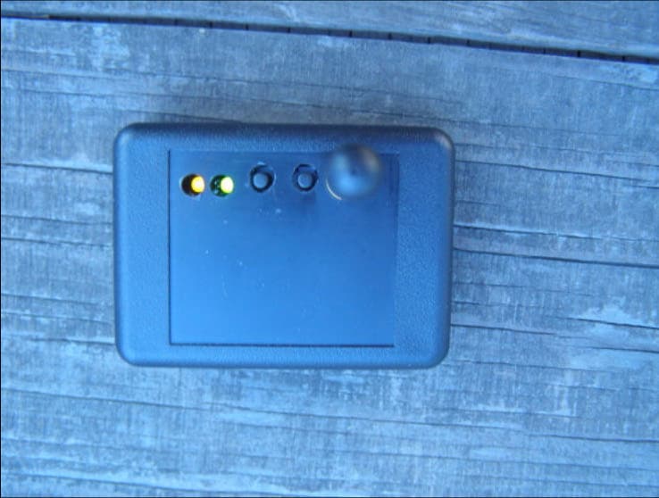
Click to zoom
Application Details
- Equipment Class
- DXX - Part 15 Low Power Communication Device Transmitter
- Date of Grant
- Apr 09, 2008
- Application Purpose
- Original Equipment
- Date of Application
- Apr 09, 2008
- Equipment Note
- Radio Popper P1 Transmitter
- Frequency Range
- 916.50000000 - 916.50000000
- Company
- Leap Devices, LLC
- Country
- United States
Documents & Files
Document Text
Text extracted from the exhibit documents filed with the FCC. Open a document above to read the original.
Users Manual
RadioPopper P1 Radio Wireless Owners Manual Page 2 RadioPopper is owned and manufactured by Leap Devices, LLC in Phoenix Arizona. This product was designed, produced, and manufactured in the USA. PRODUCT PATENT PENDING Copyright 2007-2008, Leap Devices LLC, All Rights Reserved Leap Devices LLC, 20987 N. John Wayne Pkwy. Suite B-104-207, Maricopa, AZ 85239 FCC ID: V4TRPP1TX770US This device complies with Part 15 of the FCC Rules. Operation is subject to the following two conditions: (1) This device may not cause harmful interference and (2) this device must accept any interference received, including interference that may cause undesired operation. FCC STATEMENT This equipment has been tested and found to comply with the limits for a class B digital device, pursuant to part 15 of the FCC Rules. These limits are designed to provide reason- able protection against harmful interference in a residential installation. This equipment generates, uses and can radiate radio frequency energy and if not installed and used in accordance with the instructions, may cause harmful interference to radio communications. However, there is no guarantee that interference will not occur in a particular installation. If this equipment does cause harmful interference to radio or television reception, which can be determined by turning the equipment off and on, the user is encouraged to try to correct the interference by one or more of the following measures: * Reorient or relocate the receiving antenna. * Increase the separation between the equipment and receiver. * Connect the equipment into an outlet on a circuit different from that to which the receiver is connected. * Consult the dealer or an experienced radio/TV technician for help. This equipment has been verified to comply with the limits for a class B computing device, pursuant to FCC Rules. Operation with non-approved equipment is likely to result in inter- ference to radio and TV reception. The user is cautioned that changes and modifications made to the equipment without the approval of manufacturer could void the user’s authority to operate this equipment. Table of Contents Page 3 Introduction . . . . . . . . . . . . . . . . . . . . . . . . . . . . . . . . . . . . . . . . . . . . . . . . . . . . . Specifications and Warnings . . . . . . . . . . . . . . . . . . . . . . . . . . . . . . . . . . . . . . . Parts Descriptions . . . . . . . . . . . . . . . . . . . . . . . . . . . . . . . . . . . . . . . . . . . . . . . . Installation . . . . . . . . . . . . . . . . . . . . . . . . . . . . . . . . . . . . . . . . . . . . . . . . . . . . . Slave Flash Optic Placement . . . . . . . . . . . . . . . . . . . . . . . . . . . . . . . . . . . . . . . Operating Instructions . . . . . . . . . . . . . . . . . . . . . . . . . . . . . . . . . . . . . . . . . . . Sync Interval Adjustment . . . . . . . . . . . . . . . . . . . . . . . . . . . . . . . . . . . . . . . . . Trouble Shooting . . . . . . . . . . . . . . . . . . . . . . . . . . . . . . . . . . . . . . . . . . . . . . . . Miscellaneous Tips . . . . . . . . . . . . . . . . . . . . . . . . . . . . . . . . . . . . . . . . . . . . . . 4 6 8 10 14 16 20 22 26 Introduction Thank you for your purchase of the RadioPopper P1 wireless radio system. This product represents much development and lots of thinking outside the box. This system was developed by a “regular guy” with an electronics background - a wedding photographer from Arizona seeking to bridge the weak link of existing wireless systems - the need to maintain a “line of sight” between master and slave flash units. We hope this new tool brings a great new dynamic to your work and how you use your lighting. In short, the RadioPopper P1 system allows you to use the automatic and high-speed sync functions built into your existing flash units without concern of whether or not the master and slave units can “see” each other. You now have the ability to place your lights wherever you choose, then controlling the output power of each slave flash from the camera body manually or automatically via your camera’s ETTL or iTTL logic system. It’s also the world’s first product to effectively provide you high speed sync by radio. That’s a major step forward. Enjoy. Each aspect of this system has been well thought out to accomplish the nearly impossible task of reproducing an extremely fast communica- tion with exacting timing while at the same time remaining simple and intuitive for the user to install and operate. Please read this short manual entirely before installing or operating your RadioPopper P1 wireless system. Proper installation is key to correct operation. If you have any troubles along the way, feel free to call or email. RadioPopper P1 Radio Wireless System Page 4 How It Works Your current master and slave wireless flash system continues to function just as it always has. That’s the beauty and simplicity of the RadioPopper P1 system. The RadioPopper P1 Transmitter “listens” to the light signal being created inside the master flash unit or remote commander on your camera’s hot shoe. The P1 Transmitter sends this signal over the radio where it is read by the RadioPopper P1 Receiver. The receiver then uses it’s own internal light source to “reproduce” this light signal. The light is sent down the flexible fiber optic cable where it lights a small nylon bead at the end. When this bead is placed over the infrared sensor on a slave flash - that slave flash responds to the “reproduced” light signal just as it normally would had it seen the light directly from the master flash. Installation couldn’t be more simple. Just place the RadioPopper P1 Transmitter on top of your master flash or IR commander device using the included Velcro pads. “Look Ma! No wires!” On the receiving end, add a P1 Receiver in a similar way, anchor the optic bead over the infrared sensor on your slave flash and you’re all done. No wires or adaptors and no complicated system to re-learn. Now just pow…
Text truncated - open the document above for the full version.
ID Label/Location Info
Product Label Exhibit, Actual Size Product Label Placed on device exterior. Device and label Actual Size
Test Report
Report Number: B80226D2 FCC 15.249 Test Report Radio Popper P1 Transmitter Model: P1 Brea Division 114 Olinda Drive Brea, CA 92823 (714) 579-0500 Agoura Division 2337 Troutdale Drive Agoura, CA 91301 (818) 597-0600 Silverado Division 19121 El Toro Road Silverado, CA 92676 (949) 589-0700 Lake Forest Division 20621 Pascal Way Lake Forest, CA 92630 (949) 587-0400 Page 1 of 15 FCC PART 15 SUBPART C TEST REPORT for RADIO POPPER P1 TRANSMITTER Model: P1 Prepared for LEAP DEVICES, LLC. 20987 N. JOHN WAYNE PARKWAY, SUITE B-104-207 MARICOPA, ARIZONA, 85239 Prepared by: _____________________ BRANDON TAYLOR Approved by: ____________________ MICHAEL CHRISTENSEN COMPATIBLE ELECTRONICS INC. 114 OLINDA DRIVE BREA, CALIFORNIA 92823 (714) 579-0500 DATE: MARCH 12, 2008 REPORT APPENDICES TOTAL BODY A B C D E PAGES 15 2 2 2 11 4 36 This report shall not be reproduced except in full, without the written approval of Compatible Electronics. Report Number: B80226D2 FCC 15.249 Test Report Radio Popper P1 Transmitter Model: P1 Brea Division 114 Olinda Drive Brea, CA 92823 (714) 579-0500 Agoura Division 2337 Troutdale Drive Agoura, CA 91301 (818) 597-0600 Silverado Division 19121 El Toro Road Silverado, CA 92676 (949) 589-0700 Lake Forest Division 20621 Pascal Way Lake Forest, CA 92630 (949) 587-0400 Page 2 of 15 TABLE OF CONTENTS Section / Title PAGE GENERAL REPORT SUMMARY 4 SUMMARY OF TEST RESULTS 4 1. PURPOSE 5 2. ADMINISTRATIVE DATA 6 2.1 Location of Testing 6 2.2 Traceability Statement 6 2.3 Cognizant Personnel 6 2.4 Date Test Sample was Received 6 2.5 Disposition of the Test Sample 6 2.6 Abbreviations and Acronyms 6 3. APPLICABLE DOCUMENTS 7 4. DESCRIPTION OF TEST CONFIGURATION 8 4.1 Description of Test Configuration – EMI 8 4.1.1 Cable Construction and Termination 9 5. LISTS OF EUT, ACCESSORIES AND TEST EQUIPMENT 10 5.1 EUT and Accessory List 10 5.2 EMI Test Equipment 11 6. TEST SITE DESCRIPTION 12 6.1 Test Facility Description 12 6.2 EUT Mounting, Bonding and Grounding 12 6.3 Facility Environmental Characteristics 12 7. TEST PROCEDURES 13 7.1 RF Emissions 13 7.1.1 Radiated Emissions (Spurious and Harmonics) Test 13 7.2 Radiated Emissions (Spurious and Harmonics) Test (continued) 14 8. CONCLUSIONS 15 Report Number: B80226D2 FCC 15.249 Test Report Radio Popper P1 Transmitter Model: P1 Brea Division 114 Olinda Drive Brea, CA 92823 (714) 579-0500 Agoura Division 2337 Troutdale Drive Agoura, CA 91301 (818) 597-0600 Silverado Division 19121 El Toro Road Silverado, CA 92676 (949) 589-0700 Lake Forest Division 20621 Pascal Way Lake Forest, CA 92630 (949) 587-0400 Page 3 of 15 LIST OF APPENDICES APPENDIX TITLE A Laboratory Recognitions B Modifications to the EUT C Additional Models Covered Under This Report D Diagram, Charts, and Photos • Test Setup Diagram • Antenna and Amplifier Factors • Radiated Emission Photos E Data Sheets LIST OF FIGURES FIGURE TITLE 1 Plot Map And Layout of the Radiated Test Site Report Number: B80226D2 FCC 15.249 Test Report Radio Popper P1 Transmitter Model: P1 Brea Division 114 Olinda Drive Brea, CA 92823 (714) 579-0500 Agoura Division 2337 Troutdale Drive Agoura, CA 91301 (818) 597-0600 Silverado Division 19121 El Toro Road Silverado, CA 92676 (949) 589-0700 Lake Forest Division 20621 Pascal Way Lake Forest, CA 92630 (949) 587-0400 Page 4 of 15 GENERAL REPORT SUMMARY Compatible Electronics Inc. generates this electromagnetic emission test report, which is an independent testing and consulting firm. The test report is based on testing performed by Compatible Electronics personnel according to the measurement procedures described in the test specifications given below and in the "Test Procedures" section of this report. The measurement data and conclusions appearing herein relate only to the sample tested and this report may not be reproduced without the written permission of Compatible Electronics, unless done so in full. This report must not be used to claim product endorsement by NVLAP, NIST or any other agency of the U.S. Government. Device Tested: Radio Popper P1 Transmitter Model: P1 S/N: N/A Product Description: The EUT is a transmitter. Modifications: The EUT was not modified during testing. Manufacturer: Leap Devices, LLC 20987 N. John Wayne Pkwy, Suite B-104-207 Maricopa, Arizona, 85239 Test Date: February 26, 2008 Test Specifications: EMI requirements CFR Title 47, Part 15, Subpart B, and Subpart C, Section 15.205, 15.209 and 15.249 Test Procedure: ANSI C63.4 Test Deviations: The test procedure was not deviated from during the testing. SUMMARY OF TEST RESULTS TEST DESCRIPTION RESULTS 1 Radiated RF Emissions, 10 KHz – 9300 MHz Complies with the Class B limits of CFR Title 47, Part 15, Subpart B and Subpart C, sections 15.205, 15.209, and 15.249 Highest Reading in Relation to Spec Limit: 48.91 dBμV @ 1833.00 MHz (*U c = 2.39 dB) Report Number: B80226D2 FCC 15.249 Test Report Radio Popper P1 Transmitter Model: P1 Brea Division 114 Olinda Drive Brea, CA 92823 (714) 579-0500 Agoura Division 2337 Troutdale Drive Agoura, CA 91301 (818) 597-0600 Silverado Division 19121 El Toro Road Silverado, CA 92676 (949) 589-0700 Lake Forest Division 20621 Pascal Way Lake Forest, CA 92630 (949) 587-0400 Page 5 of 15 1. PURPOSE This document is a qualification test report based on the Electromagnetic Interference (EMI) tests performed on the Radio Popper P1 Transmitter, Model: P1. The EMI measurements were performed according to the measurement procedure described in ANSI C63.4. The tests were performed in order to determine whether the electromagnetic emissions from the equipment under test, referred to as EUT hereafter, are within the specification limits defined by CFR Title 47, Part 15, Subpart C, sections 15.205, 15.209, and 15.249. Report Number: B80226D2 FCC 15.249 Test Report Radio Popper P1 Transmitter Model: P1 Brea Division 114 Olinda Drive Brea, CA 92823 (714) 579-0500 Agoura Division 2337 Troutdale Drive Agoura, CA 91301 (818) 597-0600 Silverado Division 19121 El Toro Road Silverado, CA…
Text truncated - open the document above for the full version.
Contact Information
Applicant
Kevin King(Director)
Technical Contact
Compatible ElectronicsKyle Fujimoto
[email protected]714-579-0500
114 Olinda Drive · Brea, California · United States
Test Firm
Compatible Electronics, Inc.Ruby Hall
[email protected]805-480-4044
Technical Specifications
| # | Rule Parts | Frequency Range | Power Output |
|---|---|---|---|
| 1 | 15C | 916.5 MHz - 916.5 MHz | - |
Other Applications from Leap Devices, LLC
V4TSKT1
Mar 23, 2014SK Meter Module
Equipment Class
DXX - Part 15 Low Power Communication Device Transmitter
V4TJR2TX1
Feb 12, 2014RadioPopper
Equipment Class
DTS - Digital Transmission System