V8NZRB1000127ZigBee to RS485 Bridge (ZRB)
Autani, LLC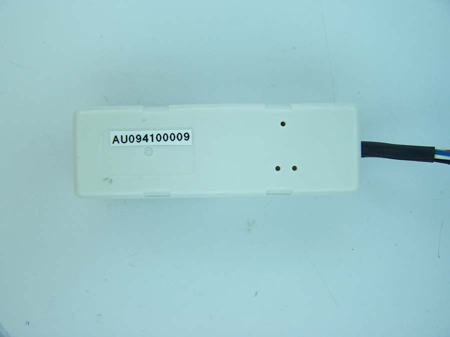
Click to zoom
Application Details
- Equipment Class
- DTS - Digital Transmission System
- Date of Grant
- Dec 15, 2009
- Application Purpose
- Original Equipment
- Date of Application
- Dec 15, 2009
- Equipment Note
- ZigBee to RS485 Bridge (ZRB)
- Frequency Range
- 2405.00000000 - 2480.00000000
- Company
- Autani, LLC
- Country
- United States
Documents & Files
Document Text
Text extracted from the exhibit documents filed with the FCC. Open a document above to read the original.
Users Manual
Users Manual ZigBee to RS485 Bridge (ZRB) 1000127-01 Document Number: 80027 7125 Columbia Gateway Drive, Suite 200 Columbia, MD 21046 CONFIDENTIAL AND PROPRIETARY The information contained in this document is proprietary and confidential information of Autani Corporation. Any use of this information without the expressed written consent of Autani Corporation is prohibited. ZigBee to RS485 Bridge (ZRB) Users Manual 1. Description CONFIDENTIAL AND PROPRIETARY The information contained in this document is proprietary and confidential information of Autani Corporation. Any use of this information without the expressed written consent of Autani Corporation is prohibited. 2 of 7 Version Date Changed By Revision Description 1 16-Nov-2009 JAD Initial Release Table of Contents 1. Description ...............................................................................................................3 2. Ordering Informatio n ...............................................................................................4 3. Specifications...........................................................................................................4 3.1 Absolute Maximum Ratings...........................................................................................................4 3.2 Recommended Operating Conditions ...........................................................................................4 3.3 DC Electrical Specifications ..........................................................................................................4 3.4 RF Electrical Characteristics .........................................................................................................5 4. Physical Interface ....................................................................................................5 5. Certifications ............................................................................................................6 5.1 FCC – United State .......................................................................................................................6 5.2 IC – Canada ..................................................................................................................................6 6. Theory of Operation.................................................................................................7 ZigBee to RS485 Bridge (ZRB) Users Manual 1. Description CONFIDENTIAL AND PROPRIETARY The information contained in this document is proprietary and confidential information of Autani Corporation. Any use of this information without the expressed written consent of Autani Corporation is prohibited. 3 of 7 1. Description The ZigBee to RS485 Bridge (ZRB) provides a cost-effective path to wirelessly enable many devices which still use wired commutations channels. The wireless side of the ZRB employs an RF transceiver in the 2.4 GHz ISM band based on the IEEE 802.15.4 wireless network protocol. The wired side of the ZRB communicates in full or half duplex differential modes (i.e. RS485 or RS422). Features FCC (V8NZRB1000127) and IC (7737A-ZRB1000127) certified Approximately 500 ft LOS transmit/receive distance ZigBee to RS485 Bridge (ZRB) Users Manual 2. Ordering Information CONFIDENTIAL AND PROPRIETARY The information contained in this document is proprietary and confidential information of Autani Corporation. Any use of this information without the expressed written consent of Autani Corporation is prohibited. 4 of 7 2. Ordering Information Part Number Ordering Number Description ZRB1000127 1000127-01 Aprilaire 8870 Thermostat Interface Module ZRB1000127 1000127-02 Jackson System’s T-32-P Thermostat Interface Module ZRB1000127 1000127-05 National Meter Interface Module 3. Specifications 3.1 Absolute Maximum Ratings Note: Exceeding the maximum ratings may cause permanent damage to the unit Parameter Test Condition Min. Max. Unit Input Voltage (Vdd) -150 50 V Voltage on Signal Pin (Rx+, Rx-, Tx+, Tx-) -9 14 V Storage Temperature -25 80 o C 3.2 Recommended Operating Conditions Note: Operating conditions outside those listed here may cause inappropriate and unpredictable behavior. Parameter Test Condition Min. Max. Unit Input Voltage (Vdd) At 25 o C 9 40 VDC Input Voltage (Vdd) At 25 o C 9 28 VAC Operating Temperature 0 60 o C 3.3 DC Electrical Specifications Test conditions unless otherwise specified: at 25 o C, Vdd = 24VAC, No load on RS485 Bus, LEDs off. Parameter Test Condition Typ. Max. Unit Operational Current Input Current (Idd) 25 31 mA ZigBee to RS485 Bridge (ZRB) Users Manual 4. Physical Interface CONFIDENTIAL AND PROPRIETARY The information contained in this document is proprietary and confidential information of Autani Corporation. Any use of this information without the expressed written consent of Autani Corporation is prohibited. 5 of 7 3.4 RF Electrical Characteristics Parameter Test Condition Min. Typ. Max. Unit Frequency Range At 25 o C 2400 2500 MHz Sensitivity 1% PER, 20byte packet defined by IEEE 802.15.4 -99 -94 dBm High-side Adjacent Channel Rejection IEEE 802.15.4 signal at -82 dBm 35 dB Low-side Adjacent Channel Rejection IEEE 802.15.4 signal at -82 dBm 35 dB Other Channel Rejection IEEE 802.15.4 signal at -82 dBm 40 dB 802.11g Rejection centered at +12MHz or -13MHz 35 dB Maximum Input Signal Strength 0 dBm Relative Frequency Error -120 120 ppm 4. Physical Interface All signals are from the perspective of the ZRB. Wire Number Color Signal Name Description 1 No wire present - Reserved for future feature expansion 2 Red PWR Input power of the ZRB 3 Blue Rx+ Positive half of the Receiver differential pair 4 White Rx- Negative half of the Receiver differential pair 5 Yellow Tx- Negative half of the Transmitter differential pair 6 Green Tx+ Positive half of the Transmitter differential pair 7 Black GND Input ground and RS485 reference of the ZRB 8 No wire present - Reserved for future feature expansion ZigBee to RS485 Bridge (ZRB) Users Manual 5. C…
Text truncated - open the document above for the full version.
Cover Letter(s)
7125 Columbia Gateway Drive, Suite 200 Columbia, MD 21046 December 2, 2009 REF: EMC27595-FCC247 To whom it may concern: The ZigBee to RS485 Bridge, ZRB, is physically too small to support a label indicating the appropriate language as called out by the FCC. In order to meet this label requirement the language is included in the Users Manual, ZigBee to RS485 Bridge: document number 80027. It can be found in section 5 Certifications, under Note 3. This note is included herein for reference. NOTE 3: This device complies with part 15 of the FCC Rules. Operation is subject to the following two conditions: (1) This device may not cause harmful interference, and (2) this device must accept any interference received, including interference that may cause undesired operation Sincerely, Henry Martin Engineering Director Autani Corporation
ID Label/Location Info
7125 Columbia Gateway Drive, Suite 200 Columbia, MD 21046 December 2, 2009 REF: EMC27595-FCC247 To whom it may concern: The ZigBee to RS485 Bridge, ZRB, uses the following label to display the mandated FCC information. The label is located on the top of the unit as depicted in the following rendering. Sincerely, Henry Martin Engineering Director Autani Corporation
RF Exposure Info
Application Note AN043 Small Size 2.4 GHz PCB antenna By Audun Andersen 1 KEYWORDS • CC25xx • CC24xx • CC2480 • PCB antenna • USB dongle • 2.4 GHz • Inverted F Antenna 2 INTRODUCTION The PCB antenna used on the CC2511 USB dongle reference design is described in this application note. Even if the antenna presented is for a USB dongle design it can be used in all 2.4 GHz designs, especially where small space is required for the antenna. This application note describes the antenna dimensions, the RF performance and considerations for complying with regulatory limits when using this design. The suggested antenna design requires no more than 15.2 x 5.7 mm of space and ensures a VSWR ratio of less than 2 across the 2.4 GHz ISM band when connected to a 50 ohm source. Figure 1: CC2511 USB Dongle SWRA117D Page 1 of 21 Application Note AN043 Table of Contents 1 KEYWORDS...................................................................................................................1 2 INTRODUCTION.............................................................................................................1 3 ABBREVIATIONS...........................................................................................................2 4 ANTENNA DESIGN........................................................................................................3 4.1 DESIGN GOALS..........................................................................................................3 4.2 SIMULATION...............................................................................................................3 4.3 LAYOUT AND IMPLEMENTATION...................................................................................4 5 TEST RESULTS.............................................................................................................5 5.1 REFLECTION..............................................................................................................5 5.2 RADIATION PATTERN..................................................................................................7 5.3 OUTPUT POWER......................................................................................................15 5.4 SPURIOUS EMISSION AND HARMONICS......................................................................17 6 CONCLUSION ..............................................................................................................20 7 GENERAL INFORMATION..........................................................................................21 7.1 DOCUMENT HISTORY................................................................................................21 3 ABBREVIATIONS CAD Computer Aided Design CC24xx CC2400, CC2420, CC2430 and CC2431 CC25xx CC2500, CC2510, CC2511, CC2550 and CC2520 CC2480 Z-Accel ZigBee Processor IFA Inverted F Antenna ISM Industrial, Scientific and Medical LOS Line Of Sight PCB Printed Circuit Board PER Packet Error Rate VSWR Voltage Standing Wave Ratio SWRA117D Page 2 of 21 Application Note AN043 4 ANTENNA DESIGN The PCB antenna on the CC2511 USB dongle reference design is a meandered Inverted F Antenna (IFA). The IFA was designed to match an impedance of 50 ohm at 2.45 GHz. Thus no additional matching components are necessary. 4.1 Design Goals The reflection at the feed point of the antenna determines how much of the applied power is delivered to the antenna. A reflection of less than -10 dB across the 2.4 GHz ISM band, when connected to a 50 ohm source, was a design goal. Reflection of less than -10 dB, or VSWR less than 2, ensures that more than 90% of the available power is delivered to the antenna. Bandwidth is in this document defined as the frequency band where more than 90% of the available power is delivered to the antenna. Another design goal was to fit the size of the PCB antenna on a USB dongle and to obtain good performance also when the dongle is connected to a computer. 4.2 Simulation IE3D from Zeland, which is an electromagnetic simulation tool, was used to design the antenna. The accuracy of the simulation is controlled by the mesh. An increase of the mesh increases the simulation time. Thus, for initial simulations mesh = 1 should be used. When a fairly good result is achieved a higher mesh should be used to obtain more accurate results. Comparison of simulation and measurement results shows that the measured reflection is between the result obtained with mesh = 5 and mesh = 1; see Figure 2 for details. Figure 2: Comparison of Simulation and Measurements Results SWRA117D Page 3 of 21 Application Note AN043 4.3 Layout and Implementation Small changes of the antenna dimensions may have large impact on the performance. Therefore it is strongly recommended to make an exact copy of the reference design to achieve optimum performance. The easiest way to implement the antenna is to import the gerber or DXF file showing the antenna layout. These files are named IFA_USB.spl and IFA_USB.dxf respectively and are included in the CC2511 USB dongle reference design available from http://www.ti.com\lpw. The imported file can be used as a template when drawing the antenna. By using this procedure it should be possible to make an exact copy. If the PCB CAD tool being used does not support import of DXF or gerber files, Figure 3 and Table 1 should be used to ensure correct implementation. It is recommended to generate a gerber file for comparison with IFA_USB.spl when making a manual implementation. Most gerber viewers have the possibility to import several gerber files at the same time. Thus by placing the gerber file, showing the manually implemented antenna, on top of IFA_USB.spl it is easy to verify that the antenna is correctly implemented. It is also recommended to use the same thickness and type of PCB material as used in the reference design. Information about the PCB can be found in a separate readme file included in the reference design. To compensate for a thicker/thinner P…
Text truncated - open the document above for the full version.
RF Exposure Info
§ 15.247(b) RF Exposure RF Exposure Requirements: §1.1307(b)(1) and §1.1307(b)(2): Systems operating under the provisions of this section shall be operated in a manner that ensures that the public is not exposed to radio frequency energy levels in excess of the Commission’s guidelines. RF Radiation Exposure Limit: §1.1310: As specified in this section, the Maximum Permissible Exposure (MPE) Limit shall be used to evaluate the environmental impact of human exposure to radiofrequency (RF) radiation as specified in Sec. 1.1307(b), except in the case of portable devices which shall be evaluated according to the provisions of Sec. 2.1093 of this chapter. MPE Limit Calculation: EUT’s operating frequencies between 2400 and 2483.5 MHz ;. Highest radiated power (EIRP) = 0.82 dBm. Therefore, Limit for Uncontrolled exposure: 1 mW/cm 2 . Equation from page 18 of OET 65, Edition 97-01 S = EIRP / 4R 2 where, S = Power Density mW/m 2 EIRP = Equivalent Isotropic Radiated Power R = Distance to the center of radiation of the antenna (20 cm for Mobile minimum distance) EIRP = 1.2 mW S = 1.2 / 4(3.1416)(20) 2 S = 0.00024 mW/cm 2 Therefore, EUT meets the Uncontrolled Exposure limit.
Test Report
MET Laboratories, Inc. Safety Certification - EMI - Telecom Environmental Simulation 914 WEST PATAPSCO AVENUE ! BALTIMORE, MARYLAND 21230-3432 ! PHONE (410) 354-3300 ! FAX (410) 354-3313 33439 WESTERN AVENUE ● UNION CITY, CALIFORNIA 94587 ● PHONE (510) 489-6300 ● FAX (510) 489-6372 3162 BELICK STREET ● SANTA CLARA, CALIFORNIA 95054 ● PHONE (408 748-3585 ● FAX (510) 489-6372 The Nation’s First Licensed Nationally Recognized Testing Laboratory December 11, 2009 Autani Corp 7125 Columbia Gateway Drive Columbia, MD 21046 Dear Jason Dunahoo, Enclosed is the EMC Wireless test report for compliance testing of the Autani Corp, ZigBee to RS485 Bridge (ZRB) as tested to the requirements of Title 47 of the CFR, Ch. 1 (10-1-06 ed.), Part 15, Subpart B, ICES-003, Issue 4 February 2004 for a Class B Digital Device and FCC Part 15 Subpart C, RSS-210, Issue 7, June 2007 for Intentional Radiators. Thank you for using the services of MET Laboratories, Inc. If you have any questions regarding these results or if MET can be of further service to you, please feel free to contact me. Sincerely yours, MET LABORATORIES, INC. Jennifer Warnell Documentation Department Reference: (\Autani Corp\EMC27595-FCC247 Rev. 1) Certificates and reports shall not be reproduced except in full, without the written permission of MET Laboratories, Inc. Electromagnetic Compatibility Autani Corp Cover Page ZigBee to RS485 Bridge (ZRB) CFR Title 47, Part 15B, 15.247; RSS-210, Issue 7, June 2007 & ICES-003 MET Report: EMC27595-FCC247 Rev. 1 © 2009, MET Laboratories, Inc. Page ii of vii Electromagnetic Compatibility Criteria Test Report for the Autani Corp ZigBee to RS485 Bridge (ZRB) Tested under the FCC Certification Rules contained in Title 47 of the CFR, Parts 15 Subpart B & ICES-003 for Class B Digital Devices & 15.247 Subpart C & RSS-210, Issue 7, June 2007 for Intentional Radiators MET Report: EMC27595-FCC247 Rev. 1 December 11, 2009 Prepared For: Autani Corp 7125 Columbia Gateway Drive Columbia, MD 21046 Prepared By: MET Laboratories, Inc. 914 W. Patapsco Ave. Baltimore, MD 21230 Electromagnetic Compatibility Autani Corp Cover Page ZigBee to RS485 Bridge (ZRB) CFR Title 47, Part 15B, 15.247; RSS-210, Issue 7, June 2007 & ICES-003 MET Report: EMC27595-FCC247 Rev. 1 © 2009, MET Laboratories, Inc. Page iii of vii Electromagnetic Compatibility Criteria Test Report for the Autani Corp ZigBee to RS485 Bridge (ZRB) Tested under the FCC Certification Rules contained in Title 47 of the CFR, Parts 15 Subpart B & ICES-003 for Class B Digital Devices & 15.247 Subpart C & RSS-210, Issue 7, June 2007 for Intentional Radiators Dusmantha Tennakoon, Project Engineer Jennifer Warnell Electromagnetic Compatibility Lab Documentation Department Engineering Statement: The measurements shown in this report were made in accordance with the procedures indicated, and the emissions from this equipment were found to be within the limits applicable. I assume full responsibility for the accuracy and completeness of these measurements, and for the qualifications of all persons taking them. It is further stated that upon the basis of the measurements made, the equipment tested is capable of operation in accordance with the requirements of the FCC Rules Parts 15B, 15.247 and Industry Canada standards ICES-003, Issue 4 February 2004, RSS-210, Issue 7, June 2007 under normal use and maintenance. Shawn McMillen, Wireless Manager, Electromagnetic Compatibility Lab Electromagnetic Compatibility Autani Corp Report Status ZigBee to RS485 Bridge (ZRB) CFR Title 47, Part 15B, 15.247; RSS-210, Issue 7, June 2007 & ICES-003 MET Report: EMC27595-FCC247 Rev. 1 © 2009, MET Laboratories, Inc. Page iv of vii Report Status Sheet Revision Report Date Reason for Revision November 12, 2009 Initial Issue. 1 December 11, 2009 Editorial corrections. Electromagnetic Compatibility Autani Corp Table of Contents ZigBee to RS485 Bridge (ZRB) CFR Title 47, Part 15B, 15.247; RSS-210, Issue 7, June 2007 & ICES-003 MET Report: EMC27595-FCC247 Rev. 1 © 2009, MET Laboratories, Inc. Page v of vii Table of Contents I. Executive Summary .................................................................................................................................................1 A. Purpose of Test ...................................................................................................................................................2 B. Executive Summary ............................................................................................................................................2 II. Equipment Configuration .......................................................................................................................................3 A. Overview.............................................................................................................................................................4 B. References...........................................................................................................................................................5 C. Test Site ..............................................................................................................................................................5 D. Description of Test Sample.................................................................................................................................5 E. Equipment Configuration....................................................................................................................................6 F. Support Equipment .............................................................................................................................................7 G. Ports and Cabling Information ............................................................................................................................7 H. Mode of Operation..........................................................................…
Text truncated - open the document above for the full version.
Test Setup Photos
Conducted Emissions Radiated Emissions Radiated Spurious Emissions
Contact Information
Applicant
Scott Metker(Chief Operating Officer)
Technical Contact
Autani CorporationHenry Martin
[email protected]443 320 2233
7125 Columbia Gateway Drive · Columbia, Maryland · United States
Test Firm
EUROFINS ELECTRICAL AND ELECTRONIC TESTING NA, INCGreg Kovolenko
Technical Specifications
| # | Rule Parts | Frequency Range | Power Output |
|---|---|---|---|
| 1 | 15C | 2.40 GHz - 2.48 GHz | 1.21 mW |
Other Applications from Autani, LLC
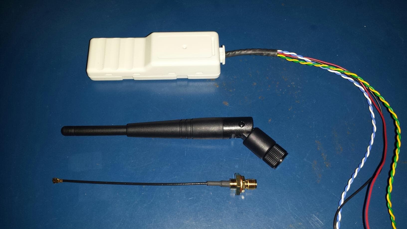
V8NZRB1000152
Jan 22, 2014Wireless bridge
Equipment Class
DTS - Digital Transmission System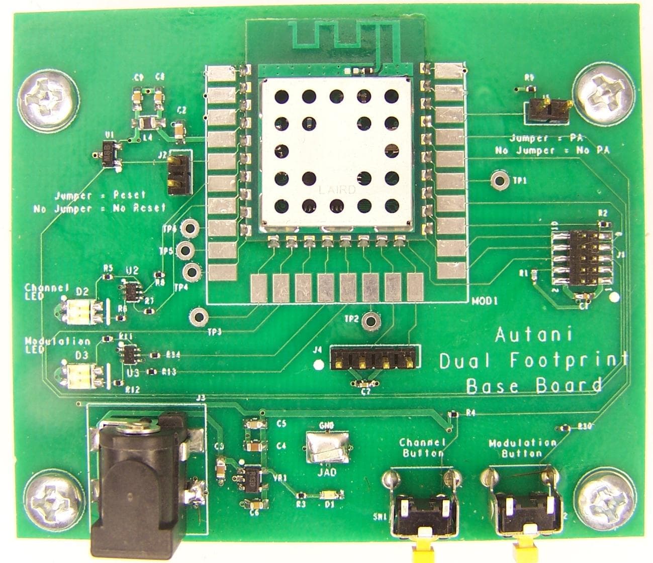
V8NWAT1000142
May 26, 2011Zigbee transceiver
Equipment Class
DTS - Digital Transmission System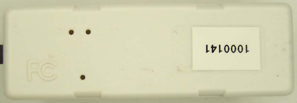
V8NZRB1000141
Feb 17, 2011ZigBee to RS485 Bridge
Equipment Class
DTS - Digital Transmission System