VB6ZM1000Bed remote control
ZINUS(Xiamen) Co., LtdApplication Details
- Equipment Class
- DSC - Part 15 Security/Remote Control Transmitter
- Date of Grant
- Aug 06, 2007
- Application Purpose
- Original Equipment
- Date of Application
- Aug 05, 2007
- Equipment Note
- Bed remote control
- Frequency Range
- 433.00000000 - 433.00000000
- Company
- ZINUS(Xiamen) Co., Ltd
- Country
- China
Documents & Files
Document Text
Text extracted from the exhibit documents filed with the FCC. Open a document above to read the original.
Users Manual
The JCYK-09-3 Remote Handset Use Manual The position of S1-S10 button on the operation panel as following: S1 Save Ysection Zsection Xsection S10 actuator/massage motor selection S2 Up S3 select motor towad left S4 select motor toward right S5 Down S6 Save1 S7 Save2 S8 Save3 S9 Save4 Introduce the use of the JCYK-09-3 remote handset in details: At first, we should divide the LED into three parts:Xsection,Ysection and Zsection.As indicated above. 1. When power on, all the actuators reset to keep the bed in FLAT.(If the RESET couldn’t finished normally, it is possibly the battery supply power to controller. Here, we can take the battery fuse which on the top of the controller case down in order to finish the Reset.) 2. Move the push-button S10 to “B”, then press S3 or S4 to lighten X section of LED. At this moment, Press S2 continuously, the bed HEAD move up: loosen it, the bed HEAD stop moving. Press S5 continuously, the bed HEAD move down: loosen it, the bed HEAD stop moving. When in the process of M1, press the safety switch L1, M1 stop falling. loosen the safety switch,M1 Continue to decline . 3. Move the push-button S10 to “B”, then press S3 or S4 to lighten Y section of LED. At this moment,Press S2 continuously, the bed BUTT move up, loosen it, the bed BUTT stop moving. Press S5 continuously,the bed BUTT move down: loosen it, the bed BUTT stop moving. When in the process of M2, press the safety switch L2, M2 stop falling. loosen the safety switch,M2 keep on stopping . 4. Move the push-button S10 to “B”, then press S3 or S4 to lighten Z section of LED. At this moment,Press S2 continuously, the FEET part move up after flated then drive KNEE up in bend state, loosen S2, the bed stop moving. Press S5 continuously, the KNEE move down to flat bed, then move down bed FEET. loosen S5, bed stop moving. During this course the foreside of bed should keep a certain distance with the ground in order to make sure the bed can work safely and credibility. 5. Move the actuator, when it move to a certain state, press S1,then press S6, the position will be memorized. Wherever the motor move, press S6, the motor move to the position kept just. Press S1 and then press S6 when the motor move to another place,the position of S6 will be changed. When restart ,memory position is the new location. The usage of S7,S8,S9 is same with S6. 6. Move the key-press S10 to “M”,then press S3 or S4 to lighten X section of LED. At this moment,Press S2,the massage motor 1 start vibration,press again, the intensity of motor boost up.Press S5 the intensity of motor weaken. The motor have 5 different intensity. This device complies with part 15 of the FCC Rules. Operation is subject to the following two conditions: (1) This device may not cause harmful interference, and (2) this device must accept any interference received, including interference that may cause undesired operation. Statements from 15.105 and 15.21 NOTE: This equipment has been tested and found to comply with the limits for a Class B digital device, pursuant to part 15 of the FCC Rules. These limits are designed to provide reasonable protection against harmful interference in a residential installation. This equipment generates, uses and can radiate radio frequency energy and, if not installed and used in accordance with the instructions, may cause harmful interference to radio communications. However, there is no guarantee that interference will not occur in a particular installation. If this equipment does cause harmful interference to radio or television reception, which can be determined by turning the equipment off and on, the user is encouraged to try to correct the interference by one or more of the following measures: -Reorient or relocate the receiving antenna. -Increase the separation between the equipment and receiver. -Connect the equipment into an outlet on a circuit different from that to which the receiver is connected. -Consult the dealer or an experienced radio/TV technician for help. Changes or modifications not expressly ap proved by the party responsible for compliance could void the user's authority to operate the equipment authority to operate this equipment.
Block Diagram
Power supply High-frequency transmit circui t MCU Crystal Oscillator Control circuit LED circuit JCYK-09-3 Remote Handset
Operational Description
Power supply High-frequency transmit circui t MCU Crystal Oscillator Control circuit LED circuit JCYK-09-3 Remote Handset The circuit description of The remote controller (model:JC-YK09-3) The remote controller(model:JC-YK09-3) adopts DC3V(2*7th battery) to supply power.When the key is pressed on the remote cotroller ,CPU(U1) will scan the key and read it's value ,then output the singal of the corresponding impulse coding ,meanwhile the LED will light.High frequence surge electricircuit(433.92MHz) is made of high frequence triode transistor Q1,Q2 (3356),SAW(R433.92MHz) and outer electricircuit . The impulse coding signal is modulated to the RF high frequence carrier wave as electromagnetic wave radiate to space .
Parts List/Tune Up Info
LT-7.3.3-01-01 A/0 Component Name Spec/Ratings quantity affirmremark 0603Capacitor2P3 3P1 5P1 6P1 15P1 1022 1041 0603 Resistance20R1 150R1 620R4 2.2K4 10K4 30K1 200K1 10M4 0603Inductance22nH1 33nH2 47nH1 0805 LEDBule light4 dynatronyouzhiR252 80501 85501 SAWR4331 SWITCH3mm1 IC(SOP)PIC16C5051 electronic Capacitor22uF/16V(4×7)1 SOCKET2.54-2P1 JCYK-09-3 BOM(433MHz)
Schematics
C2104 R210K R310K R410K S33S96S109 S54 S88S75 S11S67 S22 RB0 RB1 RB2 Q38050 Q48550 R142.2K R1510K R162.2K LED1R VDD 1 RB5/OS1 2 RB4/OS2 3 RB3/RST 4 RC5/TOCK 5 RC4 6 RC3 7 RC2 8 RC1 9 RC0 10 RB2 11 RB1 12 RB0 13 GND 14 U1PIC16C505 RA0RA1RA2 RA0RA1 RA2 RB0RB1RB2DATA OUT OUT R810M R910M R1010M R172.2K LED2R R182.2K LED3R R192.2K LED4R R202.2K LED5R C1 10uF/16V 12345 J1LED-OUT R13 5.6K R12 5.6K R11 5.6K +3 +3 +3 +3 RB3 R110M S4SW SPST +3 RB3 DC1 +3 1 ANT C103P C4102 C5102 C910P C32PC86P C12X C112P C71.2P C62P SAW1R315 L122NH L247NH L333NH L433NH Q1R25 Q2R25 R5200K R6150R R730K DATA +3
Test Report
Compliance Certification Services (Shenzhen) Inc. Report No: SZ070518B01-RP FCC ID: VB6ZM1000 Date of Issue: July 04, 2007 Note: This report shall not be reproduced except in full, without the written approval of Compliance Certification Services Inc. This document may be altered or revised by Compliance Certification Services Inc. personnel only, and shall be noted in the revision section of the document. Page 1 Total Page: 24 Rev. 00 FCC 47 CFR PART 15 SUBPART C TEST REPORT For Adjustable-Bed Model: M-1-1000,M-2-1000,M-3-1000,M-4-1000,M-5-1000, M-6-1000,M-7-1000 Trade Name: Adjustable-Bed Prepared for ZINUS(XIAMEN) CO., LTD ZINUS BLDG., NO.461-469, HUANZHU ROAD, JIMEI DISTRICT, XIAMEN, CHINA Prepared by COMPLIANCE CERTIFICATION SERVICES (SHENZHEN) INC. (aka COMPLIANCE ENGINEERING SERVICE (CHINA)) NO. 5, JINAO INDUSTRIAL PARK, NO. 35 JUKENG ROAD, DASHUIKENG VILLAGE, GUANLAN TOWN, BAOAN DISTRICT, SHENZHEN, CHINA TEL: 86-755-28055000 FAX: 86-755-28055221 LAB CODE:200577-0 Compliance Certification Services (Shenzhen) Inc. Report No: SZ070518B01-RP FCC ID: VB6ZM1000 Date of Issue: July 04, 2007 Page 2 Rev. 00 TABLE OF CONTENTS 1. TEST RESULT CERTIFICATION............................................................................................. 3 2. EUT DESCRIPTION .................................................................................................................... 4 3. TEST METHODOLOGY ............................................................................................................. 5 3.1 EUT CONFIGURATION.............................................................................................................. 5 3.2 EUT EXERCISE......................................................................................................................... 5 3.3 GENERAL TEST PROCEDURES.................................................................................................. 5 3.4 FCC PART 15.205 RESTRICTED BANDS OF OPERATIONS .............................................. 6 3.5 DESCRIPTION OF TEST MODES................................................................................................. 6 4. INSTRUMENT CALIBRATION................................................................................................. 7 5. FACILITIES AND ACCREDITATIONS ................................................................................... 8 5.1 FACILITIES.............................................................................................................................. 8 5.2 EQUIPMENT............................................................................................................................. 8 5.3 LABORATORY ACCREDITATIONS AND LISTING....................................................................... 8 6. SETUP OF EQUIPMENT UNDER TEST .................................................................................. 9 6.1 SETUP CONFIGURATION OF EUT.............................................................................................. 9 6.2 SUPPORT EQUIPMENT.............................................................................................................. 9 7. FCC PART 15.231 REQUIREMENTS...................................................................................... 10 7.1 20 DB BANDWIDTH .......................................................................................................... 10 7.2 LIMIT OF TRANSMISSION TIME.............................................................................................. 12 7.3 DUTY CYCLE ..................................................................................................................... 14 7.4 RADIATED EMISSIONS........................................................................................................... 18 7.5 POWERLINE CONDUCTED EMISSIONS.................................................................................... 23 Compliance Certification Services (Shenzhen) Inc. Report No: SZ070518B01-RP FCC ID: VB6ZM1000 Date of Issue: July 04, 2007 Page 3 Rev. 00 1. TEST RESULT CERTIFICATION Applicant: ZINUS(XIAMEN) CO., LTD ZINUS BLDG., NO.461-469, HUANZHU ROAD, JIMEI DISTRICT, XIAMEN, CHINA Equipment Under Test: Adjustable-Bed Trade Name: Adjustable-Bed Model: M-1-1000,M-2-1000,M-3-1000,M-4-1000,M-5-1000,M-6-1000, M-7-1000 Date of Test: May 18-July 04,2007 APPLICABLE STANDARDS STANDARD TEST RESULT FCC 47 CFR Part 15 Subpart C No non-compliance noted We hereby certify that: The above equipment was tested by Compliance Certification Services Inc. The test data, data evaluation, test procedures, and equipment configurations shown in this report were made in accordance with the procedures given in ANSI C63.4 and the energy emitted by the sample EUT tested as described in this report is in compliance with conducted and radiated emission limits of FCC Rules Part 15.207, 15.209 and Part 15.231. The test results of this report relate only to the tested sample identified in this report. Approved by: Tested By: Maya You Reviewed By: Clinton Kao/ Manager Eric Wong / Assistant manager COMPLIANCE CERTIFICATION COMPLIANCE CERTIFICATION SERVICES (SHENZHEN) INC. SERVICES (SHENZHEN) INC. Compliance Certification Services (Shenzhen) Inc. Report No: SZ070518B01-RP FCC ID: VB6ZM1000 Date of Issue: July 04, 2007 Page 4 Rev. 00 2. EUT DESCRIPTION Product Adjustable-Bed Trade Name Adjustable-Bed Model Number M-1-1000,M-2-1000,M-3-1000,M-4-1000,M-5-1000,M-6-1000,M-7-1000 Model Difference All the models are identical in electronic level, different model designation applies due to the size of the foam and fabric, and the legs. Power Supply DC3V powered by the battery Frequency Range 433 MHz Antenna Designation PCB Antenna Remark: This submittal(s) (test report) is intended for FCC ID: VB6ZM1000 filing to comply with Section 15.207, 15.209 and 15.231 of the FCC Part 15, Subpart C Rules. Compliance Certification Services (Shenzhen) Inc. Report No: SZ070518…
Text truncated - open the document above for the full version.
Test Setup Photos
Compliance Certification Services (Shenzhen) Inc. Report No: SZ070518B01-RP FCC ID: VB6ZM1000 Date of Issue: July 04, 2007 Page 24 Rev. 00 APPENDIX 1 PHOTOGRAPHS OF TEST SETUP Radiated Emission Set up Photos
Contact Information
Applicant
Steven Park
Test Firm
Compliance Certification Services (Shenzhen) Inc.Clinton Kao
Technical Specifications
| # | Rule Parts | Frequency Range | Power Output |
|---|---|---|---|
| 1 | 15.231 | 433 MHz - 433 MHz | - |
Other Applications from ZINUS(Xiamen) Co., Ltd

VB61101-02
Feb 28, 2011MASSAGE MATTRESS
Equipment Class
CRR - Superregenerative Receiver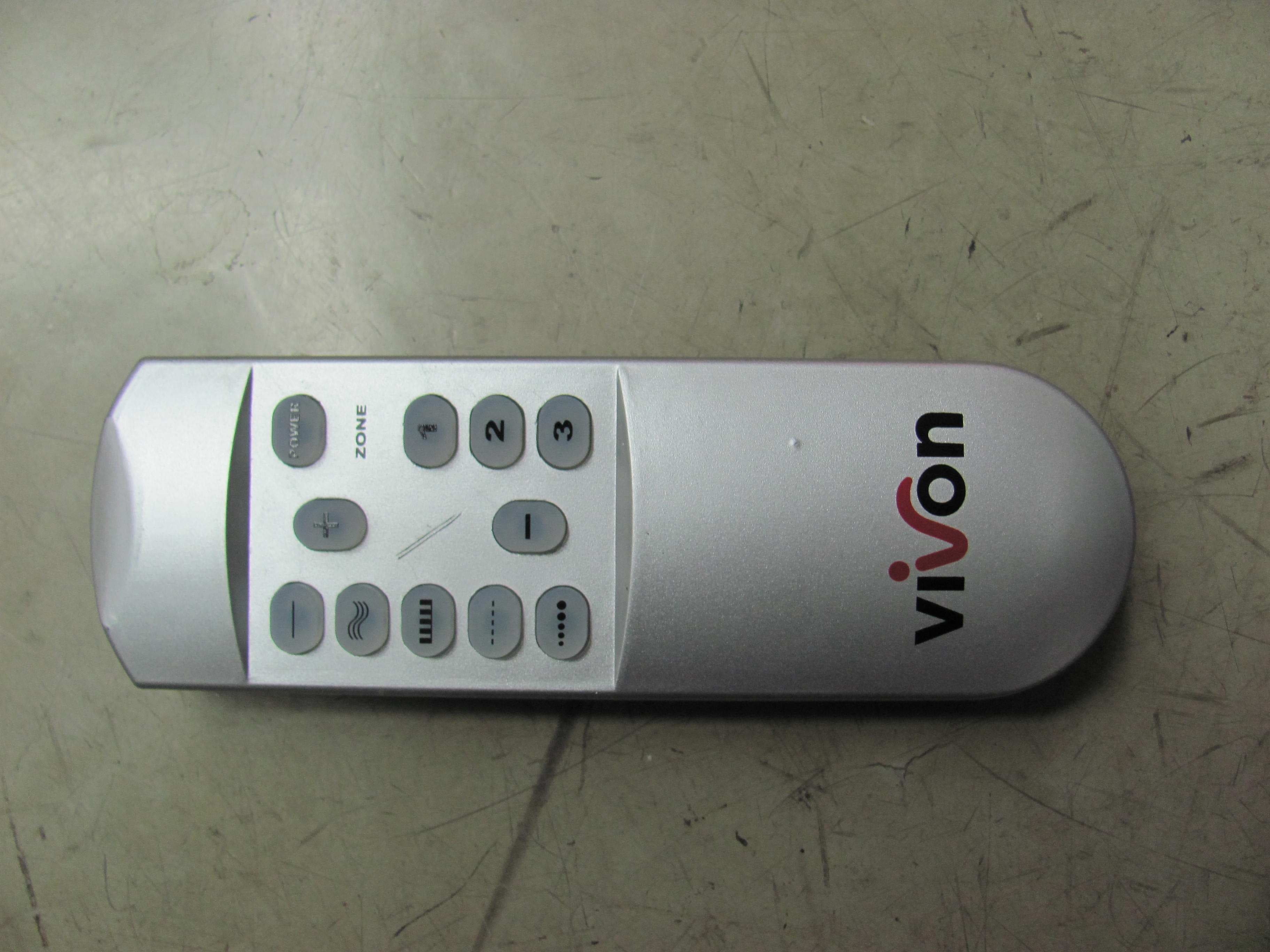
VB61101-01
Feb 28, 2011MASSAGE MATTRESS (remote controller part)
Equipment Class
DSC - Part 15 Security/Remote Control Transmitter