VBA-EF302WFULRemote-control socket outlet
Ningbo EverFlourish Smart Technology Corp.,Ltd
Click to zoom
Application Details
- Equipment Class
- DTS - Digital Transmission System
- Date of Grant
- Aug 11, 2014
- Application Purpose
- Original Equipment
- Date of Application
- Aug 10, 2014
- Equipment Note
- Remote-control socket outlet
- Frequency Range
- 2412.00000000 - 2462.00000000
- Country
- China
Documents & Files
Document Text
Text extracted from the exhibit documents filed with the FCC. Open a document above to read the original.
Users Manual
Instruction Manual for WIFI Smart Socket Type: EMW302WF-UL A. Function 1. This smart socket connects your home wifi network to the connected appliances for easy control of home automation, energy saving and home security. 2. Apps controls any connected electrical appliances via your smart phone or tablet computer. anywhere you go and anytime you like. Applicable both in Apple or Android system. 3. With Alarm function to send an alert message to the registered email or via APP push notification, for the purpose of home security. 4. By refreshing the socket status, you can see your socket’s on/off status from the APP. 5. With push button to control power on/off manually. 6. Timer function setting from the APP is easy and convenient. 7. Possibility to add multiple wifi sockets to suit your need. B. Connection 1. Download the G-homa APP to your smart phone, open the APP and follow the procedure to register your account with valid email address. The system will send you a verification code. 2. Add new device to your smart phone by following the procedure demonstrated in the APP. 3. Once connected, you can either control the appliances via your smart phone or manually. C. LED Flashing Guideline LED Description Flashes slowly (once per second) - Smart socket is searching for the wifi network. - Press and hold the button until the LED flashes quickly (few times per second), socket enters into the connection mode. - Follow the procedure on the APP to activate the new device and enter the wifi password for connection. Flashes quickly (few times per second) - Smart socket is in connection mode. - Follow the instruction “activate a new device” and enter the wifi password for connection. - When connection is successful, the LED will stay ON or OFF, without flashing. Flashes quickly (2-3 seconds interval, 4 flashes each time) - Smart socket is in manual connection mode. - Press and hold the button until LED flashes quickly (few times per second), follow the “Manual Connection” procedure, enter the wifi password for connection. - When connection is successful, the LED stays ON or OFF, without flashing. Flashes 3 times quickly then OFF - Alarm mode is activated. - After activating the device successfully, press and hold the button, LED flashes 3 times quickly, then OFF, the smart socket will send an alert message to your preset email account or by APP push notification. - You can preset your alert message in your APP. On or OFF - Power on /off status indicator. - Connection successful (after connection mode as above). D. Cautions 1. For safety, always switch off your appliances before connecting. 2. For indoor use only. 3. Whenever you change a wifi network, reconnection is required. 4. Do not plug in and out the device continually. Always wait for an interval of 10 seconds AVERTISSEMENTS 1 Pour plus de sécurité, veuillez toujours éteindre vos appareils avant la connexion. 2 Pour une utilisation en intérieur uniquement. 3 Dès que vous modifiez un réseau wifi, la reconnexion est nécessaire. 4 Ne branchez et connectez pas l’appareil fréquemment . Toujours attendre un intervalle de 10 secondes. E. Specifications 1. Power Rating : 125V~, 60Hz, 2. Resistive Load : 1800Wmax. 3. Frequency : 2.4GHz (meets the requirements of IEEE802.11/b/g/n standard) F. Warning This device complies with part 15 of the FCC Rules. Operation is subject to the following two conditions: (1) This device may not cause harmful interference, and (2) this device must accept any interference received, including interference that may cause undesired operation. Le présent appareil est conforme aux CNR d'Industrie Canada applicables aux appareils radio exempts de licence. L'exploitation est autorisée aux deux conditions suivantes : (1) l'appareil ne doit pas produire de brouillage, et (2) l'utilisateur de l'appareil doit accepter tout brouillage radioélectrique subi, même si le brouillage est susceptible d'en compromettre le fonctionnement. Changes or modifications not expressly approved by the party responsible for compliance could void the user's authority to operate the equipment. Limited by local law regulations, version for North America does not have region selection option. This equipment has been tested and found to comply with the limits for a Class B digital device, pursuant to part 15 of the FCC Rules. These limits are designed to provide reasonable protection against harmful interference in a residential installation. This equipment generates uses and can radiate radio frequency energy and, if not installed and used in accordance with the instructions, may cause harmful interference to radio communications. However, there is no guarantee that interference will not occur in a particular installation. If this equipment does cause harmful interference to radio or television reception, which can be determined by turning the equipment off and on, the user is encouraged to try to correct the interference by one or more of the following measures: —Reorient or relocate the receiving antenna. —Increase the separation between the equipment and receiver. —Connect the equipment into an outlet on a circuit different from that to which the receiver is connected. —Consult the dealer or an experienced radio/TV technician for help. To satisfy FCC / IC RF exposure requirements, a separation distance of 20 cm or more should be maintained between the antenna of this device and persons during device operation. To ensure compliance, operations at closer than this distance is not recommended. Les antennes installées doivent être situées de facon à ce que la population ne puisse y être exposée à une distance de moin de 20 cm. Installer les antennes de facon à ce que le personnel ne puisse approcher à 20 cm ou moins de la position centrale de l’ antenne. La FCC des éltats-unis stipule que cet appareil doit être en tout temps éloigné d’au moins 20 cm des personnes pendant son functionnement. G. Manufacturer Everflourish Electrical Co., Ltd. Renjiu Villag…
Text truncated - open the document above for the full version.
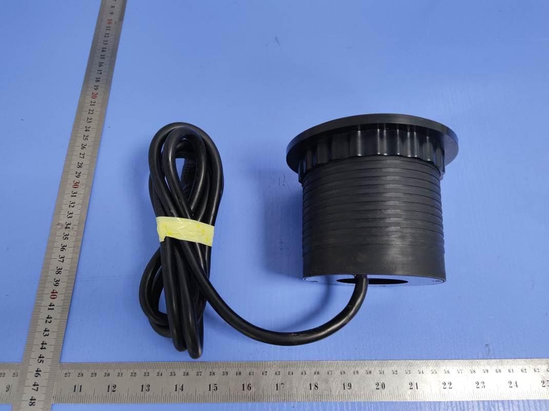
External Photos
FCC ID: VBA-EF302WFUL IC: 7098A-EF302WFUL Page 1 of 3 External Picture FCC ID: VBA-EF302WFUL IC: 7098A-EF302WFUL Page 2 of 3 FCC ID: VBA-EF302WFUL IC: 7098A-EF302WFUL Page 3 of 3
ID Label/Location Info
FCC ID: VBA-EF302WFUL IC: 7098A-EF302WFUL Lable and Location
Internal Photos
FCC ID: VBA-EF302WFUL IC: 7098A-EF302WFUL Page 1 of 4 Internal Picture FCC ID: VBA-EF302WFUL IC: 7098A-EF302WFUL Page 2 of 4 FCC ID: VBA-EF302WFUL IC: 7098A-EF302WFUL Page 3 of 4 FCC ID: VBA-EF302WFUL IC: 7098A-EF302WFUL Page 4 of 4
RF Exposure Info
FCC ID: VBA-EF302WFUL IC: 7098A-EF302WFUL Page 1 of 2 Statement of compliance to Maximum Permissible Exposure (MPE) Applicant : Everflourish Electrical Co., Ltd. Renjiu Village, Wuxiang Town, Yinzhou, Ningbo, 315111, P.R.China Product Name : Remote-control socket outlet Type/Model : EMW302WF-UL According to §2.1091, §2.1093 and §1.1307(b), systems operating under the provisions of this section shall be operated in a manner that ensures that the public is not exposed to radio frequency energy level in excess of the Commission’s guidelines. The S = PG / (4πR²) Where S = power density in mW/cm² P = transmit power in mW G = numeric gain of transmit antenna (numeric gain=Log-1(dB antenna gain/10)) R = distance (cm) The calculations in the table below use the highest gain of antenna for client EUT. These calculations represent worst case in terms of the exposure levels. Frequency band Power Antenna Gain R S Limits (MHz) dBm mW dBi(Numeric) (cm)(mW/cm 2 ) (mW/cm 2 ) 2400 -2483.5 20.12 102.802.01.585 20 0.032 1 Note: 1 mW/cm 2 from 1.310 Table 1 Date of issue: July. 25, 2014 Prepared by: Reviewed by: Wade Zhang (Project Engineer) Daniel Zhao (Reviewer) FCC ID: VBA-EF302WFUL IC: 7098A-EF302WFUL Page 2 of 2 Appendix I Definition below must be outlined in the User Manual: To satisfy FCC RF exposure requirements, a separation distance of 20 cm or more should be maintained between the antenna of this device and persons during device operation. To ensure compliance, operations at closer than this distance is not recommended.
Test Report
FCC ID: VBA-EF302WFUL IC: 7098A-EF302WFUL Page 2 of 58 Description of Test Facility Name: Intertek Testing Services Limited Shanghai Address: Building 86, No. 1198 Qinzhou Rd., North, Shanghai 200233, P.R. China FCC Registration Number: 236597 IC Assigned Code: 2042B-1 Name of contact: Jonny Jing Tel: +86 21 61278271 Fax: +86 21 54262353 FCC ID: VBA-EF302WFUL IC: 7098A-EF302WFUL Page 3 of 58 Content SUMMARY .......................................................................................................................................................... 1 DESCRIPTION OF TEST FACILITY ......................................................................................................................... 2 1. GENERAL INFORMATION ............................................................................................................................ 4 1.1 Applicant Information ..................................................................................................... 4 1.2 Identification of the EUT ................................................................................................ 4 1.3 Technical specification ................................................................................................... 5 1.4 Mode of operation during the test / Test peripherals used .............................................. 5 2. TEST SPECIFICATION .................................................................................................................................. 6 2.1 Instrument list ................................................................................................................. 6 2.2 Test Standard .................................................................................................................. 6 2.3 Test Summary ................................................................................................................. 7 3. MINIMUM 6DB BANDWIDTH ....................................................................................................................... 8 3.1 Limit ................................................................................................................................ 8 3.2 Test Configuration .......................................................................................................... 8 3.3 Test Procedure and test setup .......................................................................................... 8 3.4 Test Protocol ................................................................................................................... 9 4. MAXIMUM PEAK OUTPUT POWER ............................................................................................................. 15 4.1 Test limit ....................................................................................................................... 15 4.2 Test Configuration ........................................................................................................ 15 4.3 Test procedure and test setup ........................................................................................ 15 4.4 Test protocol ................................................................................................................. 16 5. POWER SPECTRUM DENSITY ..................................................................................................................... 17 5.1 Test limit ....................................................................................................................... 17 5.2 Test Configuration ........................................................................................................ 17 5.3 Test procedure and test setup ........................................................................................ 17 5.4 Test Protocol ................................................................................................................. 18 6. RADIATED EMISSION ................................................................................................................................. 24 6.1 Test limit ....................................................................................................................... 24 6.2 Test Configuration ........................................................................................................ 24 6.3 Test procedure and test setup ........................................................................................ 25 6.4 Test protocol ................................................................................................................. 26 7. EMISSION OUTSIDE THE FREQUENCY BAND ............................................................................................. 31 7.1 Limit .............................................................................................................................. 31 7.2 Test Configuration ........................................................................................................ 31 7.3 Test procedure and test setup ........................................................................................ 31 7.4 Test protocol ................................................................................................................. 32 8. POWER LINE CONDUCTED EMISSION ........................................................................................................ 55 8.1 Limit .............................................................................................................................. 55 8.2 Test configuration ......................................................................................................... 55 8.3 Test procedure and test set up ....................................................................................... 56 8.4 Test protocol ................................................................................................................. 57 FCC ID: VBA-…
Text truncated - open the document above for the full version.
Test Setup Photos
FCC ID: VBA-EF302WFUL IC: 7098A-EF302WFUL Page 1 of 3 Test Setup FCC ID: VBA-EF302WFUL IC: 7098A-EF302WFUL Page 2 of 3 1. Radiated Emission Below 1GHz Above 1GHz FCC ID: VBA-EF302WFUL IC: 7098A-EF302WFUL Page 3 of 3 2. Conducted Emission
Contact Information
Applicant
James Zhu(Mr.)
Technical Contact
Intertek Testing Services Limited ShanghaiDaniel Zhao
[email protected]86-21-61278269
Building No.86, 1198 Qinzhou Road(North) · Shanghai · China
Test Firm
Intertek Testing Services Limited ShanghaiJonny Jing
Technical Specifications
| # | Rule Parts | Frequency Range | Power Output |
|---|---|---|---|
| 1 | 15C | 2.41 GHz - 2.46 GHz | 102.80 mW |
Other Applications from Ningbo EverFlourish Smart Technology Corp.,Ltd
VBA-EFEMP410WLUL
Jul 07, 2021Cord extension set
Equipment Class
8CC - Part 18 Consumer Device
VBA-DB400FAC
Apr 22, 2021Wireless Doorbell
Equipment Class
DSC - Part 15 Security/Remote Control Transmitter
VBA-EFEMW202T-1
Jan 01, 2020Remote Control Transmitter
Equipment Class
DSC - Part 15 Security/Remote Control Transmitter
VBA-EF301TK
Oct 29, 2015Remote Control Transmitter
Equipment Class
DSC - Part 15 Security/Remote Control Transmitter
VBA-EF203T1
Jul 06, 2015EMW203T1
Equipment Class
DSC - Part 15 Security/Remote Control Transmitter