VBLMC9090RFID Gun with WLAN and BT
Intelleflex Corporation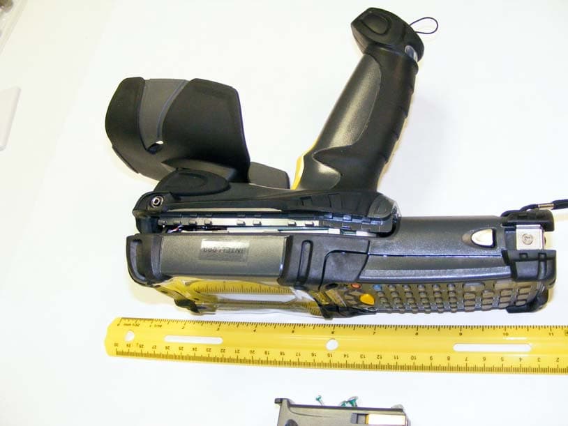
Click to zoom
Application Details
- Equipment Class
- DTS - Digital Transmission System
- Date of Grant
- Oct 06, 2010
- Application Purpose
- Original Equipment
- Date of Application
- Oct 06, 2010
- Equipment Note
- RFID Gun with WLAN and BT
- Frequency Range
- 5745.00000000 - 5830.00000000
- Company
- Intelleflex Corporation
- Country
- United States
Documents & Files
Document Text
Text extracted from the exhibit documents filed with the FCC. Open a document above to read the original.
Users Manual
Motorola reserves the right to make changes to any product to improve reliability, function, or design. Motorola does not assume any product liability arising out of, or in connection with, the application or use of any product, circuit, or application described herein. No license is granted, either expressly or by implication, estoppel, or otherwise under any patent right or patent, covering or relating to any combination, system, apparatus, machine, material, method, or process in which Motorola products might be used. An implied license exists only for equipment, circuits, and subsystems contained in Motorola products. Warranty For the complete Motorola hardware product warranty statement, go to:http://www.motorola.com/enterprisemobility/warranty. Patents This product is covered by one or more patents. For patent information go to: http://www.motorola.com/enterprisemobility/patents. Service Information If you have a problem using the equipment, contact your facility’s Technical or Systems Support. If there is a problem with the equipment, they will contact the Motorola Enterprise Mobility Support at: http://www.motorola.com/enterprisemobility/contactsupport. For the latest version of this guide go to: http://www.motorola.com/enterprisemobility/manuals. Motorola, Inc. One Motorola Plaza Holtsville, New York 11742, USA 1-800-927-9626 http://www.motorola.com/enterprisemobility MOTOROLA and the Stylized M Logo and Symbol and the Symbol logo are registered in the U.S. Patent and Trademark Office. All other product or service names are the property of their respective owners. © Motorola, Inc. 2009 72-132871-01 Revision A — December 2009 Regulatory Guide MC9090-G RFID Microsoft ® CE ® and Windows Mobile ® 6 .1 Regulatory Information This device is approved under the Symbol Technologies brand: Symbol Technologies, Inc., is the Enterprise Mobility business of Motorola, Inc. (“Motorola”). All Motorola/Symbol devices are designed to be compliant with rules and regulations in locations they are sold and will be labeled as required. Local language translations are available at the following website: http://support.symbol.com Any changes or modifications to Motorola/Symbol Technologies equipment, not expressly approved by Motorola/Symbol Technologies, could void the user’s authority to operate the equipment. Radio Devices This device is an approved radio product. Model: MC9090. Model Nos: for Regulatory Certifications: MC9090R1 – Frequency 865.7-867.5 MHz MC9090R6 – Frequency 902-928 MHz Max MC9090R8 – Frequency 869.4-869.65 MHz MC9090R6CN – For China Bluetooth® Wireless Technology This device can contain the following Bluetooth® qualified subsystems: • BTID: B01825 • BTID: B02413 Power Supply Use only a Motorola approved power supply, output rated 12 Vdc and minimum 3.33 A. The power supply is certified to EN60950-1 with SELV outputs. Use of alternative power supply will invalidate any approval given to this device and may be dangerous. Wireless Device Country Approvals Regulatory markings, subject to certification, are applied to the device signifying the radio(s) is/are approved for use in the following countries: United States, Canada and Europe 1,2. Please refer to the Symbol Declaration of Conformity (DoC) for details of other country markings. This is available at http://www2.symbol.com/doc/. Note1: For 2.4GHz or 5GHz Products: Europe includes, Austria, Belgium, Bulgaria, Czech Republic, Cyprus, Denmark, Estonia, Finland, France, Germany, Greece, Hungary, Iceland, Ireland, Italy, Latvia, Liechtenstein, Lithuania, Luxembourg, Malta, Netherlands, Norway, Poland, Portugal, Romania, Slovak Republic, Slovenia, Spain, Sweden, Switzerland and the United Kingdom. Note 2: The use of RFID Devices have varying restrictions of use; please refer to the Motorola/Symbol Declaration of Conformity (DoC) for details. Country Roaming This device incorporates the International Roaming feature (IEEE802.11d) which will ensure the product operates on the correct channels for the particular country of use. Ad-Hoc Operation (802.11a Only) Ad-Hoc operation is limited to Channels 36-48 (5150-5250 MHz). Use of this band is restricted to Indoor Use Only, any other use will make the operation of this device illegal. Frequency of Operation – FCC and IC The use in the UNII (Unlicensed National Information Infrastructure) band 1 5150-5250 MHz band is restricted to Indoor Use Only; any other use will make the operation of this device illegal. The available channels for 802.11 b/g operation in the US are Channels 1 to 11. The range of channels is limited by firmware. Health and Safety Recommendations Ergonomic Recommendations • Reduce or eliminate repetitive motion • Maintain a natural position • Reduce or eliminate excessive force • Keep objects that are used frequently within easy reach • Perform tasks at correct heights • Reduce or eliminate vibration • Reduce or eliminate direct pressure • Provide adjustable workstations • Provide adequate clearance • Provide a suitable working environment • Improve work procedures. Please observe all warning notices with regard to the usage of wireless devices. Potentially Hazardous Atmospheres You are reminded of the need to observe restrictions on the use of radio devices in fuel depots, chemical plants etc. and areas where the air contains chemicals or particles (such as grain, dust, or metal powders) and any other area where you would normally be advised to turn off your vehicle engine. Class 1 Div 2 Product Regulatory Information The following regulatory statements apply only to the Class 1 Div 2 products. The Class 1 Div 2 products are marked UL Listed 3JDT. This equipment is suitable for use in Class 1 Division 2, groups A, B, C, and D or non-hazardous locations only. Use only battery P/N 21-65587-XX or a Motorola approved equivalent. The Class 1 Div 2 approved headset Part No. 200863-001 is the only Class 1 Div 2 approved accessory. WARNING - Explosion Hazard - Do not use headset…
Text truncated - open the document above for the full version.
Cover Letter(s)
tel: 650-726-1263 fax: 650-726-1252 [email protected] Thomas N. Cokenias EMC &Radio Approvals Test & Consulting Services for Commercial, Military, International Compliance P.O. Box 1086 El Granada, CA 94018 email: [email protected] UL CCS 29 September 2010 47173 Benicia Street Fremont, CA 94538 Attention: Application Examiner Re: Request for confidentiality under 0.457 and 0.459 of FCC Rules Applicant: Intelleflex Inc. Equipment: RFID Gun with WLAN and BT FCC ID: VBLMC9090 IC: 7151A-HMR6550 Model No.: HMR-6550 To whom it may concern, On behalf of my client Intelleflex Corporation, this request is being submitted to maintain confidentiality for the following items: Schematic Block diagram Theory of operation Disclosure of these documents to outside parties would give competitors an unfair competitive advantage and could result in considerable financial harm to Intelleflex. If you have questions or need further information please contact the undersigned. Sincerely, T.N. Cokenias Agent for Intelleflex Corporation
Cover Letter(s)
tel: 650-726-1263 fax: 650-726-1252 [email protected] Thomas N. Cokenias EMC &Radio Approvals Test & Consulting Services for Commercial, Military, International Compliance P.O. Box 1086 El Granada, CA 94018 email: [email protected] UL CCS 29 September 2010 47173 Benicia Street, Fremont, CA 94538 Attention: Application Examiner Re: Intelleflex Corporation certification application FCC ID: VBLMC9090 Description: RFID gun with WLAN and BT To whom it may concern, This product is a hand-held RFID gun operating and is classified as a mobile device. Operation is in the following bands: Description Frequency Range, MHz Power output, watts Applicable Rule Section RFID 902.75-927.25 0.863 15C FHSS Bluetooth 2402-2480 0.00096 15C FHSS WLAN 2412-2462 0.092 15C DTS WLAN 5745-5830 0.075 15C DTS WLAN 5180-5240 0.048 15E U-NII 1* WLAN 5745-5805 0.079 15E U-NII 4* *limited by software, no other U-NII bands will be supported at this time. The RFID, Bluetooth, and WLAN radios can operate simultaneously. The Bluetooth radio is imbedded on the main circuit board. Two radio modules are incorporated into the product, however, the entire product has its own FCC ID and the modular approval route is not being employed for this application. Each radio has its own antenna. The WLAN can operate either in the 2.4 GHz band or the 5 GHz band, but not both simultaneously, as it is a single 802.11 module with one TX output. The BT, WLAN, and RFID antennas are all integral to the unit. The following modules are incorporated: Module Description Grantee FCC ID Date of Grant RFID Intelleflex VBLMMR6500 07/12/2010 WLAN Symbol Technologies H9P2121160 01/20/2006 FCC ID: VBLMC9090 is almost identical to a previously granted product, FCC ID: H9PMC9090R6, grants issued 8/14/2006. The only difference is that the original product RFID module is being replaced with the Intelleflex RFID module referenced above. The following modules were used in the original product: Module Description Grantee FCC ID Date of Grant RFID WJ Communications NTTWJMPR7XXX 03/06/2007 WLAN Symbol Technologies H9P2121160 01/20/2006 tel: 650-726-1263 fax: 650-726-1252 [email protected] The RFID gun circuit board, the RFID module connector, the antennas, and the case are all identical to the product certified under FCC ID: H9PMC9090R6. As such, the test reports for the Bluetooth section and the WLAN module of the original product, and the test reports for the Intelleflex module, will be used to support compliance of the RFID gun FCC ID: VBLMC9090. Three certification applications are being submitted: 15C DSSS for RFID and Bluetooth 15C DTS for WLAN at 2.4GHz and 5.8 GHz frequencies 15E U-NII for WLAN at 5.15 and 5.8 GHz frequencies If you have questions or need further information please contact the undersigned. Sincerely, T.N. Cokenias Agent for Intelleflex
External Photos
FCC ID: H9P2121160 SYMBOL TECHNOLOGIES INC 802.11a/b/g RLAN Module 2004 Not to be reproduced without the permission of TÜV Product Service LtdPage 1 of 5 PHOTOGRAPHS OF EQUIPMENT Front View 21-21160-01 FCC ID: H9P2121160 SYMBOL TECHNOLOGIES INC 802.11a/b/g RLAN Module 2004 Not to be reproduced without the Permission of TÜV Product Service LtdPage 2 of 5 PHOTOGRAPHS OF EQUIPMENT Rear View 21-21160-01 FCC ID: H9P2121160 SYMBOL TECHNOLOGIES INC 802.11a/b/g RLAN Module 2004 Not to be reproduced without the Permission of TÜV Product Service LtdPage 3 of 5 PHOTOGRAPHS OF EQUIPMENT Front View 21-21160-02 FCC ID: H9P2121160 SYMBOL TECHNOLOGIES INC 802.11a/b/g RLAN Module 2004 Not to be reproduced without the Permission of TÜV Product Service LtdPage 4 of 5 PHOTOGRAPHS OF EQUIPMENT Rear View 21-21160-02 FCC ID: H9P2121160 SYMBOL TECHNOLOGIES INC 802.11a/b/g RLAN Module 2004 Not to be reproduced without the Permission of TÜV Product Service LtdPage 5 of 5 PHOTOGRAPHS OF EQUIPMENT View Showing Extender Cards & Antennas
External Photos
EXTERNAL VIEW PHOTOGRAPHS Intelleflex Corporation FCC ID: VBLMC9090 IC: 7151A-HMR6550 ID label location
External Photos
External Photographs Applicant: Intelleflex Corporation FCC ID: VBLMMR6500 IC: 7151A-MMR6500
ID Label/Location Info
Intelleflex Corporation FCC ID: VBLMC9090 IC: 7514A-HMR6550 Model No.: HMR-6550 Model No.: HMR-6550 FCC ID: VBLMC9090 IC: 7514A-HMR6550
Internal Photos
FCC ID: H9P2121160 SYMBOL TECHNOLOGIES INC 802.11a/b/g RLAN Module 2004 Not to be reproduced without the permission of TÜV Product Service LtdPage 1 of 4 PHOTOGRAPHS OF EQUIPMENT Internal View 1 21-21160-01 FCC ID: H9P2121160 SYMBOL TECHNOLOGIES INC 802.11a/b/g RLAN Module 2004 Not to be reproduced without the permission of TÜV Product Service LtdPage 2 of 4 PHOTOGRAPHS OF EQUIPMENT Internal View 2 21-21160-01 FCC ID: H9P2121160 SYMBOL TECHNOLOGIES INC 802.11a/b/g RLAN Module 2004 Not to be reproduced without the permission of TÜV Product Service LtdPage 3 of 4 PHOTOGRAPHS OF EQUIPMENT Internal View 3 21-21160-02 FCC ID: H9P2121160 SYMBOL TECHNOLOGIES INC 802.11a/b/g RLAN Module 2004 Not to be reproduced without the permission of TÜV Product Service LtdPage 4 of 4 PHOTOGRAPHS OF EQUIPMENT Internal View 4 21-21160-02
Internal Photos
INTERNAL VIEW PHOTOGRAPHS Intelleflex Corporation FCC ID: VBLMC9090 IC: 7151A-HMR6550
Internal Photos
Internal Photographs Applicant: Intelleflex Corporation FCC ID: VBLMMR6500 IC: 7151A-MMR6500 Top Bottom
RF Exposure Info
RF Exposure for Intelleflex RFID Gun with WLAN and BT FCC ID: VBLMC9090 The referenced product has three transmitters, each with its own internal antenna: Description Frequency Range Pmax, Watts Pmax, dBm Antenna Gain, dBi RFID 902-928 MHz 0.863 29.36 6.0 WiFi at 2.4 GHz 2412-2462 MHz 0.092 19.6 2.0 WiFi at 5GHz 5.15-5.25/ 5.745-5.830GHz 0.079 (U-NII 4) 18.97 3.1 Bluetooth 2402-2480 MHz 0.00096 -0.18 4.0 The product is classified as a mobile device per secion 2.1091 of the Rules. The aggregate RF exposure is calculated by assuming the antennas are equidistant from the observer, a reasonable worst-case condition. The General Population/Uncontrolled Exposure limits are used. For multiple emitters, the powers are summed proportionate to the percentage of power from each transmitter compared to their respective limits. Intelleflex FCC ID: VBLMC9090 902-928 MHz FHSS RadioCalculate mW/cm2 here. Enter frequency in MHz: 2.4 GHz/5 GHz WiFi module Bluetooth Calculation of Limits from 1.1310 Table 1 ControlledUncontrolled 902 MHzWiFiBluetoothAve 6 minAve 30 min mW/cm2 from Table1:0.601.01.0F(MHz)AActual F, MHzOcc, mW/c2 Gen, mW/cm2 0.3-30.5100.0100.0 Max RF Power TX AntennaMPE distanceS, mW/cm@Comment 3.0 - 30.05180.036.0 P, dBmG, dBicmat 20 cm330.0-300551.00.2 300-15009023.00.60 29.366.0021.30.68902 MHz1500-10000055555.01.0 19.602.003.40.03WiFi 2.4GHz 18.973.103.60.03WiFi 5GHz -0.180004.000.40.00Bluetooth Enter P(mW)Equivalent dBm EEnter dBmEquivalent Watts Worst CaseRFx total% MPE at 22cm94%902 MHz 2%WiFi 5 GHz 0%Bluetooth TOTAL96%<100% Basis of Calculations:895.429.5229.52895.4 E^2/3770 = S, mW/cm2 E, V/m = (Pwatts*G gain*30)^.5/d, meters d = ((Pwatts*G*30)/3770*S))^0.5Pwatts*G gain = 10^(PdBm-30+GdBi)/10) S@20cm = 20 lo g (MPE dist/20cm) NOTE: For mobile or fixed location transmitters, minimum separation distance is for FCC compliance is 20 cm, eeven if calculations indicate MPE distance is less Calculations show that the general RF exposure limit is met for worst-case simultaneous transmissions at an MPE distance of greater than 22 cm.
Test Report
tel: 650-726-1263 fax: 650-726-1252 [email protected] Thomas N. Cokenias EMC &Radio Approvals Test & Consulting Services for Commercial, Military, International Compliance P.O. Box 1086 El Granada, CA 94018 email: [email protected] UL CCS 29 September 2010 47173 Benicia Street, Fremont, CA 94538 Attention: Application Examiner Re: Test Report Reference FCC ID: VBLMC9090 Description: RFID gun with WLAN and BT To whom it may concern, This product is a hand-held RFID gun operating and is classified as a mobile device. The following reports are used to support the certification applications for the referenced FCC ID above. Description Frequency Range, MHz Test Report Number/Date Test Report Author RFID 902.75-927.25 10PRO16 Rev.1 07/21/2010 T.N. Cokenias Consulting Bluetooth 2402-2480 0504120256 04/28/2005 PC Test WLAN 2412-2462 F453101 09/09/2004 Sportron International Inc. WLAN 5745-5830 F453101 09/09/2004 Sportron International Inc. WLAN 5180-5240* F453101 09/09/2004 Sportron International Inc. WLAN 5745-5805* F453101 09/09/2004 Sportron International Inc. *limited by software, no other U-NII bands will be supported at this time. The RFID report is for the Intelleflex module, which connects to the RFID gun internal 6 dBi antenna. The Bluetooth antenna is an on-board chip antenna. The BT antenna has a maximum gain of 4 dBi. The WLAN has diversity RX antennas, one TX port, and is imbedded in the RFID gun. The maximum gain of the WLAN antenna is 2 dBi at 2.4 GHz, and 3.1 dBi at 5 GHz. If you have questions or need further information please contact the undersigned. Sincerely, T.N. Cokenias Agent for Intelleflex
Test Report
FCC ID: H9P2121160 Issued on Sep. 09, 2004 Report No.: F453101 SPORTON International Inc. TEL : 886-2-2696-2468 FAX : 886-2-2696-2255 FCC TEST REPORT CATEGORY : Module for Portable Host PRODUCT NAME : 802.11a/b/g RLAN module FCC ID. : H9P2121160 FILING TYPE : Certification – Class II Permissive Change BRAND NAME : SYMBOL TYPE NO. : 21-21160 MODEL OF HOST : MC3090 (with 11a/b/g module) APPLICANT : SYMBOL Technologies, Inc. One Symbol Plaza Holtsville, New York, 11742-1300 U.S.A MANUFACTURER : Universal Scientific Industrial Co., Ltd. 141, Lane 351, Taiping Road, Sec.1, Tsao Yuen, Nan-Tou, Taiwan, R.O.C. ISSUED BY : SPORTON INTERNATIONAL INC. 6F, No. 106, Sec. 1, Hsin Tai Wu Rd., His Chih, Taipei Hsien, Taiwan, R.O.C. Statements: This test report is only for the 802.11b/g part of the product, test result of 802.11a is in another separate test report. The test result in this report refers exclusively to the presented test model / sample. Without written approval of SPORTON, the test report shall not be reproduced except in full. Certificate or Test Report could not be used by the applicant to claim the product endorsement by CNLA, NVLAP or any agency of U.S. government. The test equipment used to perform the test are calibrated and traceable to NML/ROC or NIST/USA. Dr. Alan Lane Vice General Manager Sporton International Inc. Lab Code: 200079-0 FCC ID: H9P2121160 Issued on Sep. 09, 2004 Report No.: F453101 SPORTON International Inc. Page No. : i TEL : 886-2-2696-2468 Issued Date : Sep. 09, 2004 FAX : 886-2-2696-2255 Table of Contents History of this test report....................................................................................................................................ii 1. General Description of Equipment under Test.............................................................................................3 1.1. Applicant..........................................................................................................................................................................................3 1.2. Manufacturer ...................................................................................................................................................................................3 1.3. Basic Description of Equipment under Test ....................................................................................................................................3 1.4. Features of Equipment under Test..................................................................................................................................................3 1.5. Table for Carrier Frequencies .........................................................................................................................................................4 2. Test Configuration of the Equipment under Test.........................................................................................5 2.1. Description of the Test ....................................................................................................................................................................5 2.2. Frequency Range Investigated .......................................................................................................................................................5 2.3. Test Modes......................................................................................................................................................................................5 2.4. Description of Test Supporting Units...............................................................................................................................................6 2.5. Connection Diagram of Test System ..............................................................................................................................................6 2.6. Test Software ..................................................................................................................................................................................7 3. Test Location and Standards .........................................................................................................................8 3.1. Test Location...................................................................................................................................................................................8 3.2. Test Conditions ...............................................................................................................................................................................8 3.3. Standards for Methods of Measurement .........................................................................................................................................8 3.4. DoC Statement................................................................................................................................................................................8 4. List of Measurements......................................................................................................................................9 4.1. Summary of the Test Results ..........................................................................................................................................................9 5. Test Result .....................................................................................................................................................10 5.1. Test of Spectrum Bandwidth of a Direct Sequence Spread Spectrum System (6 dB Bandwidth) .............................................10 5.2. Test of Maximum Peak Output Power ..........................................................................................................................................15 5.3. Test of Peak Power Spectral Density..........................................................................................…
Text truncated - open the document above for the full version.
Contact Information
Applicant
Dean Kawaguchi(RFID Systems Architect)
Technical Contact
T.N. Cokenias ConsultingThomas Cokenias
[email protected]6507261263
El Granada, California · United States
Non-Technical Contact
T.N. Cokenias ConsultingThomas Cokenias
[email protected]6507261263
Test Firm
Compliance Certification ServicesThu Chan
Technical Specifications
| # | Rule Parts | Frequency Range | Power Output |
|---|---|---|---|
| 2 | 15C | 5.75 GHz - 5.83 GHz | 75.00 mW |
Other Applications from Intelleflex Corporation
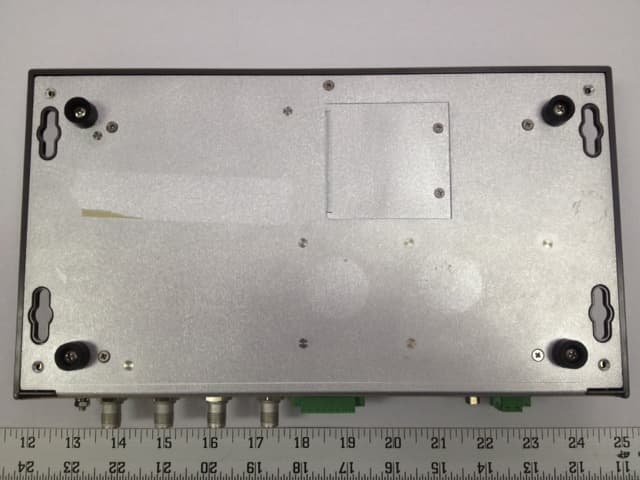
VBLCMR-6100
Jun 01, 2012RFID Readerr with Integrated GSM and GPS module
Equipment Class
DSS - Part 15 Spread Spectrum Transmitter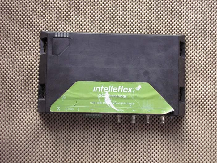
VBLFMR-6000
Dec 20, 2010RFID Reader
Equipment Class
DSS - Part 15 Spread Spectrum Transmitter
VBLMMR6500
Jul 11, 2010RFID Reader Module
Equipment Class
DSS - Part 15 Spread Spectrum Transmitter