VEIMANDDANT130FM Modulator
CENEC CORP.
Click to zoom
Application Details
- Equipment Class
- DXX - Part 15 Low Power Communication Device Transmitter
- Date of Grant
- Jul 04, 2010
- Application Purpose
- Original Equipment
- Date of Application
- Jul 04, 2010
- Equipment Note
- FM Modulator
- Frequency Range
- 88.10000000 - 107.90000000
- Company
- CENEC CORP.
- Country
- Taiwan
Documents & Files
Document Text
Text extracted from the exhibit documents filed with the FCC. Open a document above to read the original.
Users Manual
IMPORTANT NOTICE n Before operating the unit, please read these instructions carefully. n Retain the manual for future reference. n You are advised to follow the instructions carefully when operating the unit. n Do not use any chemical solvents, cleaning agents or corrosive detergents to clean dirt off the surface of the screen. By doing so, you may cause irreversible damage to the surface of the TFT screen. To clean off dirt or fingerprints, we recommend using a soft, damp, lens cleaning cloth. n Using spare parts from another manufacturer may cause permanent damage to the unit. n When operating the display unit, avoid touching or pressing the LCD glass panel. n Excessive force may cause irreparable damage to the LCD screen. n Some states restrict the use of video screens and televisions in vehicles. In the interest of safety, this monitor shouldnever be installed where it will be visible, directly or indirectly, by the operator of the motor vehicle. n Lock the LCD screen in the fully closed position when it is not in use. AHDM7/ 1 MAIN SPECIFICATIONS n DISPLAY: 7.0" wide screen TFT LCD active matrix n RESOLUTION: 480 (W) X 234 (H) x 3 (R.G.B.) n DOT PITCH: 0.107mm (W) X 0.370mm (H) n VIEWING ANGLE: 65/50/65/65( Top / Bottom / Left / Right ) n BRIGHTNESS: 400 cd/m2 n CONTRAST RATIO: 400:1 n POWER SOURCE: DC 12V ( Negative Ground) n POWER CONSUMPTION: 20W ( Max.) n OPERATING TEMPERATURE: 0~60(32~140) n STORAGE TEMPERATURE: -20~70(-4~158) n DIMENSIONS: 185mm x 60mm x 155 mm (W x D x H) MAIN FEATURES n HEADREST 7.016:9 WIDE SCREEN TFT-LCD MONITOR n BUILT IN DVD PLAYER n BUILT IN WIRELESS HEADPHONE IR TRANSMITTER n 1 AUDIO/VIDEO INPUT n FULL FUNCTION WIRELESS REMOTE CONTROL n (OSD) ON SCREEN DISPLAY FOR CONTROL OF PICTURE QUALITY AND FUNCTIONS n FULL BAND WIRELESS FM MODULATOR WITH 6 PRESETS MEMORY. AHDM7/ 2 AHDM7/ 3 DVD PLAYER Supports DVD, VCD, AUDIO CD, and MP3. MONITOR 7.0" wide screen TFT LCD active matrix STANDARD ACCESSORIES PACKAGE CONTENTS n Remote control (AAA x 2 batteries) n Operating manual n A/V input cable OPTIONAL ACCESSORIES Single Channel Wireless IR Headphones AE21 Dual Channel Wireless IR Headphones AE22 CONTROLS & CONNECTORS n POWER button- Press to turn the selected on/off. n SOURCE button- Press to toggle between desired sources. n MENU button- Press menu button to activate and select OSD features. n UP/DOWN buttons - Adjustment buttons. n IR sensor- IR sensor for remote control. n IR transmitter- transmits audio to wireless headphones. n DVD player- Plays DVD, VCD, AUDIO CD, and MP3. MONITOR FUNCTION DESCRIPTIONS DRIVER button PASSENGER button Press these buttons to select which monitor you would like to control with the remote control. POWER button Press this button to turn on the selected monitor, press again to turn off the monitor. SOURCE button Press SOURCE button to toggle between sources on the selected monitor. VOLUME UP button VOLUME DOWN button Use these buttons to raise and lower the volume level of the audio output. MUTE button Press to mute the audio, press the button again to restore sound to the previous audio level. PIC MENU button Press this button to activate the OSD menu screen. CTRL LEFT button CTRL RIGHT button Use these buttons to change the function/ value of the monitor settings. AHDM7/ 4 REMOTE CONTROL OPERATION AHDM7/ 5 DVD FUNCTION DESCRIPTIONS NUMBER buttons Direct access for CD tracks, DVD chapters, and password setting. PBC/MENU button Toggles available subtitles when playing VCD 2.0, or shortcut to DVD selection title menu. TITLE button Certain DVDs come with title selections. For such cases, the TITLE button allows the user to select desired title. SUBTITLE button Toggles the displayed subtitles if available on your selection. BACK button Allows the user to search in a backward direction. UP button Moves the selection or cursor up. FWD button Allows the user to search in a forward direction. LEFT button Moves the selection or cursor left. PLAY / PAUSE button Starts playback or starts a feature while a disc is loaded in the disc player or pauses media playback. RIGHT button Moves the selection or cursor right. PREVIOUS button Returns to the previous chapter or track. DOWN button Moves the selection or cursor down. NEXT button Advances to the next chapter or track. STOP button Media playback will be halted. ENTER button Press this button to confirm selection. A-B button Allows the user to repeat play of a DVD or CD from point A to point B. Press button once to set point A once again to set point B. REPEAT button Allows the user to repeat play various positions of a DVD, CD or MP3.(Track/Chapter/All) SET UP button Allows the user to select the DVD player's options. (General, Audio, Video, Preference, Password, Exit Setup) DISPLAY button Press to display current media information. ZOOM button Allows the user to zoom in or zoom out the image, press the "LEFT/RIGHT/UP/DOWN" buttons to move the zoomed image in the direction of the remaining portion of the image. AHDM7/ 6 MONITOR OPERATION Adjust the monitor to a comfortable viewing angle free from glare or bright ambient light. c Press the POWERbutton on the unit or remote to turn on the monitor. c Press the SOURCEbutton to select viewing source. c Press the MENU buttonto activate the OSD menu shown on the LCD screen. c Press the MENU buttonagain to select the adjustment item, press the "+" or "- " button to adjust the desired function/value. c The DIMMERfeature dims the backlight to reduce glare during operation in reduced lighting conditions. AHDM7/ 7 c The BRIGHTNESS adjustment controls the intensity of the backlight. c The CONTRAST adjustment controls the black level ratio. c The COLOR adjustment controls the balance of blue, yellow, and red. c The TINT adjustment controls the intensity of blue, yellow, and red. c The FM PRESETS toggles between 6 preset FM frequencies set for source broadcast, Press > to scroll stored presets. Hold < for 3 seconds to store desired preset. c The RESET sele…
Text truncated - open the document above for the full version.
External Photos
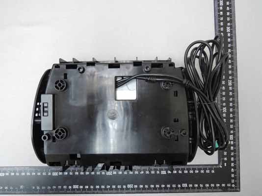
ETC Report No.:10-05-RBF-073 Sheet 1 of 6 Sheets FCC ID.: VEIMANDDANT130 Rev. No 2.0 CONSTRUCTED PHOTOS of EUT 1. Total View of EUT 2. Front View of EUT ETC Report No.:10-05-RBF-073 Sheet 2 of 6 Sheets FCC ID.: VEIMANDDANT130 Rev. No 2.0 CONSTRUCTED PHOTOS of EUT 3. Side View of EUT 4. Rear View of EUT ETC Report No.:10-05-RBF-073 Sheet 3 of 6 Sheets FCC ID.: VEIMANDDANT130 Rev. No 2.0 CONSTRUCTED PHOTOS of EUT 5. Side View of EUT 6. Bottom View of EUT ETC Report No.:10-05-RBF-073 Sheet 4 of 6 Sheets FCC ID.: VEIMANDDANT130 Rev. No 2.0 CONSTRUCTED PHOTOS of EUT 7. ETC Report No.:10-05-RBF-073 Sheet 5 of 6 Sheets FCC ID.: VEIMANDDANT130 Rev. No 2.0 CONSTRUCTED PHOTOS of EUT 8. Internal View of EUT ETC Report No.:10-05-RBF-073 Sheet 6 of 6 Sheets FCC ID.: VEIMANDDANT130 Rev. No 2.0 CONSTRUCTED PHOTOS of EUT 9. Component View of PCB 10. Component View of PCB
ID Label/Location Info
910805 1 LABEL 48mm 16.5mm Model:ANT130 FCC ID: VEIMANDDANT130 This device complies with Part 15 of the FCC Rules. Operation is subject to the following two conditions: (1) this device may not cause harmful interference, and (2) this device must accept any interference received, including interference that may cause undesired operation.
Internal Photos
ETC Report No.:10-05-RBF-073 Sheet 5 of 6 Sheets FCC ID.: VEIMANDDANT130 Rev. No 2.0 CONSTRUCTED PHOTOS of EUT 8. Internal View of EUT ETC Report No.:10-05-RBF-073 Sheet 6 of 6 Sheets FCC ID.: VEIMANDDANT130 Rev. No 2.0 CONSTRUCTED PHOTOS of EUT 9. Component View of PCB 10. Component View of PCB
Test Report
Rev. No 2.0 FCC Part 15 Subpart C TEST REPORT of E.U.T. : FM Modulator FCC ID. : VEIMANDDANT130 MODEL : ANT130 Working Frequency : 88.1~107.9 MHz for APPLICANT : CENEC Corp. ADDRESS : 10F., No.63, Sec. 1, Sanmin Rd., Banciao City, Taipei County 220, Taiwan(R.O.C.) Test Performed by ELECTRONICS TESTING CENTER, TAIWAN NO. 34. LIN 5. DINGFU TSUEN, LINKOU SHIANG TAIPEI COUNTY, TAIWAN, 24442, R.O.C. http://www.etc.org.tw ; e-mail : [email protected] Tel:(02)26023052 Fax:(02)26010910 Report Number: 10-05-RBF-073 ETC Report No.:10-05-RBF-073 FCC ID.: VEIMANDDANT130 Rev. No 2.0 TEST REPORT CERTIFICATION Applicant : CENEC Corp. 10F., No.63, Sec. 1, Sanmin Rd., Banciao City, Taipei County 220, Taiwan(R.O.C.) Manufacturer : CENEC Corp. 10F., No.63, Sec. 1, Sanmin Rd., Banciao City, Taipei County 220, Taiwan(R.O.C.) Description of EUT : a) Type of EUT : FM Modulator b) Trade Name : CENEC CORP. c) Model No : ANT130 d) Working Frequency : 88.1~107.9 MHz e) Power Supply : Power from host DVD monitor (DC 12V) Regulation Applied : FCC Rules and Regulations Part 15 Subpart C (2009) I HEREBY CERTIFY THAT; The data shown in this report were made in accordance with the procedures given in ANSI C63.4 and the energy emitted by the device was founded to be within the limits applicable. I assume full responsibility for accuracy and completeness of these data. Issued Date : May 28, 2010 Test Engineer : ( Vincent Chang, Engineer ) Test Engineer : (Charles Wang, Supervisor ) Approve & Authorized Signer : Will Yauo, Manager EMC Dept. II of ELECTRONICS TESTING CENTER, TAIWAN ETC Report No.:10-05-RBF-073 FCC ID.: VEIMANDDANT130 Rev. No 2.0 Table of Contents 1. GENERAL INFORMATION..................................................................................................1 1.1 Product Description..............................................................................................................1 1.2 Test Methodology.................................................................................................................1 1.3 Test Facility ...................................................................................................................1 2. DEFINITION AND LIMITS....................................................................................................2 2.1 Definition ...................................................................................................................2 2.2 Restricted Bands of Operation.............................................................................................2 2.3 Limitation ...................................................................................................................2 2.4 Labeling Requirement..........................................................................................................3 2.5 User Information ...................................................................................................................3 3. SYSTEM TEST CONFIGURATION.....................................................................................4 3.1 Justification ...................................................................................................................4 3.2 Devices for Tested System...................................................................................................4 4 RADIATED EMISSION MEASUREMENT..........................................................................5 4.1 Applicable Standard..............................................................................................................5 4.2 Measurement Procedure.......................................................................................................5 4.3 Measuring Instrument...........................................................................................................7 4.4 Test Data ...................................................................................................................8 4.5 Field Strength Calculation..................................................................................................11 4.6 Radiated Measurement Photos..........................................................................................12 5 CONDUCTED EMISSION MEASUREMENT...................................................................13 5.1 Standard Applicable............................................................................................................13 6 ANTENNA REQUIREMENT...............................................................................................14 6.1 Standard Applicable............................................................................................................14 6.2 Antenna Construction.........................................................................................................14 7 EMISSION BAND MEASUREMENT..................................................................................15 7.1 Standard Applicable............................................................................................................15 7.2 Measurement Procedure.....................................................................................................15 7.3 Measurement Equipment....................................................................................................15 7.4 Measurement Data..............................................................................................................15 ETC Report No.:10-05-RBF-073 Sheet 1 of 20 Sheets FCC ID.: VEIMANDDANT130 Rev. No 2.0 1. GENERAL INFORMATION 1.1 Product Description a) Type of EUT : FM Modulator b) Trade Name : CENEC CORP. c) Model No. : ANT130 d) Frequency Modulation : 88.1~107.9 MHz e) Power Supply : Power from host DVD monitor (DC 12V) 1.2 Test Methodology Both conducted and radiated testing was performed according to the procedures in chapter 13 of ANSI C63.4 (2003) The EUT was operated in its normal operating mode for the purp…
Text truncated - open the document above for the full version.
Test Setup Photos
ETC Report No.:10-05-RBF-073 Sheet 12 of 20 Sheets FCC ID.: VEIMANDDANT130 Rev. No 2.0 4.6 Radiated Measurement Photos
Contact Information
Applicant
James Lee(PM Manager)
Test Firm
Taiwan Testing and Certification CenterAnderson Ku
Technical Specifications
| # | Rule Parts | Frequency Range | Power Output |
|---|---|---|---|
| 1 | 15C | 88.1 MHz - 107.9 MHz | - |
Other Applications from CENEC CORP.
VEIMD9
Jan 25, 2016Headrest monitor with DVD-player
Equipment Class
DXX - Part 15 Low Power Communication Device Transmitter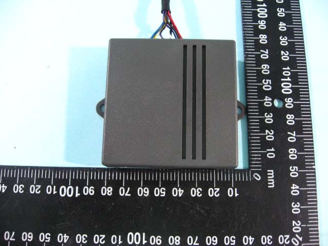
VEIMANDDACCM85
Jan 31, 2010FM Transmitter
Equipment Class
DXX - Part 15 Low Power Communication Device Transmitter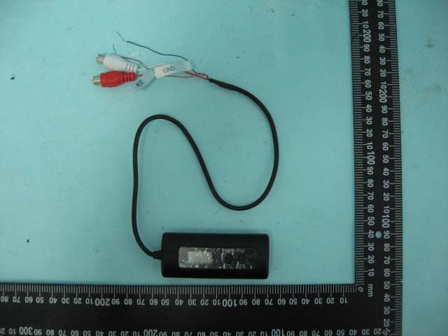
VEIANT-188
Jul 10, 2007FM Transmitter
Equipment Class
DXX - Part 15 Low Power Communication Device Transmitter