VEYCN3200R1Dual Band Routing Modem
Vislink Technologies, Inc.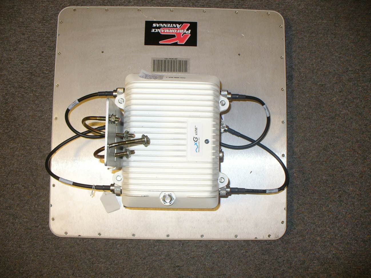
Click to zoom
Application Details
- Equipment Class
- DTS - Digital Transmission System
- Date of Grant
- Sep 29, 2014
- Application Purpose
- Original Equipment
- Date of Application
- Sep 29, 2014
- Equipment Note
- Dual Band Routing Modem
- Frequency Range
- 904.20000000 - 925.80000000
- Company
- Vislink Technologies, Inc.
- Country
- United States
Documents & Files
Document Text
Text extracted from the exhibit documents filed with the FCC. Open a document above to read the original.
Users Manual
Certification Exhibit FCC ID: VEYCN3200R1 FCC Rule Part: 15.247 ACS Project: 14-2096 Manufacturer: xG Technology, Inc. Model: CN3200 Manual 3998 FAU Blvd. Suite 310 Boca Raton, FL 33431 Tel: 561-961-5585 Fax: 561-961-5587 Dual Band Routing Modem - Quick Start Guide - G7603 - Release 0.1 2 Dual Band Routing Modem - Quick Start Guide - G7603 - Release 0.1 Product features and specifications are subject to change without prior notice. xG® and xMax® are registered trademarks of xG Technology, Inc. All other trademarks used herein are property of their respective owners. For the latest product documentation and software updates, please refer to our Web site at www.xGTechnology.com/support xG Technology, Inc. 240 South Pineapple Avenue, Suite 701 Sarasota, FL 34236 (941) 953-9035 www.xGTechnology.com 3 Dual Band Routing Modem - Quick Start Guide - G7603 - Release 0.1 Table of Contents Introduction ............................................................................................................... 5 About this Product ...................................................................................................... 5 About this Book .......................................................................................................... 5 Hardware Overview .................................................................................................... 5 Powering the CN3200 Modem .................................................................................... 6 Important Safety and Installation Notices ................................................................... 7 FCC Part 15 Requirement ............................................................................................ 7 Hazard ........................................................................................................................ 7 FCC Compliance .......................................................................................................... 7 RF Exposure ................................................................................................................ 8 Connecting the CN3200 Dual Band Routing Modem to the xMax Network ................. 9 Connecting Wireless Devices to the xMax Network .................................................. 10 Wired Internet Connectivity and Setting Up a WiFi Hotspot ...................................... 11 Wired Internet Connectivity ..................................................................................... 11 Technical Specifications ............................................................................................ 12 Warranty .................................................................................................................. 13 Limited Warranty ...................................................................................................... 13 SCOPE OF THE WARRANTY .............................................................................................................. 13 ADDITIONAL PROVISIONS OF THE WARRANTY ............................................................................... 14 OBTAINING SERVICE AND SUPPORT UNDER WARRANTY ............................................................... 15 EXCLUSIVITY OF THE WARRANTY .................................................................................................... 15 4 Dual Band Routing Modem - Quick Start Guide - G7603 - Release 0.1 THIS PAGE INTENTIONALLY LEFT BLANK 5 Dual Band Routing Modem - Quick Start Guide - G7603 - Release 0.1 The CN3200 Dual Band Routing Modem is a ruggedized subscriber device. It is waterproof and made to handle wide temperature ranges. While primarily designed for use in fixed locations, it may also be used in vehicular applications. It enables any Internet-ready device to connect to the xMax network, when paired with a WiFi access point either wirelessly or through a wired Ethernet connection. This manual provides basic instructions for installation and configuration of the CN3200 Modem. It also describes how to connect to the xMax Network and then connect Internet-enabled wireless devices to the xMax Network. The CN3200 Dual Band Routing Modem is a self-contained IEEE 802.11b/g access point which provides any device connected to its Ethernet port access to the xMAX network. When paired with a WiFi hotspot it provides access to the xMAX network to WiFi enabled devices. The CN3200 Modem is totally protected against dust and moisture. IMPORTANT: The CN3200 is professionally installed. xMax Panel Antenna and Cables (4) 2.4 GHz Panel Antenna with Mounting Bracket and Cable PoE++ Power Supply and AC Power Cord Weatherproof Ethernet Kit Ferrite Beads (6) Installation Bracket and Hardware 6 Dual Band Routing Modem - Quick Start Guide - G7603 - Release 0.1 The CN3200 Modem is a Power-over-Ethernet (PoE+) device. The IEEE 802.3at PoE+ standard enables transmission of both data and the power to operate a device over a single Cat5/5e/6 cable connection. The CN3200 Modem REQUIRES a PoE++ adaptor, as supplied. The device will NOT operate with a low-power PoE switch or adaptor. Wireless Router or PC 110-240 VAC, 50-60 Hz PoE++ Power Supply TO CN3200 Modem ETHERNET DATA POWER plus DATA 7 Dual Band Routing Modem - Quick Start Guide - G7603 - Release 0.1 These notices apply to the CN3200 Dual Band Routing Modem. Be sure to read, understand and follow these instructions. Heed all warnings. Only use accessories and attachments specified by xG Technology. Keep a copy of these instructions for future reference. The CN1300 xMax 2.4 GHz Access Point MUST only be installed by a professional installer. It is the responsibility of the installer to adjust the transmit power level to ensure that the output power plus antenna gain does not cause the device to exceed FCC Part 15 output power regulations. ous situation, which if not avoided, could result in death or serious injury. All antennas MUST either be loca…
Text truncated - open the document above for the full version.
Cover Letter(s)
5015 B. U. Bowman Dr. Buford, GA 30518 September 25, 2014 ACS TCB 5015 B.U. Bowman Drive Buford, GA 30518 Re: FCC ID: VEYCN3200R1 To Whom It May Concern: The following application is submitted on behalf of our client, xG Technology, Inc., for evaluation of their CN3200 for certification under FCC Part 15.247. The model CN3200 consists of 900 MHz 2TX/4RX MIMO transceiver which uses the same RF board as the FCC ID: VEYXAP1. The CN3200 uses a 11.3 dBi panel antenna which is cross-polarized for the TX side. The unit also includes a 2.4 GHz WLAN module (VEYCN3200W1). The CN3200 was evaluated for all available modulations at the maximum allowable duty cycle. To comply to the unintentional radiated emissions requirements the unit uses a total of eight (8) ferrites on the Ethernet cables. Four (4) ferrites (FAIR-RITE 0443164251) are used on the shielded Ethernet cable from the EUT to the POE adapter. The additional four (4) ferrites (FAIR-RITE 0443164251) are used on the Ethernet cable from the POE adapter to the remote laptop computer. The FCC ID: VEYCN3200R1 was tested as described above to the aforementioned rules and was found to be in compliance. Sincerely, Sam Wismer Vice President, Technology Advanced Compliance Solutions, Inc.
Cover Letter(s)
7771 West Oakland Park Blvd • Suite 231 • Sunrise , FL 33351 • 954.572.0395 • 954.972.0397 (F) • www.xgtechnology.com hl CONFIDENTIALITY REQUEST Federal Communications Commission Date: Equipment Authorization Branch 7435 Oakland Mills Road Columbia, MD 21046 Gentlemen: xG Technology, Inc. respectfully requests confidentiality of certain materials provided with the submission of the CN3200 under FCC ID: VEYCN3200R1 in accordance with 47 CFR 0.457(d) and 47 CFR 0.459. The confidentiality request applies to the block diagram, schematics, theory of operation contained in this filing and included in the following files. 14-2096 – Block Diagram.pdf 14-2096 – Schematics.pdf 14-2096 – Theory of Operation.pdf The CN3200 has been developed at considerable effort and expense by xG Technology, Inc. These items are considered as Trade Secrets and therefore public access to the proprietary material could possibly result in duplication of equipment that could severely damage the company's business advantage. I appreciate your assistance in this matter. Sincerely, ________________________________________ Signature: Name: Roger Branton Date: 9/10/2014 Title: Chief Financial Officer
Cover Letter(s)
7771 West Oakland Park Blvd • Suite 231 • Sunrise , FL 33351 • 954.572.0395 • 954.972.0397 (F) • www.xgtechnology.com hl Date: 9-10-2014 Federal Communications Commission Equipment Authorization Branch 7435 Oakland Mills Road Columbia, MD 21046 Dear Sir or Madam: I hereby appoint Sam Wismer at Advanced Compliance Solutions, Inc. to act as our agent in the preparation of an application for equipment authorization of FCC ID: VEYCN3200R1 to the FCC Rules and Regulations. I certify that all exhibits contained within this filing properly describe the device or system for which authorization is sought. I further certify that appropriate arrangements have been made to assure that production units of this equipment bearing the name and FCC IDENTIFIER listed in this application will continue to comply with the Commission's requirements. I further certify by signature below that no party (per 47 CFR 1.2002(b)) to the application is subject to a denial of Federal benefits, including FCC benefits, pursuant to Section 5301 of the Anti-Drug Abuse Act of 1988, 21 U.S.C. 853(a). This appointment also includes the authority to complete FCC Form 731 on our behalf and sign the application as an authorized agent. Sincerely, _____________________________________ (Signature) Name: Roger Branton Title: Chief Financial Officer
External Photos
Certification Exhibit FCC ID: VEYCN3200R1 FCC Rule Part: 15.247 ACS Project: 14-2096 Manufacturer: xG Technology, Inc. Model: CN3200 External Photos 3998 FAU Blvd. Suite 310 Boca Raton, FL 33431 Tel: 561-961-5585 Fax: 561-961-5587 Model: CN3200W1 FCC ID: VEYCN3200R1 Figure 1: Front View ACS Project: 14-2096 Advanced Compliance Solutions Page 2 Model: CN3200W1 FCC ID: VEYCN3200R1 Figure 2: Rear View ACS Project: 14-2096 Advanced Compliance Solutions Page 3 Model: CN3200W1 FCC ID: VEYCN3200R1 Figure 3: Top View ACS Project: 14-2096 Advanced Compliance Solutions Page 4 Model: CN3200W1 FCC ID: VEYCN3200R1 Figure 4: Bottom View ACS Project: 14-2096 Advanced Compliance Solutions Page 5 Model: CN3200W1 FCC ID: VEYCN3200R1 Figure 5: Side View ACS Project: 14-2096 Advanced Compliance Solutions Page 6 Model: CN3200W1 FCC ID: VEYCN3200R1 Figure 6: Side View ACS Project: 14-2096 Advanced Compliance Solutions Page 7 Model: CN3200W1 FCC ID: VEYCN3200R1 Figure 7: Front View with Antenna ACS Project: 14-2096 Advanced Compliance Solutions Page 8 Model: CN3200W1 FCC ID: VEYCN3200R1 Figure 8: Top View with Antenna ACS Project: 14-2096 Advanced Compliance Solutions Page 9 Model: CN3200W1 FCC ID: VEYCN3200R1 Figure 9: Bottom View with Antenna ACS Project: 14-2096 Advanced Compliance Solutions Page 10 Model: CN3200W1 FCC ID: VEYCN3200R1 Figure 10: Side View with Antenna ACS Project: 14-2096 Advanced Compliance Solutions Page 11 Model: CN3200W1 FCC ID: VEYCN3200R1 Figure 11: Side View with Antenna ACS Project: 14-2096 Advanced Compliance Solutions Page 12
ID Label/Location Info
Certification Exhibit FCC ID: VEYCN3200R1 FCC Rule Part: 15.247 ACS Project: 14-2096 Manufacturer: xG Technology, Inc. Model: CN3200 Label Information 3998 FAU Blvd. Suite 310 Boca Raton, FL 33431 Tel: 561-961-5585 Fax: 561-961-5587 Company xG Technology, Inc CN3200 Housing label Location: Underside of Housing CN3200 Housing inset size: 2 ½ x 1 ½ CN3200 CN3200 Top-side Company xG Technology, Inc Product Family: xMAX FCC Label for: CN3200 Dual Band Routing Modem Font Size 6 FCC ID: VEYCN3200R1 Contains FCC ID: VEYCN3200W1 THIS DEVICE COMPLIES WITH PART 15 OF THE FCC RULES. OPERATION IS SUBJECT TO THE FOLLOWING TWO CONDITIONS. (1)THIS DEVICE MAY NOT CAUSE HARMFUL INTERFERENCE, AND (2) THIS DEVICE MUST ACCEPT ANY INTERFERNCE RECEIVED, INCLUDING INTERFERENCE THAT MAY CAUSE UNDESIRED OPERATION. . 2.5” 1.5”
Internal Photos
Certification Exhibit FCC ID: VEYCN3200R1 FCC Rule Part: 15.247 ACS Project: 14-2096 Manufacturer: xG Technology, Inc. Model: CN3200 In ternal Photos 3998 FAU Blvd. Suite 310 Boca Raton, FL 33431 Tel: 561-961-5585 Fax: 561-961-5587 Model: CN3200W1 FCC ID: VEYCN3200R1 Figure 1: Wi-Fi Board Top View ACS Project: 14-2096 Advanced Compliance Solutions Page 2 Model: CN3200W1 FCC ID: VEYCN3200R1 Figure 2: Wi-Fi Board Bottom View ACS Project: 14-2096 Advanced Compliance Solutions Page 3 Model: CN3200W1 FCC ID: VEYCN3200R1 Figure 3: DPM Bottom ACS Project: 14-2096 Advanced Compliance Solutions Page 4 Model: CN3200W1 FCC ID: VEYCN3200R1 Figure 4: DPM Top ACS Project: 14-2096 Advanced Compliance Solutions Page 5 Model: CN3200W1 FCC ID: VEYCN3200R1 Figure 5: Main Board Shield Figure 6: Main Board Top ACS Project: 14-2096 Advanced Compliance Solutions Page 6 Model: CN3200W1 FCC ID: VEYCN3200R1 Figure 7: Main Board Top (Close-up) Figure 8: Main-DPM Board Bottom ACS Project: 14-2096 Advanced Compliance Solutions Page 7 Model: CN3200W1 FCC ID: VEYCN3200R1 Figure 9: Main-DPM Board Bottom (Close-up) ACS Project: 14-2096 Advanced Compliance Solutions Page 8 Model: CN3200W1 FCC ID: VEYCN3200R1 Figure 10: POE Extractor Bottom Figure 11: POE Extractor Top ACS Project: 14-2096 Advanced Compliance Solutions Page 9 Model: CN3200W1 FCC ID: VEYCN3200R1 Figure 12: Router Board Bottom ACS Project: 14-2096 Advanced Compliance Solutions Page 10 Model: CN3200W1 FCC ID: VEYCN3200R1 Figure 13: Router Board Top Figure 14: Router Wi-Fi Board ACS Project: 14-2096 Advanced Compliance Solutions Page 11 Model: CN3200W1 FCC ID: VEYCN3200R1 Figure 15: Internal Assembly ACS Project: 14-2096 Advanced Compliance Solutions Page 12
RF Exposure Info
Certification Exhibit FCC ID: VEYCN3200R1 FCC Rule Part: 15.247 ACS Project: 14-2096 Manufacturer: xG Technology, Inc. Model: CN3200 RF Exposure 3998 FAU Blvd. Suite 310 Boca Raton, FL 33431 Tel: 561-961-5585 Fax: 561-961-5587 Model: CN3200 FCC ID: VEYCN3200R1 General Information: Applicant: xG Technology, Inc. ACS Project: 14-2096 Device Category: Fixed Environment: General Population/Uncontrolled Exposure Technical Information: Antenna Type: Panel Antenna (4 RX x 2 TX) Antenna Gain: 11.3 dBi Maximum Transmitter Conducted Power: 24.23 dBm, 264.85 mW Maximum System EIRP: 35.53 dBm, 3572.728 mW Exposure Conditions: Greater than 25 centimeters MPE Calculation The Power Density (mW/cm 2 ) is calculated as follows: S = 2 4R PG π Where: S = power density (in appropriate units, e.g. mW/cm2) P = power input to the antenna (in appropriate units, e.g., mW) G = power gain of the antenna in the direction of interest relative to an isotropic radiator R = distance to the center of radiation of the antenna (appropriate units, e.g., cm) The CN3200 uses a MIMO (4 RX x 2 TX) 11.3 dBi Panel Antenna. The directional gain of the array is calculated per FCC KDB Publication No. 662911 D01 Multiple Transmitter Output v02r01. Directional Gain = G ANT + Array Gain Array Gain = 10*log(N ANT /N SS ) dB Where, G ANT = Antenna Gain N ANT = number of transmit antennas and N SS = number of spatial streams. (Assume N SS = 1 unless you have specific information to the contrary.) For the panel antenna configuration, the TX antennas are cross-polarized. Therefore, the directional gain is the individual gain of the antenna: Directional Gain = 11.3 dBi The MPE calculations for the CN3200 operating single-handedly using the directional gain are provided below: MPE Calculator for Mobile Equipment Limits for General Population/Uncontrolled Exposure* 90024.230.60264.8511.3 13.490 250.455 Power Density (mW/cm^2) Distance (cm) Transmit Frequency (MHz) Radio Power (dBm) Power Density Limit (mW/Cm2) Radio Power (mW) Antenna Gain (dBi) Antenna Gain (mW eq.) ACS Project: 14-2096 Advanced Compliance Solutions Page 2 Model: CN3200 FCC ID: VEYCN3200R1 Installation Guidelines The installation manual should contain text similar to the following advising how to install the equipment to maintain compliance with the FCC RF exposure requirements: Summation of Power Densities The xG Technology CN3200 (FCC ID: VEYCN3200R1) host device also includes a WLAN CN3200W1 module (FCC ID: VEYCN3200W1). The WLAN uses a 15 dBi panel antenna and can transmit simultaneously with the 900 MHz radio within the CN3200. The MPE calculations for the WLAN radio are provided below. Table 1: Wi-Fi model CN3200W1 MPE Calculations MPE Calculator for Mobile Equipment Limits for General Population/Uncontrolled Exposure* 243715.211.0033.191531.623 200.209 243715.211.0033.191531.623 250.134 Power Density (mW/cm^2) Distance (cm) Transmit Frequency (MHz) Radio Power (dBm) Power Density Limit (mW/Cm2) Radio Power (mW) Antenna Gain (dBi) Antenna Gain (mW eq.) Note: The CN3200W1 stand-alone meets the RF exposure requirements at a distance of 20 cm with the 15 dBi antenna. When the CN3200W1 is installed inside of the CN3200 host device, a minimum separation distance of 25 cm is needed for the CN3200 system to meet the RF Exposure requirements. The 900 MHz and 2.4 GHz radios can operate simultaneously. Therefore, the maximum RF exposure is determined by the summation of the MPE ratios. The limits is such that the total MPE ratio is less or equal to 1.0 The maximum MPE ratio is calculated as such, using the power densities values at 25 cm: 900 MHz xMax and 2.4 GHz WLAN Operating Simultaneously: 900 MHz xMax MPE Ratio + 2.4 GHz WLAN MPE Ratio (0.455/0.6) + (0.134/1) = (0.758 + 0.134) = 0.892 < 1 RF Exposure In accordance with FCC requirements of human exposure to radio frequency fields, the radiating element shall be installed such that a minimum separation distance of 25 centimeters will be maintained. Conclusion This device complies with the MPE requirements by providing adequate separation between the device, any radiating structure and the general population. ACS Project: 14-2096 Advanced Compliance Solutions Page 3
Test Report
Certification Test Report FCC ID: VEYCN3200R1 FCC Rule Part: 15.247 ACS Report Number: 14-2096 .W03.1A Manufacturer: xG Technology, Inc Model: CN3200 Test Begin Date: January 17, 2014 Test End Date: September 24, 2014 Report Issue Date: September, 24 2014 FOR THE SCOPE OF ACCREDITATION UNDER CERTIFICATE NUMBER AT-1533 This report must not be used by the client to claim product certification, approval, or endorsement by ACLASS, ANSI, or any agency of the Federal Government. Reviewed by: Thierry Jean-Charles EMC Engineer Advanced Compliance Solutions, Inc. This test report shall not be reproduced except in full. This report may be reproduced in part with prior written consent of ACS, Inc. The results contained in this report are representative of the sample(s) submitted for evaluation. This report contains 113 pages 3998 FAU Blvd. Suite 310 Boca Raton, FL 33431 Tel: 561-961-5585 Fax: 561-961-5587 TABLE OF CONTENTS 1 GENERAL ...................................................................................................... 3 1.1 Purpose .............................................................................................................................................. 3 1.2 Product Description .......................................................................................................................... 3 1.3 Test Methodology and Considerations ........................................................................................... 3 2 TEST FACILITIES .......................................................................................... 4 2.1 Location ............................................................................................................................................. 4 2.2 Laboratory Accreditations/Recognitions/Certifications ............................................................... 4 2.3 Radiated & Conducted Emissions Test Site Description .............................................................. 5 3 APPLICABLE STANDARD REFERENCES................................................... 7 4 LIST OF TEST EQUIPMENT .......................................................................... 8 5 SUPPORT EQUIPMENT ................................................................................ 9 6 EQUIPMENT UNDER TEST SETUP BLOCK DIAGRAM ............................ 10 7 SUMMARY OF TESTS ................................................................................. 11 7.1 Antenna Requirement – FCC: Section 15.203 ..............................................................................11 7.2 6 dB Bandwidth - FCC: Section 15.247(a)(2) / Occupied Bandwidth (OBW) ............................12 7.3 Maximum Conducted Output Power - FCC Section 15.247(b)(3) ..............................................44 7.4 Band-Edge Compliance and Spurious Emissions-FCC 15.247(d) ...............................................46 7.5 Power Spectral Density - FCC Section 15.247(e) ..........................................................................92 7.6 Duty Cycle ......................................................................................................................................109 7.7 Power Line Conducted Emissions – FCC: Section 15.207 .........................................................110 8 CONCLUSION ............................................................................................ 113 Model: CN3200 FCC ID: VEYCN3200R1 1 GENERAL 1.1 Purpose The purpose of this report is to demonstrate compliance with Part 15 Subpart C of the FCC’s Code of Federal Regulations 1.2 Product Description The CN3200 Dual Band Routing Modem is an all-IP, high-capacity and high-performance wireless access point. It is waterproof and made to handle wide temperature ranges. The CN3200 Modem is designed for installation in fixed locations such as towers and buildings. The EUT is a 2 TX x 4 RX transceiver which operates in the ISM band of 902 MHz - 928 MHz and also includes a 2.4 GHz WLAN module model CN3200W1 (FCC ID: VEYCN3200W1). Technical Information: Band of Operation: 904.2 MHz - 925.8 MHz Number of Channels: 16 Modulation Format: BPSK, QPSK, 16-QAM, 64-QAM Antenna Type/Gain: Panel Antenna, 11.3 dBi Operating Voltage: 48 VDC through POE Injector Manufacturer Information: xG Technology, Inc 7771 West Oakland Park Blvd, Suite 231 Sunrise, FL 33351 Test Sample Serial Number(s): VMTRP19140034 Test Sample Condition: The unit was in good operating condition with no physical damages. 1.3 Test Methodology and Considerations The EUT was evaluated for radiated and RF conducted and power line conducted emissions for all modulation formats. The CN3200 uses the exact RF board as the xG Technology model xAP (FCC ID: VEYXAPR1). Therefore, RF conducted data from the evaluation of the FCC ID: VEYXAPR1 that is representative of the CN3200 is reused in this document from the test report 14-2006.W04.1B. The radiated emissions measurements were performed on the EUT cabinet with 50 Ohm terminations at the TX antenna ports. Compliance within the restricted bands was also investigated via the RF conducted method per the KDB Publication No. 558074 D01 DTS Meas Guidance v03r02. The EUT was also evaluated for radiated emissions for inter-modulation products generated by the co-located 900 MHz and 2.4 GHz radios when they are transmitting at the same time. All intermodulation products were found compliant to the limits of Section 15.209. The RF output power and spurious emissions measurements were collected with a test software power setting of 21. The RF conducted measurements were performed directly at each of the TX antenna ports through suitable attenuation. The maximum RF output power was calculated using the methodologies described in KDB Publication No. 662911 D01 Multiple Transmitter Output v02r01. The TX antennas are cross-polarized in the panel antenna. Therefore, the directional gain was determined to be equal to the gain at each antenna port = 11…
Text truncated - open the document above for the full version.
Test Setup Photos
Certification Exhibit FCC ID: VEYCN3200R1 FCC Rule Part: 15.247 ACS Project: 14-2096 Manufacturer: xG Technology, Inc. Model: CN3200 Test Setup Photos 3998 FAU Blvd. Suite 310 Boca Raton, FL 33431 Tel: 561-961-5585 Fax: 561-961-5587 Model: CN3200 FCC ID: VEYCN3200R1 Figure 1: Radiated Emissions – Front View ACS Project: 14-2096 Advanced Compliance Solutions Page 2 Model: CN3200 FCC ID: VEYCN3200R1 Figure 2: Radiated Emissions – Back View ACS Project: 14-2096 Advanced Compliance Solutions Page 3 Model: CN3200 FCC ID: VEYCN3200R1 Figure 3: RF Conducted Emissions ACS Project: 14-2096 Advanced Compliance Solutions Page 4 Model: CN3200 FCC ID: VEYCN3200R1 Figure 4: Power Line Conducted Emissions – Front View ACS Project: 14-2096 Advanced Compliance Solutions Page 5 Model: CN3200 FCC ID: VEYCN3200R1 Figure 5: Power Line Conducted Emissions – Side View ACS Project: 14-2096 Advanced Compliance Solutions Page 6
Contact Information
Applicant
Michael C Bond(CFO)
Test Firm
TUV SUD America, Inc.Sam Wismer
Technical Specifications
| # | Rule Parts | Frequency Range | Power Output |
|---|---|---|---|
| 1 | 15C | 904.2 MHz - 925.8 MHz | 265.00 mW |
Other Applications from Vislink Technologies, Inc.
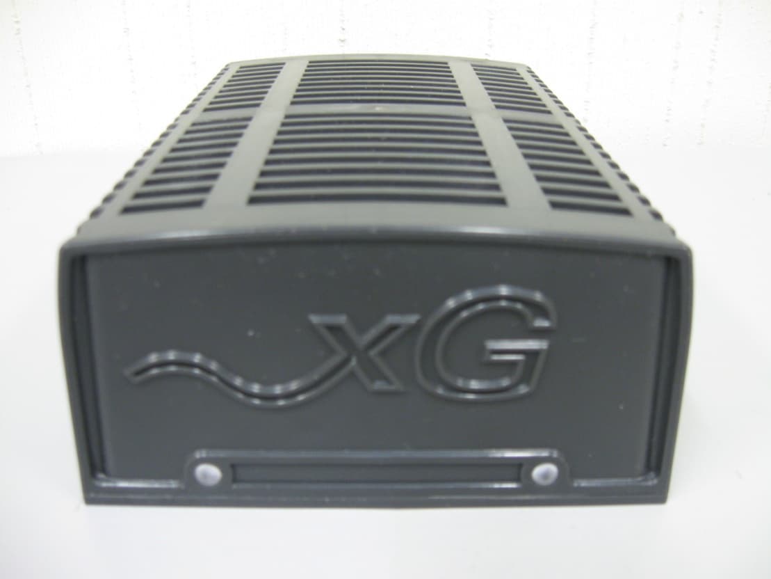
VEYXMODR2
Sep 03, 2013xMod
Equipment Class
DTS - Digital Transmission System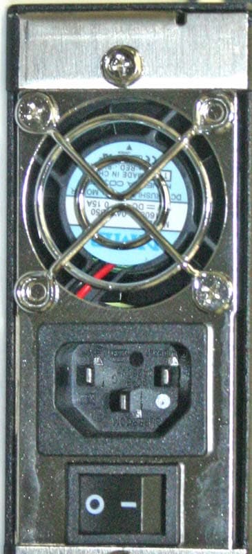
VEYXMAXBTS100
Dec 16, 2007xMax VOIP Base Transceiver Station
Equipment Class
DTS - Digital Transmission System