VEYXMODR2xMod
Vislink Technologies, Inc.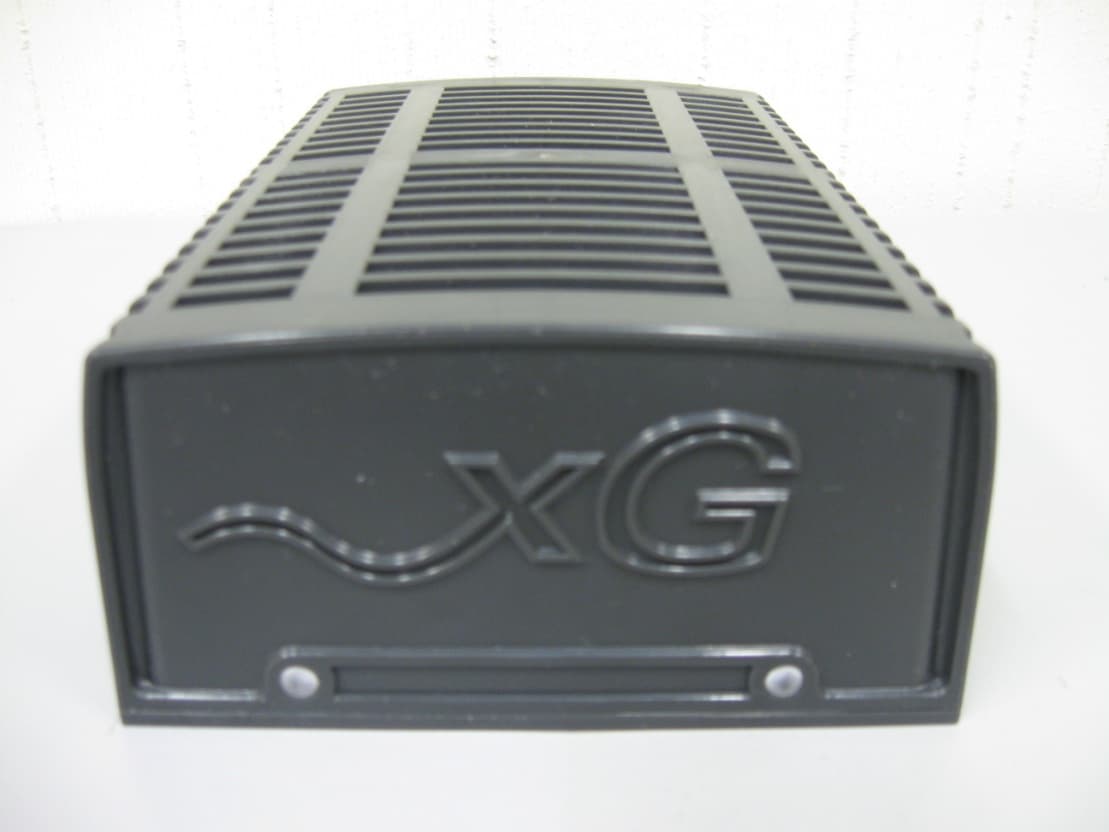
Click to zoom
Application Details
- Equipment Class
- DTS - Digital Transmission System
- Date of Grant
- Sep 03, 2013
- Application Purpose
- Original Equipment
- Date of Application
- Sep 03, 2013
- Equipment Note
- xMod
- Frequency Range
- 904.20000000 - 925.80000000
- Company
- Vislink Technologies, Inc.
- Country
- United States
Documents & Files
Document Text
Text extracted from the exhibit documents filed with the FCC. Open a document above to read the original.
Users Manual
3998 FAU Blvd. Suite 310 Boca Raton, FL 33431 Tel: 561-961-5585 Fax: 561-961-5587 Certification Exhibit FCC ID: VEYXMODR2 FCC Rule Part: 15.247 ACS Project: 13-2112 Manufacturer: xG Technology, Inc. Model: xMod User Manual xMod Quick Start Guide 2 xG Technology xMod 2.5 Quick Start Guide Table of Contents Introduction........................................................................................................................................... 3 Box Contents.......................................................................................................................................... 3 Hardware Overview.............................................................................................................................. 3 Configuring the xMod for the First Time........................................................................................... 4 Connecting the xMod device to the xMax Network........................................................................... 4 Connecting user devices to the xMax Network.................................................................................. 4 Safety Notices........................................................................................................................................ 6 Electrical Safety Information............................................................................................................... 6 Compliance............................................................................................................................................ 6 RF Exposure.......................................................................................................................................... 7 Warranty............................................................................................................................................... 7 3 xG Technology xMod 2.5 Quick Start Guide Introduction The xMax xMod device is a wired/wireless bridge between xMax and 802.11 protocols. It allows WiFi enabled devices to connect to an xMax network. This manual provides basic operations instructions for the unit. Box Contents The xMod device is shipped with the following items. xMod Device Ac Adaptor Ethernet Cable USB to USB Micro Cable Hardware Overview The xMod device is a self contained 802.11b/g access point and xMax modem. The xMod 802.11 AP is a full featured hot spot allowing connection by up to 5 users. The xMod has Ethernet, USB and Power connectors. 4 xG Technology xMod 2.5 Quick Start Guide The xMod device has 2 LEDs, a status LED and Power LED. The definition of the LED states is listed below. Power LED Status LED Solid Green- Device Powered Solid Green- Registered with system Flashing Green- Registering Device Fault Orange- No xMax signal Red- Device Fault Configuring the xMod for the First Time • Connect the power cord to the AC adaptor. • Plug the AC adaptor into the barrel connector on the xMod device. • Using the Ethernet cable provided connect a Laptop or Desktop to the Ethernet connection on the xMod device. • Plug the AC adaptor into a wall power outlet. The power LED will green • Configure the web browser on the laptop/desktop for a static IP address 169.254.80.100. Within 2 minutes of xMod power the Ethernet port will be enabled. • Direct the browser to IP address 169.254.80.101. A user name/password screen should appear. The default user name is admin with no password. • On the configuration screen, change the password. • Continue to the wireless settings page. Change the SSID and WEP key as desired. • Hit update and the xMod will reset. • After 2 minutes and assuming the xMod device is in range of the xMax network, the xMod device will be functional and provide 802.11 connections to wireless devices. Connecting the xMod device to the xMax Network This step assumes that the xMod device has been configured for the first time. • Power the xMod by connecting the AC power adaptor. • Observe the status LED. • If after 2 minutes the status LED is steady green lit, then the xMod is connected to the xMax network and ready to begin operation. • If the Status indicator is Orange check to see if you are within range of an operating xMax network Connecting user devices to the xMax Network 5 xG Technology xMod 2.5 Quick Start Guide Using a WiFi enabled device, configured for DHCP operation, connect to the SSID and password that was configured in the previous step. When connected you are able to begin data operations like web browsing. Alternately configure a PC or tablet interface for DHCP operation. Connect Ethernet or USB cable to the xMod and begin data operations. 6 xG Technology xMod 2.5 Quick Start Guide Safety Notices • Read, follow, and keep these instructions. • Heed all warnings. • Only use attachments/accessories specified by the manufacturer. • Warning: Electrical Safety Information • Compliance is required with respect to voltage, frequency, and current requirements indicated on the manufacturer’s label. • Connection to a different power source than those specified may result in improper operation, damage to the equipment or pose a fire hazard if the limitations are not followed. • There are no operator serviceable parts inside this equipment. Service should be provided only by a qualified service technician. • This equipment is provided with a detachable power cord which has an integral safety ground wire intended for connection to a grounded safety outlet. • Do not substitute the power cord with one that is not the provided approved type. Never use an adapter plug to connect to a 2-wire outlet as this will defeat the continuity of the grounding wire. • The equipment requires the use of the ground wire as a part of the safety certification, modification or misuse can provide a shock hazard that can result in serious injury or death. • Contact a qualified electrician or the manufacturer if there are questions about the installation prior to connecti…
Text truncated - open the document above for the full version.
Cover Letter(s)
5015 B. U. Bowman Dr. Buford, GA 30518 August 20, 2013 ACS TCB 5015 B.U. Bowman Drive Buford, GA 30518 Re: FCC ID: VEYXMODR2 To Whom It May Concern: The following application is submitted on behalf of our client, xG Technology, Inc., for evaluation of their model xMod for certification under FCC Part 15.247. The model xMod (FCC ID: VEYXMODR2) is a wireless/wired bridge enabling 802.11b/g and Ethernet supporting devices to connect to the xG Technology xMax network. The unit consists of the 900 MHz xMax radio and 802.11b/g WLAN module (FCC ID: VEYXMODR1W1). The unit was evaluated for all available modulations at the maximum allowable duty cycle. The unit was also evaluated for co-location of both 900 MHz xMax and 2.4 GHz WLAN radios when transmitting at the same time. All inter-modulation products were found to be compliant to the limits of 15.209. The FCC ID: VEYXMODR2 was tested in full to the requirements of the aforementioned rules and was found to be in compliance. Sincerely, Sam Wismer Vice President, Technology Advanced Compliance Solutions, Inc.
External Photos
3998 FAU Blvd. Suite 310 Boca Raton, FL 33431 Tel: 561-961-5585 Fax: 561-961-5587 Certification Exhibit FCC ID: VEYXMODR2 FCC Rule Part: 15.247 ACS Project: 13-2112 Manufacturer: xG Technology, Inc. Model: xMod External Photos Model: xMod FCC ID: VEYXMODR2 Figure 1: EUT – Top and Front View ACS Project: 13-2112 Advanced Compliance Solutions Page 2 Model: xMod FCC ID: VEYXMODR2 Figure 2: EUT – Top and Rear View ACS Project: 13-2112 Advanced Compliance Solutions Page 3 Model: xMod FCC ID: VEYXMODR2 Figure 3: EUT - Bottom View ACS Project: 13-2112 Advanced Compliance Solutions Page 4 Model: xMod FCC ID: VEYXMODR2 Figure 4: EUT - Left Side View ACS Project: 13-2112 Advanced Compliance Solutions Page 5 Model: xMod FCC ID: VEYXMODR2 Figure 5: EUT - Right Side View ACS Project: 13-2112 Advanced Compliance Solutions Page 6
ID Label/Location Info
3998 FAU Blvd. Suite 310 Boca Raton, FL 33431 Tel: 561-961-5585 Fax: 561-961-5587 Certification Exhibit FCC ID: VEYXMODR2 FCC Rule Part: 15.247 ACS Project: 13-2112 Manufacturer: xG Technology, Inc. Model: xMod Label Information Company xG Technology, Inc Product Family: xMax FCC Label for: xMod (Subscriber Unit) Font Size 6 1.25” 3.0” FCC ID: VEYXMODR2 Contains FCC ID: VEYXMODR1W1 THIS DEVICE COMPLIES WITH PART 15 OF THE FCC RULES. OPERATION IS SUBJECT TO THE FOLLOWING TWO CONDITIONS. (1)THIS DEVICE MAY NOT CAUSE HARMFUL INTERFERENCE, AND (2) THIS DEVICE MUST ACCEPT ANY INTERFERNCE RECEIVED, INCLUDING INTERFERENCE THAT MAY CAUSE UNDESIRED Company: xG Technology, Inc. Product: xMOD FCC Label Location: Bottom Flat Surface center FCC Label Size: 3.0” x 1.25”
Internal Photos
3998 FAU Blvd. Suite 310 Boca Raton, FL 33431 Tel: 561-961-5585 Fax: 561-961-5587 Certification Exhibit FCC ID: VEYXMODR2 FCC Rule Part: 15.247 ACS Project: 13-2112 Manufacturer: xG Technology, Inc. Model: xMod Internal Photos xModem Assembly Fig‐1. xModem Main Board Top View Fig‐2. xModem Main Board Bottom View Fig‐3. DPM Board Top View Fig‐4. DPM Board Bottom View Fig‐5. Main Board and DPM Assembly Fig‐6. xModem Antenna Heat Sink Internal view Fig‐7. xModem Antenna Heat Sink External view Fig‐8. xModem RF Shield Internal view w/Thermal Pads Fig‐9. xModem RF Shield External View Fig‐10. xModem Fan Control Board Top View Fig‐11. xModem Fan Control Board Bottom View Fig‐12. xModem Assembly Top View Fig‐13. xModem Assembly Bottom View Fig‐14. xModem Assembly Side View Fig‐15. xModem Top Housing w/WiFi Antenna. Internal View Fig‐16. xModem Top Housing w/WiFi Antenna. External View Fig‐17. xModem Assembly inside Top Housing. Side View Fig‐18. xModem Assembly inside Top Housing. Top View Fig‐19. xModem Bottom Cover with LED Assembly
RF Exposure Info
3998 FAU Blvd. Suite 310 Boca Raton, FL 33431 Tel: 561-961-5585 Fax: 561-961-5587 Certification Exhibit FCC ID: VEYXMODR2 FCC Rule Part: 15.247 ACS Project Number: 13-2112 Manufacturer: xG Technology, Inc. Model: xMod RF Exposure Model: xMod FCC ID: VEYXMODR2 ACS Project: 13-2112 Advanced Compliance Solutions Page 2 General Information: Applicant: xG Technology, Inc. ACS Project: 13-2112 Device Category: Mobile Environment: General Population/Uncontrolled Exposure Transmitter Signal Correlation Information: The xMod 900 MHz output signals are correlated using cyclic delay diversity (CDD). The maximum output power listed corresponds to the summation of the output power at both TX antenna ports. The directional gain is calculated per FCC KDB Publication No. 662911 D01 Multiple Transmitter Output v01r02. Directional Gain = G ANT + Array Gain Array Gain = 10*log(N ANT /N SS ) dB Where, G ANT = Antenna Gain N ANT = number of transmit antennas and N SS = number of spatial streams. (Assume N SS = 1 unless you have specific information to the contrary.) Directional Gain = 0 + 10*log(2/1) = 3.01 dBi Technical Information: Antenna Type: Planar Inverted-F Antenna Array (4 RX x 2 TX) Antenna Gain: 0 dBi Directional Gain: 3.01 dBi Maximum Transmitter Conducted Power: 27.71 dBm, 590.2 mW Maximum System EIRP: 30.72 dBm, 1180.4 mW (Considering Directional Gain) Exposure Conditions: Greater than 20 centimeters MPE Calculation The Power Density (mW/cm 2 ) is calculated as follows: S = 2 4R PG π Where: S = power density (in appropriate units, e.g. mW/cm2) P = power input to the antenna (in appropriate units, e.g., mW) G = power gain of the antenna in the direction of interest relative to an isotropic radiator R = distance to the center of radiation of the antenna (appropriate units, e.g., cm) Table 1: xMax 900 MHz MPE Calculations MPE Calculator for Mobile Equipment Limits for General Population/Uncontrolled Exposure* 90027.710.60590.203.012.000 200.235 Power Densit y (mW/cm^2) Distance (cm) Transmit Frequency (MHz) Radio Power (dBm) Power Density Limit (mW/Cm2) Radio Power (mW) Antenna Gain (dBi) Antenna Gain (mW eq.) Model: xMod FCC ID: VEYXMODR2 ACS Project: 13-2112 Advanced Compliance Solutions Page 3 Summation of Power Densities The xMod contains a WLAN module model xMaxW (FCC ID: VEYXMODR1W1). The module uses a 3.4 dBi Flex PCB Dipole antenna. The MPE calculations for the xMaxW operating single-handedly are provided below: Table 2: WLAN 2.4 GHz MPE Calculations MPE Calculator for Mobile Equipment Limits for General Population/Uncontrolled Exposure* 240014.771.0029.993.42.188 200.013 Power Densit y (mW/cm^2) Distance (cm) Transmit Frequency (MHz) Radio Power (dBm) Power Density Limit (mW/Cm2) Radio Power (mW) Antenna Gain (dBi) Antenna Gain (mW eq.) The 900 MHz and 2.4 GHz radios can operate simultaneously. Therefore, the maximum RF exposure is determined by the summation of the MPE ratios. The limits is such that the total MPE ratio is less or equal to 1.0 The maximum MPE ratio is calculated as such: 900 MHz xMax and 2.4 GHz WLAN Operating Simultaneously: 900 MHz xMax MPE Ratio + 2.4 GHz WLAN MPE Ratio (0.235/0.6) + (0.013/1) = (0.3917 + 0.013) = 0.4047 < 1 Installation Guidelines The installation manual should contain text similar to the following advising how to install the equipment to maintain compliance with the FCC RF exposure requirements: RF Exposure In accordance with FCC requirements of human exposure to radio frequency fields, the radiating element shall be installed such that a minimum separation distance of 20 centimeters will be maintained. Conclusion This device complies with the MPE requirements by providing adequate separation between the device, any radiating structure and the general population.
Test Report
3998 FAU Blvd. Suite 310 Boca Raton, FL 33431 Tel: 561-961-5585 Fax: 561-961-5587 Certification Test Report FCC ID: VEYXMODR2 FCC Rule Part: 15.247 ACS Report Number: 13-2112.W03.1A Manufacturer: xG Technology, Inc Model: xMod Test Begin Date: August 8, 2013 Test End Date: August 26, 2013 Report Issue Date: September 3, 2013 FOR THE SCOPE OF ACCREDITATION UNDER CERTIFICATE NUMBER AT-1533 This report must not be used by the client to claim product certification, approval, or endorsement by ACLASS, ANSI, or any agency of the Federal Government. Project Manager: Reviewed by: Thierry Jean-Charles Kirby Munroe EMC Engineer Director, Wireless Certifications Advanced Compliance Solutions, Inc. Advanced Compliance Solutions, Inc. This test report shall not be reproduced except in full. This report may be reproduced in part with prior written consent of ACS, Inc. The results contained in this report are representative of the sample(s) submitted for evaluation. This report contains 100 pages TABLE OF CONTENTS 1 GENERAL ...................................................................................................... 3 1.1 Purpose .............................................................................................................................................. 3 1.2 Product Description .......................................................................................................................... 3 1.3 Test Methodology and Considerations ........................................................................................... 3 2 TEST FACILITIES .......................................................................................... 5 2.1 Location ............................................................................................................................................. 5 2.2 Laboratory Accreditations/Recognitions/Certifications ............................................................... 5 2.3 Radiated & Conducted Emissions Test Site Description .............................................................. 6 3 APPLICABLE STANDARD REFERENCES ................................................... 8 4 LIST OF TEST EQUIPMENT .......................................................................... 9 5 SUPPORT EQUIPMENT .............................................................................. 10 6 EQUIPMENT UNDER TEST SETUP BLOCK DIAGRAM ............................ 10 7 SUMMARY OF TESTS ................................................................................. 11 7.1 Antenna Requirement – FCC: Section 15.203 ............................................................................. 11 7.2 6 dB Bandwidth - FCC: Section 15.247(a)(2) / Occupied Bandwidth (OBW) ........................... 12 7.3 Peak Output Power - FCC Section 15.247(b)(3) .......................................................................... 37 7.4 Band-Edge Compliance and Spurious Emissions-FCC 15.247(d) .............................................. 39 7.5 Power Spectral Density - FCC Section 15.247(e) ......................................................................... 79 7.6 Duty Cycle ....................................................................................................................................... 96 7.7 Power Line Conducted Emissions – FCC: Section 15.207 .......................................................... 97 8 CONCLUSION ............................................................................................ 100 Model: xMod FCC ID: VEYXMODR2 ACS Report: 13-2112.W03.1A Advanced Compliance Solutions Page 3 of 100 1 GENERAL 1.1 Purpose The purpose of this report is to demonstrate compliance with Part 15 Subpart C of the FCC’s Code of Federal Regulations. 1.2 Product Description The xG Technology Model xMod consists of the 900 MHz xMax transceiver which encloses an xMaxW Wi-Fi module (FCC ID: VEYXMODR1W1). The device is a self contained 802.11b/g access point and xMax modem and functions as a wired/wireless bridge that allows Ethernet or Wi-Fi enabled devices to connect to an xMax network or vice-versa. Technical Information: Band of Operation: 904.2 MHz - 925.8 MHz Number of Channels: 16 Modulation Format: BPSK, QPSK, 16-QAM, 64-QAM Antenna Type/Gain: Planar Inverted-F Antenna Array (4 Rx, 2 Tx), 0 dBi Operating Voltage: 120 V / 60Hz Manufacturer Information: xG Technology, Inc 7771 West Oakland Park Blvd, Suite 231 Sunrise, FL 33351 Co-Location The 900 MHz xMax transceiver is co-located with the xMaxW WLAN transceiver module which is described in the table below. Table 1.2-1: xMaxW Module Information Model FCC ID Manufacturer Mode of Operation Frequency Range (MHz) xMaxW VEYXMODR1W1 xG Technology IEEE 802.11 b/g 2412 - 2462 Test Sample Serial Number(s): ACS#1 Test Sample Condition: The unit was in good operating condition with no physical damages. 1.3 Test Methodology and Considerations The xMod was evaluated for all available modulations formats while powered through the AC Mains. The radiated spurious emissions evaluation in the restricted bands below 1000 MHz was performed with the antennas connected to the RF ports. Above 1 GHz, the measurements were collected for the EUT cabinet with the TX ports terminated with a 50 Ohm load. The measurements were collected up to the 10 th harmonic. Both TX RF ports were transmitting simultaneously at the maximum allowable duty cycle which was measured to be 47%. Additional measurements were performed using the RF conducted methods for the spurious emissions falling within the restricted bands above 1 GHz. Model: xMod FCC ID: VEYXMODR2 ACS Report: 13-2112.W03.1A Advanced Compliance Solutions Page 4 of 100 The RF conducted measurements were performed directly at each of the TX antenna ports through suitable attenuation. The maximum RF output power and PSD were calculated using the methodologies described in KDB Publication No. 662911 D01 Multiple Transmitter Output v02. The unit was also eval…
Text truncated - open the document above for the full version.
Test Setup Photos
3998 FAU Blvd. Suite 310 Boca Raton, FL 33431 Tel: 561-961-5585 Fax: 561-961-5587 Certification Exhibit FCC ID: VEYXMODR2 FCC Rule Part: 15.247 ACS Project: 13-2112 Manufacturer: xG Technology, Inc. Model: xMod Test Setup Photos Model: xMod FCC ID: VEYXMODR2 ACS Project: 13-2112 Advanced Compliance Solutions Page 2 Figure 1: Radiated Emissions – Front View Model: xMod FCC ID: VEYXMODR2 ACS Project: 13-2112 Advanced Compliance Solutions Page 3 Figure 2: Radiated Emissions – Back View Model: xMod FCC ID: VEYXMODR2 ACS Project: 13-2112 Advanced Compliance Solutions Page 4 Figure 3: RF Conducted Model: xMod FCC ID: VEYXMODR2 ACS Project: 13-2112 Advanced Compliance Solutions Page 5 Figure 4: Power Line Conducted Emissions Front View Model: xMod FCC ID: VEYXMODR2 ACS Project: 13-2112 Advanced Compliance Solutions Page 6 Figure 5: Power Line Conducted Emissions Side View
Contact Information
Applicant
Michael C Bond(CFO)
Test Firm
Advanced Compliance Solutions, Inc.Sam Wismer
[email protected]561-961-5585
Technical Specifications
| # | Rule Parts | Frequency Range | Power Output |
|---|---|---|---|
| 1 | 15C | 904.2 MHz - 925.8 MHz | 590.00 mW |
Other Applications from Vislink Technologies, Inc.
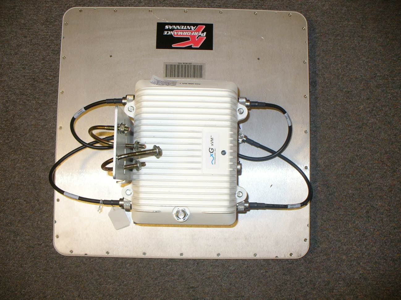
VEYCN3200R1
Sep 29, 2014Dual Band Routing Modem
Equipment Class
DTS - Digital Transmission System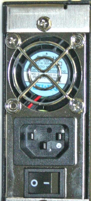
VEYXMAXBTS100
Dec 16, 2007xMax VOIP Base Transceiver Station
Equipment Class
DTS - Digital Transmission System