VEYXMAXBTS100xMax VOIP Base Transceiver Station
Vislink Technologies, Inc.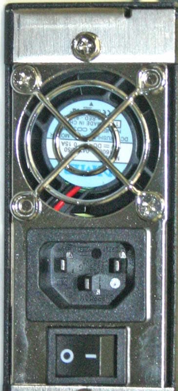
Click to zoom
Application Details
- Equipment Class
- DTS - Digital Transmission System
- Date of Grant
- Dec 16, 2007
- Application Purpose
- Original Equipment
- Date of Application
- Jul 16, 2007
- Equipment Note
- xMax VOIP Base Transceiver Station
- Frequency Range
- 902.00000000 - 928.00000000
- Company
- Vislink Technologies, Inc.
- Country
- United States
Documents & Files
Document Text
Text extracted from the exhibit documents filed with the FCC. Open a document above to read the original.
Users Manual
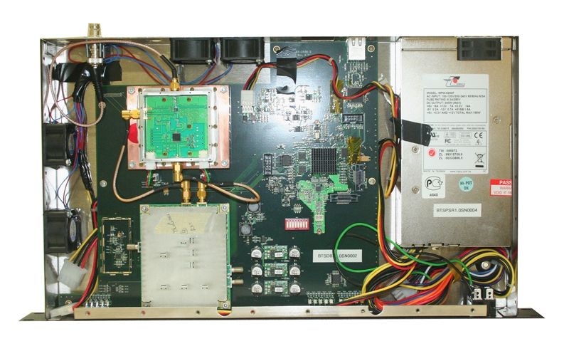
240 S Pineapple Ave, Ste 701, Sarasota, FL-34236 Tel: (941) 954-8701 Fax: (941) 954-8595 xMax VOIP BTS Operation Manual Version 1.2 Draft Copy 240 S Pineapple Ave, Ste 701, Sarasota, FL-34236 Tel: (941) 954-8701 Fax: (941) 954-8595 2 Table Of Contents • Introduction 2 • Physical Device 4 • AC Power Port 5 • Antenna Ports 6 • Ethernet Port 7 • Status Indicator 8 • Powering ON the xMax VOIP BTS 9 • Powering OFF the xMax VOIP BTS 9 • Technical Support 10 • Certification 10 • Warranty Information 10 240 S Pineapple Ave, Ste 701, Sarasota, FL-34236 Tel: (941) 954-8701 Fax: (941) 954-8595 3 Introduction: xMax Voice Over Internet Protocol (VOIP) Base Transceiver Station (BTS) is a transceiver device. The device operates in the unlicensed 900 MHz band under Part 15 of the FCC's rules. The bandwidth of the device is 26MHz (902-928MHz). The device is used for communicating with xMax Handsets operating in the unlicensed 900 MHz band under Part 15 of the FCC's rules. This device is a commercial unit and should be installed by licensed technician. This device is capable of transmitting/receiving voice and data services to and from xMax handsets. The xMax VOIP BTS is installed with all the necessary software to make wireless VOIP phone calls using xG proprietary physical layer technology. Notice: This device complies with Part 15 of the FCC Rules. Operation is subject to the following two conditions: (1) this device may not cause harmful interference, and (2) this device must accept any interference received, including interference that may cause undesired operation. Notice: Changes or modifications to this equipment not expressly approved by xG could void the user's authority to operate the equipment. 240 S Pineapple Ave, Ste 701, Sarasota, FL-34236 Tel: (941) 954-8701 Fax: (941) 954-8595 4 Physical Device: The xMax VOIP BTS is housed in a standard rackmount 1U chassis. The dimensions of the device are 19”*10.19”*1.75” Pictures of this device are shown below: Figure 1: xMax VOIP BTS Front/Side View Figure 2: xMax VOIP BTS Rear View 240 S Pineapple Ave, Ste 701, Sarasota, FL-34236 Tel: (941) 954-8701 Fax: (941) 954-8595 5 AC Power Port: AC Power: The device operates of 110V/220VAC; 50/60Hz and single-phase AC power line. The device is connected to the AC power line5 using a standard 3-prong power connector. This is shown in the following pictures: Figure 3: Power Connector and Rear Toggle Switch The Toggle switch on the rear end (near the power connector) is the main switch. This switch is used to turn ON and turn OFF the device. The device has a second Toggle switch installed at the front of the device. This is shown in the following picture: Figure 4: BTS Front View with Front Toggle Switch In a typical rack mount installation, access to the rear side is sometimes difficult. So the Toggle switch in the front is used to turn the device ON and OFF. To turn ON the device, both the rear and front switch has to be in the ON position (This is labeled ‘1’ on the switch). The device is turned OFF when either of the switches is flipped to OFF position (labeled as’0’ on the switch). 240 S Pineapple Ave, Ste 701, Sarasota, FL-34236 Tel: (941) 954-8701 Fax: (941) 954-8595 6 Antenna Ports: The device has 4 antenna ports. Only one port has the Chassis Mount BNC connector installed. The remaining three ports are open and no connector is installed on these slots. These open slots are used for future expansion of the device. A picture of the antenna port is shown below: Figure 5: Antenna Ports The impedance of the chassis mount BNC female connector is 50 Ohms. For proper operation of this device, this connector is connected to a 50 ohms coaxial cable with BNC male connector. Any 50 ohms coaxial cable with female BNC connector on one end and antenna on the other end can be used. However, the recommended coaxial cable is LMR- 900. The recommended antenna for this unit is 902-928MHz omni-directional antenna with either gain ranging from unity to 6dBi. Before turning ON the device, please connect the antenna using the recommended coaxial cable to the chassis mount BNC connector installed on the rear of the unit. The cable and antenna acts like a load to the xMax VOIP BTS. Never turn the unit ON without installing the cable and antenna. 240 S Pineapple Ave, Ste 701, Sarasota, FL-34236 Tel: (941) 954-8701 Fax: (941) 954-8595 7 Ethernet Port: A 10/100Mbps RJ-45 Ethernet connector is installed on the rear of the device as shown in the picture below: Figure 6: Ethernet Port The Ethernet Port is used to connect the Base Station to the SIP server. Connect the SIP server to the Base station before powering ON the xMax VOIP BTS. 240 S Pineapple Ave, Ste 701, Sarasota, FL-34236 Tel: (941) 954-8701 Fax: (941) 954-8595 8 Status Indicator: There are five LEDs installed on the front Panel. These LEDs are bicolor and will turn Green or Red depending on the status of the xMax VOIP BTS. A picture of these LEDs is shown below: Figure 7: Status Indicator LEDs Description of these LEDs is as follows: LED1: BTS ON/OFF LED2: Ethernet TX LED3: Ethernet RX LED4: TX Error LED5: RX Error 240 S Pineapple Ave, Ste 701, Sarasota, FL-34236 Tel: (941) 954-8701 Fax: (941) 954-8595 9 Powering ON the xMax VOIP BTS: Follow the following steps to turn on the device: 1- Toggle the front and rear switch in the OFF position. 2- Connect the power chord to the AC (110V main line) 3- Connect the coaxial cable and antenna to the Antenna port. 4- Connect the Ethernet cable to the Ethernet Port. 5- Flip the rear power switch in the ON position. 6- Flip the front power switch in the ON position. At this time, you will hear fans running inside the device and you will notice the left most LED turn green. The device is powered ON. Powering OFF the xMax VOIP BTS: Follow the following steps to turn OFF the device: 1- Flip the front toggle switch in the OFF position. The fans inside the unit will stop and the Green LED (the left most LED in the Status Indicator) will be …
Text truncated - open the document above for the full version.
Test Report
FAU EMI R&D LAB 2129.01 EMI Research and Development Laboratory Department of Electrical Engineering Florida Atlantic University 3998 FAU Blvd, Suite 310 Boca Raton, Florida 33431 (561) 361-4390 Technical Report No. 07-062 “EMI Evaluation of the XG Technology, XG-VOIP-BTS to FCC Part 15, Class A Conducted and Radiated Emission Requirements.” Performed: 29 May 2007 Customer: XG Technology, Inc. 7771 W. Oakland Park Blvd. #231 Sunrise, FL 33351 Company Official responsible for product(s) tested: _______________________________ Nadeem Khan, Engineer (954) 572-0395 ext. 3327 Test Performed and Reported By: _______________________________ Thierry Jean-Charles, BSEE FAU EMI R&D Laboratory Approved by: ________________________________ Vichate Ungvichian, Ph.D., P.E. Director, FAU EMI R&D Laboratory Technical Report No. 07-062 Page 1 of 25 Technical Report No. 07-062 Page 2 of 25 1. INTRODUCTION The XG Technology, Inc. XG-VOIP-BTS is a base station for transmission and reception of voice over IP, using an XG proprietary modulation scheme within the ISM band of 902 to 928 MHz. The unit, with maximum operating clock frequency of 210 MHz, was evaluated for compliance to the FCC CFR-47, Part 15, Class A requirements. The device was evaluated for both transmitting mode and receiving mode. The results apply only to the specific items of equipment, configurations and procedures supplied to the Florida Atlantic University EMI R&D Laboratory as reported in this document. 2. OBJECTIVE This evaluation was performed to verify conformance of the XG Technology, XG-VOIP-BTS module to the U.S. Federal Communications Commission (FCC), Code of Federal Regulations (CFR), Title 47 - Telecommunication, FCC Part 15 Subpart B- Unintentional Radiators, Sections 15.107(b) and 15.109 (b), FCC Class A conducted and radiated emission requirements, and Subpart C- Intentional Radiators, Section 15.247, Operation within the bands 902-928 MHz. 3. CONCLUSION The XG Technology, XG-VOIP-BTS unit met the FCC, Part 15 Subpart B, Class A conducted and radiated emission requirements, as well as the requirements for Section 15.247, operation within the band of 902-928 MHz, as described in the following pages. Technical Report No. 07-062 Page 3 of 25 4. TEST PROCEDURES AND RESULTS 4.1 TEST PROCEDURES The measurement techniques identified in the measurement procedure of ANSI C63.4-2003 "American National Standard of Measurement of Radio-Noise Emissions from Low-Voltage Electrical and Electronic Equipment in the Range of 9 kHz to 40 GHz" were followed as close as practical during this evaluation. Complete details and specific procedures used are discussed in the respective test result sections. 4.2 CONDUCTED EMISSIONS TEST RESULTS 4.2.1 CONDUCTED POWERLINE EMISSIONS The XG Technology, XG-VOIP-BTS unit was evaluated for conducted emission requirements for both transmitting and receiving modes of operation. The module, powered by an internal switching power supply, was assessed with an antenna set on top of a metal sheet. The data was transmitted and received correctly as confirmed by the XG Technology Engineer. Photographs 1 and 2 show the setup used during the evaluations. The system was installed in the FAU EMI Research facilities conducted emissions shielded enclosure, on a wooden test table 80 centimeters above the ground plane floor and 40 centimeters from the rear wall. The device was then plugged into a Line Impedance Stabilization Network (LISN) EMCO Model No.3825/2R Serial No. 1095. Conducted power line emissions were measured on both the phase and neutral lines with reference to earth ground, over the specified 150 kHz to 30 MHz range on a Hewlett Packard HP 8566B Spectrum Analyzer operated in the peak detection mode, in conjunction with HP 85685A Preselector, with a bandwidth of 9 kHz obtained through the HP 85650A Quasi Peak Adapter. Figures 1 and 2 show the conducted emissions on both the phase and neutral lines measured in the receiver peak detection mode. EUT Photographs 1 & 2: Conducted Emission Setup Technical Report No. 07-062 Page 4 of 25 4.2.2 RECEIVING MODE Figure 1 presents the results for the system evaluated in the receiving mode. Figure 1: Phase and Neutral Conducted Emissions Technical Report No. 07-062 Page 5 of 25 4.2.3 TRANSMITTING MODE Figure 2 presents the results for the unit evaluated in the transmitting mode. The unit was set to transmit voice packets of 30 ms duration using an XG proprietary modulation scheme within the ISM band of 902 to 928 MHz. Figure 2: Phase and Neutral Conducted Emissions Technical Report No. 07-062 Page 6 of 25 Technical Report No. 07-062 Page 7 of 25 From the above figures, the emissions that exceeded or were within 5 dB of the limit are reported in Table 1. Since the peak emissions are more than 5 dB below the average limit, there are no values to report on Table 1. Line Tested Frequency (kHz) Peak Value (dBμV) QP Value (dBμV) Average Value (dBμV) Avg. Limit (dBμV) Margin to Avg. Limit (dB)* Phase Neutral Phase Neutral Phase Neutral Phase Neutral Phase Neutral Table 1: Conducted Emission Peak Measurement *Margin to Avg. Limit (dB) = Avg. Limit (dBμV) – the measured value (either Peak, Quasi-Peak or Average Value) in dBμV It can be seen that on both the phase and neutral lines, the emissions did not exceed the limits. Hence, the system is in compliance. Technical Report No. 07-062 Page 8 of 25 4.3 RADIATED EMISSIONS TEST RESULTS 4.3.1 UNINTENTIONAL RADIATED EMISSIONS The XG Technology, XG-VOIP-BTS unit was set up on a wooden table 80 centimeters above the ground plane turntable of the Semi-Anechoic test site, as shown in Photographs 3 & 4. An antenna, set on a metal sheet (ground plane), was connected to the antenna jack of EUT. The XG-VOIP-BTS unit was connected to 110V/ 60 Hz power outlet located at the center of the turntable. The unit was evaluated for both transmitting and receiving mode. An EMCO, Model 3104, S/N 299988A, the Broadband Biconical antenna was installed on an E…
Text truncated - open the document above for the full version.
Test Report
FAU EMI R&D LAB 2129.01 EMI Research and Development Laboratory Department of Electrical Engineering Florida Atlantic University 3998 FAU Blvd, Suite 310 Boca Raton, Florida 33431 (561) 361-4390 Technical Report No. 07-112 EMI Evaluation of the XG Technology, XG-VOIP-BTS to FCC Part 15, Class A Conducted and Radiated Emission Requirements, and Section 15.247, “Operation within the band of 902 – 928 MHz.” Performed: 11 October 2007 Customer: XG Technology, Inc. 7771 W. Oakland Park Blvd. #231 Sunrise, FL 33351 Company Official responsible for product(s) tested: _______________________________ Nadeem Khan, Engineer (954) 572-0395 ext. 3327 Test Performed and Reported By: _______________________________ Thierry Jean-Charles, BSEE FAU EMI R&D Laboratory Approved by: ________________________________ Vichate Ungvichian, Ph.D., P.E. Director, FAU EMI R&D Laboratory Technical Report No. 07-112 Page 1 of 29 Technical Report No. 07-112 Page 2 of 29 1. INTRODUCTION This document reports the FCC compliance results for the XG Technology, Inc.’s XG-VOIP-BTS, with updated software revision FVXGBTS101107-A. The unit is a base station for transmission and reception of voice over IP. The device transmits at a fixed frequency (914.3 MHz) within the ISM band of 902 to 928 MHz using an XG proprietary modulation scheme. The unit, with maximum operating clock frequency of 210 MHz, was evaluated for compliance to the FCC CFR-47, Part 15, Class A requirements as well as Section 15.247. The device was evaluated for both transmitting mode and receiving mode. The results apply only to the specific items of equipment, configurations and procedures supplied to the Florida Atlantic University EMI R&D Laboratory as reported in this document. 2. OBJECTIVE This evaluation was performed to verify conformance of the XG Technology, XG-VOIP-BTS module to the U.S. Federal Communications Commission (FCC), Code of Federal Regulations (CFR), Title 47 - Telecommunication, FCC Part 15 Subpart B- Unintentional Radiators, Sections 15.107(b) and 15.109 (b), FCC Class A conducted and radiated emission requirements, and Subpart C- Intentional Radiators, Section 15.247, “Operation within the bands 902-928 MHz”. 3. CONCLUSION The XG Technology, XG-VOIP-BTS unit met the FCC, Part 15 Subpart B, Class A conducted and radiated emission requirements, as well as the requirements for Section 15.247, operation within the band of 902-928 MHz, as described in the following pages. Technical Report No. 07-112 Page 3 of 29 4. TEST PROCEDURES AND RESULTS 4.1 TEST PROCEDURES The measurement techniques identified in the measurement procedure of ANSI C63.4-2003 "American National Standard of Measurement of Radio-Noise Emissions from Low-Voltage Electrical and Electronic Equipment in the Range of 9 kHz to 40 GHz" were followed as close as practical during this evaluation. Complete details and specific procedures used are discussed in the respective test result sections. 4.2 CONDUCTED EMISSIONS TEST RESULTS 4.2.1 CONDUCTED POWERLINE EMISSIONS The XG Technology, XG-VOIP-BTS unit was evaluated for conducted emission requirements for both transmitting and receiving modes of operation. The module, powered by an internal switching power supply, was assessed with an antenna attached on a thin metal-sheet counterpoise and was placed set on top of the wooden test table. The data was transmitted and received correctly as confirmed by the XG Technology Engineer. Photographs 1 and 2 show the setup used during the evaluations. The system was installed in the FAU EMI Research facilities conducted emissions shielded enclosure, on a wooden test table 80 centimeters above the ground plane floor and 40 centimeters from the rear wall. The device was then plugged into a Line Impedance Stabilization Network (LISN) EMCO Model No.3825/2R Serial No. 1095. Conducted power line emissions were measured on both the phase and neutral lines with reference to earth ground, over the specified 150 kHz to 30 MHz range on a Hewlett Packard HP 8566B Spectrum Analyzer operated in the peak detection mode, in conjunction with HP 85685A Preselector, with a bandwidth of 9 kHz obtained through the HP 85650A Quasi Peak Adapter. Figures 1 and 2 show the conducted emissions on both the phase and neutral lines measured in the receiver peak detection mode. EUT Photographs 1 & 2: Conducted Emission Setup Technical Report No. 07-112 Page 4 of 29 4.2.2 RECEIVING MODE Figure 1 presents the results for the system evaluated in the receiving mode. Figure 1: Phase and Neutral Conducted Emissions Technical Report No. 07-112 Page 5 of 29 4.2.3 TRANSMITTING MODE Figure 2 presents the results for the unit evaluated in the transmitting mode. The unit was set to transmit voice packets of 30 ms duration using an XG proprietary modulation scheme within the ISM band of 902 to 928 MHz. Figure 2: Phase and Neutral Conducted Emissions Technical Report No. 07-112 Page 6 of 29 Technical Report No. 07-112 Page 7 of 29 From the above figures, the emissions that exceeded or were within 5 dB of the limit are reported in Table 1. Since the peak emissions are more than 5 dB below the average limit, there are no values to report on Table 1. Line Tested Frequency (kHz) Peak Value (dBμV) QP Value (dBμV) Average Value (dBμV) Avg. Limit (dBμV) Margin to Avg. Limit (dB)* Phase Neutral Table 1: Conducted Emission Peak Measurement *Margin to Avg. Limit (dB) = Avg. Limit (dBμV) – the measured value (either Peak, Quasi-Peak or Average Value) in dBμV It can be seen that on both the phase and neutral lines, the emissions did not exceed the limits. Hence, the system is in compliance. Technical Report No. 07-112 Page 8 of 29 4.3 RADIATED EMISSIONS TEST RESULTS 4.3.1 UNINTENTIONAL RADIATED EMISSIONS The XG Technology, XG-VOIP-BTS unit was setup on a wooden table 80 centimeters above the ground plane turntable of the Semi-Anechoic test site, as shown in Photographs 3 & 4. An antenna, set on a metal sheet (ground plane), was connected to the ant…
Text truncated - open the document above for the full version.
Test Report
FAU EMI R&D LAB 2129.01 EMI Research and Development Laboratory Department of Electrical Engineering Florida Atlantic University 3998 FAU Blvd, Suite 310 Boca Raton, Florida 33431 (561) 361-4390 Technical Report No. 07-112-x Addendum to the Technical Report No. 07-112, EMI Evaluation of the XG Technology, XG-VOIP-BTS to FCC Part 15, Class A Conducted and Radiated Emission Requirements, and Section 15.247, “Operation within the band of 902 – 928 MHz.” Performed: 04 December 2007 Customer: XG Technology, Inc. 7771 W. Oakland Park Blvd. #231 Sunrise, FL 33351 Company Official responsible for product(s) tested: _______________________________ Nadeem Khan, Engineer (954) 572-0395 ext. 3327 Test Performed and Reported By: _______________________________ Thierry Jean-Charles, BSEE FAU EMI R&D Laboratory Approved by: ________________________________ Vichate Ungvichian, Ph.D., P.E. Director, FAU EMI R&D Laboratory Technical Report No. 07-112-x Page 1 of 9 Technical Report No. 07-112-x Page 2 of 9 1. INTRODUCTION This document is an addendum to Technical Report No. 07-112 which documents the FCC compliance results for the XG Technology, Inc.’s XG-VOIP-BTS with software revision FVXGBTS101107-A. The unit was evaluated for compliance to the FCC CFR-47, Part 15, Class A requirements as well as Section 15.247. This document reports the results for the calculated peak power and the power spectral density (PSD) as required per FCC CFR-47, Part 15, Section 15.247 following the measurement procedures described in the FCC document “Measurement of Digital Transmission Systems Operating under Section 15.247, March 2005,” and Agilent Technologies “Application Note 150-2.” The results apply only to the specific items of equipment, configurations and procedures supplied to the Florida Atlantic University EMI R&D Laboratory as reported in this document. 2. OBJECTIVE This evaluation was performed to verify conformance of the XG Technology, XG-VOIP-BTS module to the U.S. Federal Communications Commission (FCC), Code of Federal Regulations (CFR), Title 47 - Telecommunication, FCC Part 15 Subpart C- Intentional Radiators, Section 15.247, “Operation within the bands 902-928 MHz” for conducted peak power and PSD measurements. 3. CONCLUSION The XG Technology, XG-VOIP-BTS unit met the FCC, Part 15 Subpart C- Intentional Radiators, Section 15.247, “Operation within the band of 902-928 MHz”, as described in the Technical Report No. 07-112 and this addendum. Technical Report No. 07-112-x Page 3 of 9 4. TEST PROCEDURES AND RESULTS 4.1 TEST PROCEDURES The measurement techniques identified in the measurement procedure of ANSI C63.4-2003 "American National Standard of Measurement of Radio-Noise Emissions from Low-Voltage Electrical and Electronic Equipment in the Range of 9 kHz to 40 GHz", as well as the FCC document “Measurement of Digital Transmission Systems Operating under Section 15.247 (March 2005),” were followed as close as practical during this evaluation. Note also that measurement methods defined by Agilent Technologies “Application Note 150-2” were also observed. Complete details and specific procedures used are discussed in the respective test result sections. 4.2 PULSE WIDTH AND REPETION FREQUENCY From Figure 1 provided by XG Technology, Inc., the pulse characteristics of the XG-VOIP-BTS are determined as follows: • Pulse width τ eff = 100 ns • Pulse repetition frequency, PRF = 1.66 MHz. The pulse desensitization factor α L can be computed as per Agilent Technologies “Application Note 150-2”, (page 8): () PRF effL ×=τα 10 log20 (1) () 69 10 1066.110100log20×××= − () 166.0log20 10 = dBdB6.15598.15−≈−= Figure 1: XG-VOIP-BTS pulse repetition frequency Note that the measurement data shown in Figure 16 of Technical Report 07-112, Section 4.3.2.2 (page 24) refers to the packet transmission rate. Technical Report No. 07-112-x Page 4 of 9 4.3 MAXIMUM OUTPUT POWER This section describes a corrective measurement data to Section 4.3.2.2 (page 24) of technical report 07-112. The maximum output power of the XG Technology XG-VOIP-BTS unit was measured using the HP 8566B spectrum analyzer (SA) on the peak detector mode, while the “bypass” instrument function of the HP 85650A Quasi-Peak Adapter was activated. The coaxial output port for the XG-VOIP-BTS antenna was connected to SA in series with a HP 8495B variable attenuator set to 40 dB. Since the 11 MHz 6-dB bandwidth of the signal exceeds SA IF bandwidth limit, the peak power was determined using the pulse desensitization technique defined in the Agilent Technologies “Application Note 150-2”. The spectrum analyzer was centered to the peak of the fundamental frequency (916.02 MHz). Figure 2 presents the measurement data with resolution bandwidth (B) and the frequency span set to 100 kHz and 40 MHz, respectively. In Figure 3, the frequency span was reduced to 0 Hz and the video trigger of SA was activated. Note that for both measurements, the resolution bandwidth met the Agilent Technologies “Application Note 150-2” (Equation 3) requirements for pulse desensitization using line spectra measurements: B = 100 kHz < 0.1 PRF. Figure 2: XG-VOIP-BTS SA Display for Peak Power Measurement Technical Report No. 07-112-x Page 5 of 9 Figure 3: Peak Power Measurement with 0 Hz Span (Packet Transmission Rate of 30.35 ms) SA Reading (dBm) External Attenuation (dB) Cable Loss (dB) α L (dB) Corrected Power (dBm)* Corrected Power (mW) -33.95 40 0.61 -15.60 22.26 168.10 Table 1: Peak Power Measurement where the corrected power is given by the relation: * Corrected Power (dBm) = SA Reading (dBm) + External Attenuation (dB) + Cable Loss (dB) - α L (dB) Note that the value from Figure 3 was used for the computation. It can be seen from the data above that the calculated maximum peak output power is 22.26 dBm, corresponding to 168.1 milliwatts, which is lower than the 1 watt limit. Hence, the device meets the maximum output power requirements as per Section 15.247. Technical Report No. 07-112-x Page …
Text truncated - open the document above for the full version.
Contact Information
Applicant
Michael C Bond(CFO)
Technical Contact
xG Technology, Inc.Joseph Bobier
[email protected]954-572-0395
7771 West Oakland Park Boulevard · Sunrise, Florida · United States
Non-Technical Contact
Blooston, Mordkofsky, Dickens, Duffy & PrendergastHarold Mordkofsky
[email protected]202-828-5520
Test Firm
ADVANCED COMPLIANCE SOLUTIONS, INC.Vichate Ungvichian
Technical Specifications
| # | Rule Parts | Frequency Range | Power Output |
|---|---|---|---|
| 1 | 15C | 902 MHz - 928 MHz | 168.00 mW |
Other Applications from Vislink Technologies, Inc.
VEYCN3200R1
Sep 29, 2014Dual Band Routing Modem
Equipment Class
DTS - Digital Transmission System
VEYXMODR2
Sep 03, 2013xMod
Equipment Class
DTS - Digital Transmission System