VG8XM059KYYGEMicrowave Oven
Guangdong Midea Kitchen Appliances Manufacturing Co.,Ltd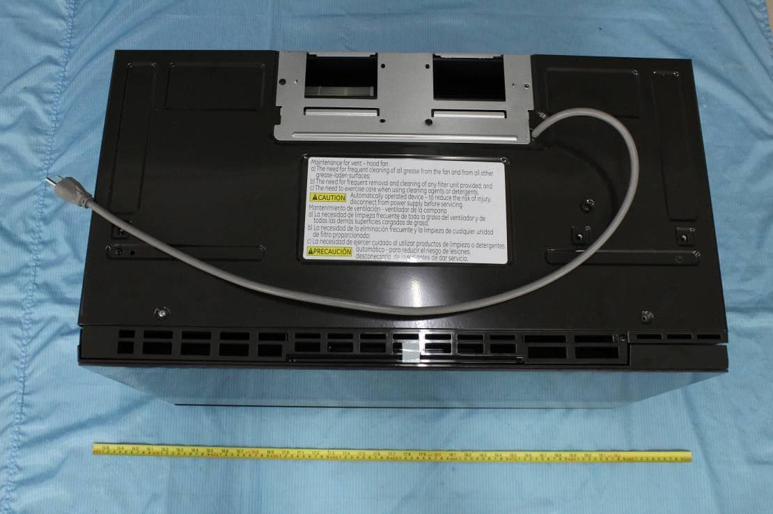
Click to zoom
Application Details
- Equipment Class
- 8CC - Part 18 Consumer Device
- Date of Grant
- May 26, 2020
- Application Purpose
- Original Equipment
- Date of Application
- May 26, 2020
- Equipment Note
- Microwave Oven
- Frequency Range
- 2450.00000000 - 2450.00000000
- Country
- China
Documents & Files
Document Text
Text extracted from the exhibit documents filed with the FCC. Open a document above to read the original.
Users Manual
MICROWAVE OVEN HOODS IMPORTANT SAFETY NOTICE THIS INFORMATION IS INTENDED FOR USE BY INDIVIDUALS POSSESSING ADEQUATE BACKGROUNDS IN ELECTRICAL, ELECTRONIC AND MECHANICAL EXPERIENCE. ANY ATTEMPT TO REPAIR A MAJOR APPLIANCE MAY RESULT IN PERSONAL INJURY AND PROPERTY DAMAGE. THE MANUFACTURER OR SELLER CANNOT BE RESPONSIBLE FOR THE INTERPRETATION OF THIS INFORMATION, NOR CAN IT ASSUME ANY LIABILITY IN CONNECTION WITH ITS USE. DISCONNECT POWER BEFORE SERVICING. IMPORTANT-RECONNECT ALL GROUNDING DEVICES ALL PARTS OF THIS APPLIANCE CAPABLE OF CONDUCTING ELECTRICAL CURRENT ARE GROUNDED. IF GROUNDING WIRES, SCREWS, STRAPS, CLIPS, NUTS OR WASHERS USED TO COMPLETE A PATH TO GROUND ARE REMOVED FOR SERVICE, THEY MUST BE RETURNED TO THEIR ORIGINAL POSITION AND PROPERLY FASTENED. PRECAUTIONS TO BE OBSERVED BEFORE AND DURING SERVICING TO AVOID POSSIBLE EXPOSURE TO EXCESSIVE MICROWAVE ENERGY. OPERATED WITH THE DOOR OPEN. MAGNETRON. 1. INTERLOCK OPERATION 2. PROPER DOOR CLOSING 3. SEAL AND SEALING SURFACES (ARCING, WEAR AND OTHER DAMAGE) 4. DAMAGE TO OR LOOSENING OF HINGES AND LATCHES 5. EVIDENCE OF DROPPING OR ABUSE ANY SERVICE TEST OR INSPECTION WITHIN THE MICROWAVE GENERATING COMPARTMENTS, CHECK THE MAGNETRON, WAVE GUIDE AND CAVITY FOR PROPER ALIGNMENT, INTEGRITY AND CONNECTIONS. B. DO NOT OPERATE OR ALLOW THE OVEN TO BE C. IF THE OVEN OPERATES WITH THE DOOR OPEN: 1. INSTRUCT THE USER NOT TO OPERATE THE OVEN. 2. CONTACT THE MANUFACTURER AND THE CENTER MICROWAVE OVENS (MWOs) BEFORE ACTIVATING THE D. CHECK THE FOLLOWING SAFETY ITEMS ON ALL E. BEFORE TURNING ON MICROWAVE POWER FOR A. IF OVEN IS OPERABLE, PERFORM MICROWAVE EMISSION CHECK PRIOR TO EXAMINING THE UNIT. FOR DEVICES RADIOLOGICAL HEALTH IMMEDIATELY. IN THE INTERLOCK MONITOR, DOOR SEAL AND MICROWAVE GENERATION AND TRANSMISSION SYSTEMS SHALL BE REPAIRED, REPLACED OR ADJUSTED BY PROCEDURE DESCRIBED IN THIS MANUAL BEFORE THE OVEN IS RELEASED TO THE OWNER. F. ANY DEFECTIVE OR MISADJUSTED COMPONENTS G. A MICROWAVE LEAKAGE CHECK TO VERIFY COMPLIANCE WITH THE FEDERAL PERFORMANCE STANDARD SHOULD BE PERFORMED ON EACH OVEN PRIOR TO RELEASE TO THE OWNER. GROUNDING SPECIFICATIONS Leakage Current 0.5 mA. (Max.) Ground Path Resistance 0.14 ohm (Max.) INSTALLATION REQUIREMENTS ELECTRICAL MWO Power Power Source Line Current Over Current Protection * Requires 120 volt, 20 Amp. parallel, grounded separate circuit. Working Voltage 1050 Watts 14.8 Amps. (150 Watts) 120 VAC, 60 Hz. 20 Amps* 108-132 VAC MICROWAVE LEAKAGE TEST 1. Place 275 ml. water in 1000 ml. beaker (WB64x73). 2. Place beaker in center of oven glass. 3. Set meter to 2450 MHz scale. 4. Turn “on” for 5 minute test. 5. Hold probe perpendicular to surface being tested and scan surfaces at rate of one inch/sec. 6. Maximum leakage 4 mW/cm Test the following areas: • Entire perimeter of door and control panel • Viewing surface of door window • Exhaust vents NOTE: Maximum allowable leakage is 4 mW/cmis used to allow for measurement and meter accuracy. Inform the manufacturer of any oven found to have emission in excess of 5 mW/cm. 2 Make repairs to bring the unit into compliance at no cost to owner and try to determine cause. Instruct owner not to use oven until it has been brought into compliance. 2 2 5 mW/cm 2 WARNING TO PREVENT ELECTRICAL SHOCK, USE EXTREME CAUTION WHEN DIAGNOSING OVEN WITH OUTER CASE REMOVE D AND POWER "ON". THE HIGH VOLTAGE SECTION OF THE POWER SUPPLY, INCLUDING FILAMENT LEADS, HAVE THE POTENTIAL WITH RESPECT TO GROUND TO REACH 4000 VOLTS! HIGH VOLTAGE CAPACITOR The high voltage capacitor has an internal shunt resistor to automatically discharge the capacitor when the oven turns “off”. Under normal operation the capacitor should fully discharge within 30 seconds. WARNING ALWAYS BE CERTAIN THE CAPACITOR IS DISCHARGED BEFORE SERVICING. DISCHARGE BY PLACING AN INSULATED HANDLE SCREW DRIVER BETWEEN THE DIODE CONNECTION AND OVEN CHASSIS GROUND. PERFORMANCE TEST 1. Measure line voltage( loaded). This test is based on normal voltage variations of 108V to 132V. Low voltage will cause low output power and temperature rise. 2. Place WB64X73 beaker containing one liter of water (1000ml, 55°F~75°F) on turntable and record the starting water tempture with an accurate thermometer. (DO NOT USE ANY OTHER LOAD OR DISH AS RESULT WILL VARY FROM STANDARD !) 3. Set at HIGH power for 2 minutes, and 3 sec. 4. Turn on the oven. 5. Record end water temperature. The minimum difference between the initial and ending temperature should be: 30°F @ 120 V. HOW TO TEST INTERLOCKS 1. Disconnect power, open control panel, and discharge capacitor. 2. Check Continuity of Com and N.O.: • Door Closed - 0 Ω • Door Open - ∞ Ω • TECHNICAL DATA SHEET • INTERLOCKS (DOOR Latch Switches) Interlocks are designed as follows: Primary - Top switch operated by top latch pawl connected to line (L) leg. B C A Primary Switch Secondary Switch Monitor Switch MONITOR SWITCH The monitor switch B is located between the top and bottom interlocks. The monitor switch is operated indirectly by the bottom latch pawl. HOW TO TEST MONITOR 1. Disconnect power, open control panel, and discharge capacitor. 2. Disconnect monitor switch leads, and test at terminals: • Door Closed - ∞ Ω • Door Open - 0 Ω 3. Reconnect switch wiring. 4. Test Circuit Operation: A) Connect temporary jumper across relay contacts and primary switch to simulate shorted switch contacts. Locate convenient connections in circuit to be certain COM and N.O. terminals are used. B) Connect Ohm meter (low scale) across the two line terminals of appliance power cord. Continuity must show: • Door Closed - Some Ω • Door Open - 0 Ω C) Remove 20 Amp. Fuse - Circuit must open ( ∞ Ohms). If not, check wiring of monitor and interlock circuits. D) WARNING After test remove temporary jumper leads! from interlocks and relay. Reconnect monitor switch leads, replace fuse. E) Replacement of any parts in monitor circuit requires repeating this entire test procedure. IMPORTANT: Check for microwave leaka…
Text truncated - open the document above for the full version.
Cover Letter(s)
Guangdong Midea Kitchen Appliances Manufacturing Co.,Ltd No.6, Yong An Road, Beijiao, Shunde, Foshan,Guangdong,China TEL:+86-0757-23606480 Em ail: [email protected] . Version 1.1( 2016-04-27) Page 1 of 1 QB-SA-041 Declar ation of Difference To Whom It May Concern, We, Guangdong Midea Kitchen Appliances Manufacturing Co.,Ltd , hereby declar e that there are some differences between our Multiple Models and test products. Details as below: Products tested Name Microwave Oven Model TM059K6CA-P(GE) (FCC ID: VG8XM059KYYGE) Project No. RSZ200121552-EM Multiple Models XM059KYY-P(GE), XM059KYYY-P(GE), CVM721M2NCS5 □No Difference√Differences as the below Testing Products Multiple Mo dels Details M059K6CA-P(GE) XM059KYY-P(GE), XM059KYYY-P(GE) CVM721M2NCS5 X indicate Controller Tpe,X=E or T. Y Y or YYY indicate different appearance,Y=0~9 or A~Z. Notes: Products teste d -the products tested by BACL Multiple Model- have the same or similar appearance, structure, PCB, Material and function to the testing products. Besides the differences in the table above, we declare the products are identical We guarantee all the information provided above is true, and notice that we’ll bear all the consequences caused by any false information or concealing Best Regards, Signature: Print Name: Xue Wenfei Title: Engineer
Cover Letter(s)
Guangd ong Midea Kitchen Appliances Manufacturing Co.,Ltd No.6 , Yong An Road, Beijiao, Shunde, Foshan,Guangdong,China TEL:+86-0757-23606480 Email: [email protected] FCC Authorization 2/24/2020 FEDERAL COM MUNICATIONS COMMISSIONS Authorization and Evaluation Division 7435 Oakland Mills Road Columbia, MD 21046 Subject: Agent Authorization To whom it may concern: We, Gu angdong Midea Kitchen Appliances Manufacturing Co.,Ltd, the undersigned, hereby authorize Bay Area Compliance Laboratories Corporation to act on its behalf in all matters relating to application for Equipment authorization, including the signing of all documents relating to these matters. All acts carried out by Bay Area Compliance Laboratory Corporation on our behalf shall have the same effect as our own action. We, the undersigned, hereby certify that we are not subject to a denial of federal benefits, that includes FCC benefits, pursuant to Section 5301 of the Anti-Drug Abuse Act of 1988, 21 U.S.C. 862. This authorization is valid until further written notice from the applicant. Sincerely Yours, Signature: Print Name: Xue Wenfei Titel: Engineer QA- FR-170-B
Cover Letter(s)
Guangd ong Midea Kitchen Appliances Manufacturing Co.,Ltd No.6 , Yong An Road, Beijiao, Shunde, Foshan,Guangdong,China TEL:+86-0757-23606480 Email: [email protected] FCC Confid ential Authorization 2 /24/2020 FEDERAL COMMUNICATIONS COMMISSIONS Authorization and Evaluation Division 7435 Oakland Mills Road Columbia, MD 21046 Subject:Co nfidentiality Request regarding application for certification of FCC ID:VG8XM059KYYGE In accordance with Sections 0.457 and 0.459 of the Commission’s Rules, (Guangdong Midea Kitchen Appliances Manufacturing Co.,Ltd) hereby requests long-term confidential treatment of information accompanying this application as outlined below: Bl oc k Dia g ram Op eration Descrip tion Schematics The above materials contain proprietary and confidential information not customarily released to the public. The public disclosure of these materials provides unjustified benefits to its competitors in the market. Sincerely Yours, Signature: Print Name: Xue Wenfei Title: Engineer We declare that Schematics is not confidential.
External Photos
EXHIBIT B - EUT EXTERNAL PHOTOGRAPHS
ID Label/Location Info
EXHIBIT A - FCC ID LABEL AND LOCATION FCC ID Label FCC ID Label Location Information Specifications: Text is Black or white in color and is left justified. Labels are printed in indelible ink on permanent adhesive backing or silk-screened onto the EUT or shall be affixed at a conspicuous location on the EUT. Label here
Internal Photos
EXHIBIT C - EUT INTERNAL PHOTOGRAPHS WIfi Module BT Module
Test Report
Note: This report must not be used by the customer to claim product certification, approval, or endorsement by A2LA* or any agency of the Federal Government. This report may contain data that are not covered by the A2LA accreditation and are marked with an asterisk “★”. BACL is not responsible for the authenticity of any test data provided by the applicant. Data included from the applicant that may affect test results are marked with an asterisk ’*’. Customer model name, addresses, names, trademarks etc. are not considered data. This report cannot be reproduced except in full, without prior written approval of the Company. Unless otherwise stated the results shown in this test report refer only to the sample(s) tested. This report is valid only with a valid digital signature. The digital signature may be available only under the Adobe software above version 7.0. FCC PART 18 TEST REPORT For Guangdong Midea Kitchen Appliances Manufacturing Co., Ltd No.6, Yong An Road, Beijiao, Shunde, Foshan, Guangdong, China R e p o r t T y p e : O r i gi n a l R e p o r t P r o d u c t T y p e: M i c r o w a ve O ve n Report Number: RSZ200121552-00 Report Date: 2020-02-16 Reviewed By: Alvin Huang Lab Manager Prepared By: Bay Area Compliance Laboratories Corp. (Shenzhen) 6/F., West Wing, Third Phase of Wanli Industrial Building, Shihua Road, Futian Free Trade Zone, Shenzhen, Guangdong, China Tel: +86-755-33320018 Fax: +86-755-33320008 www.baclcorp.com.cn FCC ID: VG8XM059KYYGE Bay Area Compliance Laboratories Corp. (Shenzhen) Report No.: RSZ200121552-00 FCC Part 18 Page 2 of 23 TABLE OF CONTENTS GENERAL INFORMATION ....................................................................................................................................... 3 PRODUCT DESCRIPTION FOR EQUIPMENT UNDER TEST (EUT) ..................................................................................... 3 OBJECTIVE ................................................................................................................................................................... 3 RELATED SUBMITTAL(S)/GRANT(S) ............................................................................................................................. 3 TEST METHODOLOGY .................................................................................................................................................. 3 MEASUREMENT UNCERTAINTY .................................................................................................................................... 4 TEST FACILITY ............................................................................................................................................................. 4 OPERATING CONDITION/TEST CONFIGURATION .......................................................................................... 5 JUSTIFICATION ............................................................................................................................................................. 5 EUT EXERCISE SOFTWARE .......................................................................................................................................... 5 SPECIAL ACCESSORIES ................................................................................................................................................. 5 EQUIPMENT MODIFICATIONS ....................................................................................................................................... 5 SUPPORT EQUIPMENT LIST AND DETAILS .................................................................................................................... 5 EXTERNAL CABLE LIST AND DETAILS ......................................................................................................................... 5 CONFIGURATION OF TEST SETUP ................................................................................................................................. 5 BLOCK DIAGRAM OF TEST SETUP ................................................................................................................................ 6 SUMMARY OF TEST RESULT ................................................................................................................................. 7 TEST EQUIPMENT LIST ........................................................................................................................................... 8 CONDUCTED EMISSIONS ........................................................................................................................................ 9 APPLICABLE STANDARD .............................................................................................................................................. 9 EUT SETUP .................................................................................................................................................................. 9 EMI TEST RECEIVER SETUP ......................................................................................................................................... 9 TEST PROCEDURE ...................................................................................................................................................... 10 TEST RESULTS SUMMARY .......................................................................................................................................... 10 TEST DATA ................................................................................................................................................................ 10 RADIATION HAZARD MEASUREMENT ............................................................................................................. 13 APPLICABLE STANDARD ............................................................................................................................................ 13 ENVIRONMENTAL CONDITIONS .....................…
Text truncated - open the document above for the full version.
Test Setup Photos
EXHIBIT D - TEST SETUP PHOTOGRAPHS Conducted Emissions - Front View Conducted Emissions - Side View Radiated Emissions - Front View (30 MHz – 1 GHz) Radiated Emissions - Rear View (30 MHz – 1 GHz) Radiated Emissions - Front View (Above 1 GHz) Radiated Emissions - Rear View (Above 1 GHz)
Contact Information
Applicant
Jilin Ye(Engineer)
Test Firm
Bay Area Compliance Laboratories Corp. (Shenzhen)Well Wang
[email protected]+86 (0) 755 33320018
Technical Specifications
| # | Rule Parts | Frequency Range | Power Output |
|---|---|---|---|
| 1 | 18 | 2.45 GHz - 2.45 GHz | - |
Other Applications from Guangdong Midea Kitchen Appliances Manufacturing Co.,Ltd

VG8TJ018GXX
Dec 18, 2025Microwave Oven
Equipment Class
8CC - Part 18 Consumer Device
VG8TC934DYYM
Dec 15, 2025Microwave Oven
Equipment Class
8CC - Part 18 Consumer Device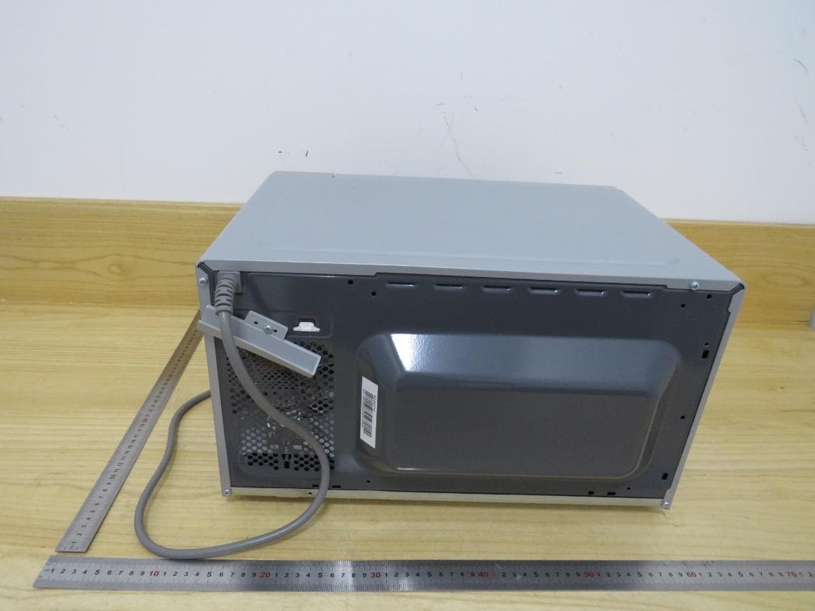
VG8AM0P02YY
Sep 22, 2024Microwave Oven
Equipment Class
8CC - Part 18 Consumer Device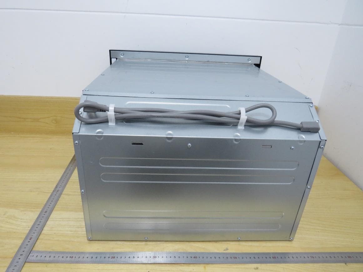
VG8TC934DYY
Sep 22, 2024Microwave Oven
Equipment Class
8CC - Part 18 Consumer Device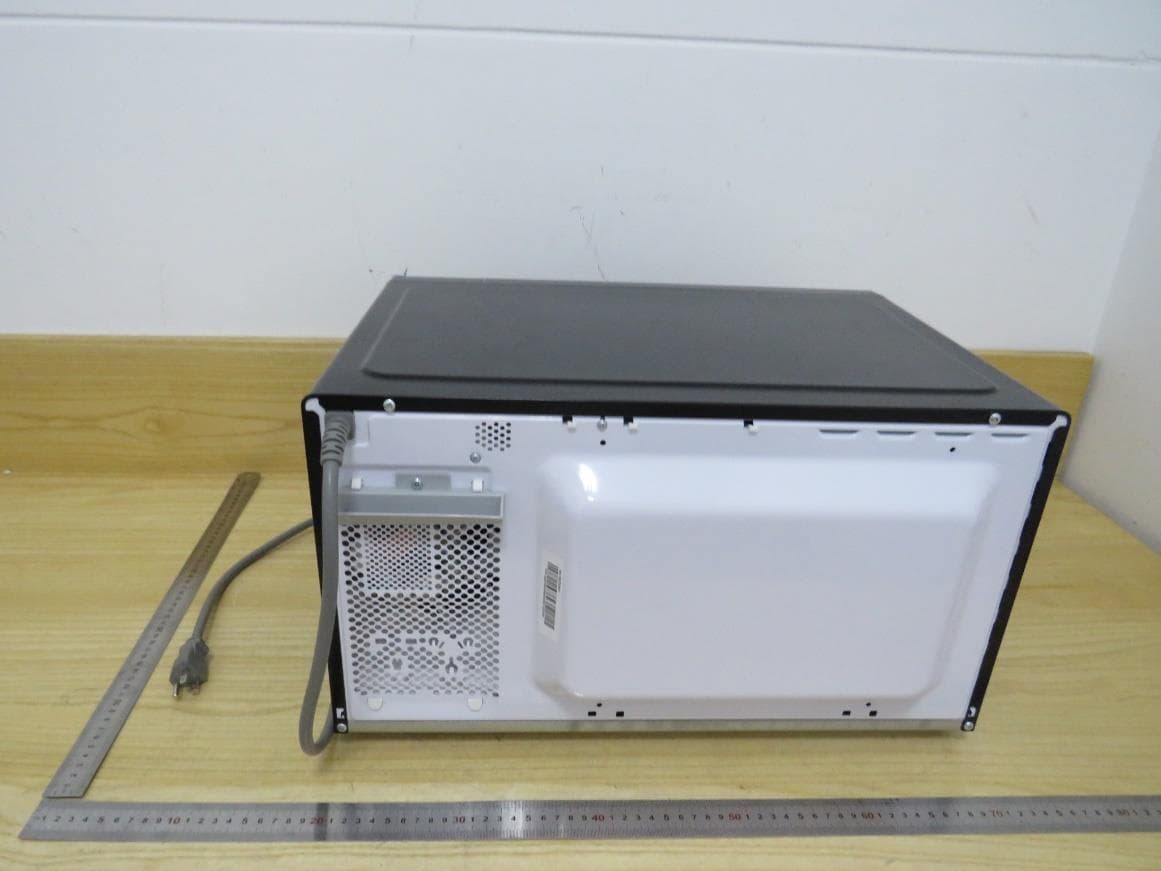
VG8EM9P04YY
Aug 27, 2024Microwave Oven
Equipment Class
8CC - Part 18 Consumer Device