VGA4422Transmitter(remote control)
BIG KING HORN SPEAKER ENT. CO., LTD.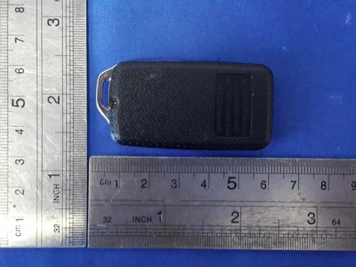
Click to zoom
Application Details
- Equipment Class
- DSC - Part 15 Security/Remote Control Transmitter
- Date of Grant
- Oct 21, 2015
- Application Purpose
- Original Equipment
- Date of Application
- Oct 21, 2015
- Equipment Note
- Transmitter(remote control)
- Frequency Range
- 433.92000000 - 433.92000000
- Country
- Taiwan
Documents & Files
Document Text
Text extracted from the exhibit documents filed with the FCC. Open a document above to read the original.
Users Manual
Arming: Press & Release the “Lock” button Silent Arming: Press & Release the “3rd” button Twice in 3 sec. Disarming: Press & Release the “Unlock” button Silent Disarming: Press & Release the “3rd” button Twice in 3 sec Page 1 Remote Control Quick Reference Guide THE SIREN WILL CHIRP ONCE THE PARKING LIGHTS WILL FLASH ONCE THE DOORS WILL LOCK (IF CONNECTED) THE PARKING LIGHTS WILL FLASH ONCE THE DOORS WILL LOCK (IF CONNECTED) THE SIREN WILL CHIRP TWICE THE PARKING LIGHTS WILL FLASH TWICE THE DOORS WILL UNLOCK (IF CONNECTED) THE PARKING LIGHTS WILL FLASH TWICE THE DOORS WILL UNLOCK (IF CONNECTED) Table Of Contents Owner’s Guide Arming the System ....................... 3 Disarming the System ................. 4 Emergency Override .................... 4 System Armed & Activated ........... 5 Panic ............................................ 5 Sensor By-Pass ............................ 5 Auxiliary Channel ......................... 6 3rd Channel .................................. 6 Remote Controlled Anti-Carjack ... 6 Anti-Carjacking ............................. 7 Valet Mode ................................... 8 LED Status Indicator .................... 8 Auxiliary Sensor & Prewarn .......... 9 Installation Instructions How To Program Remote Control ............. 9 How To Program Features ...................... 10 Programmable Features .................. 10 - 12 Wiring Diagram ....................................... 13 Door Lock/Unlocking Systems ................ 14 This device complies with part 15 of the FCC Rules. Operation is subject to the following two conditions, (1) This device may not cause harmful interference and, (2) This device must accept any interference received, including interference that may cause undesired operation. The manufacturer is not responsible for any radio or TV interference caused by unauthorized modifications to this equipment. Such modifications could void the user's authority to operate the equipment. Any Changes or modifications not expressly approved by the party responsible for compliance could void the user's authority to operate the equipment. 2 X 2 X Emergency Override: Panic:Press & Hold the “Lock” Button for 3 Sec’s, with the ignition “Off” Shock Sensor & Prewarn Bypass: 1) Arm the alarm by, Pressing & Releasing the “Lock” button 2) Within 2 seconds Press & Release the “3rd” button. To Activate the Auxiliary Channel: Press & Hold The “3rd” Button for 3 Seconds To Activate the 3rd Channel: Press & Hold The “4th” Button for 3 Seconds To Activate Remote Anti-Carjack: Press & Hold the “4th” button, for 3 Secs, withthe ignition “On” (programmable feature # 10) Page 2 Then 1. 2. Operate Remote Start Unit Operate Window Roll-Up Unit Open Electric Trunk Operate Window Roll-Up Unit Operate Remote Start Unit THEN WITHIN 10 SECONDS PRESS & RELEASE VALET BUTTON THE SIREN WILL SOUND THE PARKING LIGHTS WILL FLASH Hold 3 seconds Hold 3 seconds Hold 3 seconds Hold 3 seconds The system may be "Armed" by any of 3 methods: 1) Remote Control Arming: Press & Release the “Lock” button Page 3 Arming the Alarm Upon Arming:• The siren will chirp one time. (3 times if there is open zone) • The parking lights will flash once. • The doors will lock. (If an optional interface is connected) • The starter interrupt will engage. • The LED Status Indicator will begin to flash slowly. - If a zone is open, (for example a car door), when arming, the alarm will still arm, but will bypass the open zone until the zone is secured (siren will chirp 3 times). 3) To Passively Arm: Turn Ignition “Off”, Then Close all Doors. Automatic “Last Door Arming” is a programmable feature which allows the alarm to arm itself and, if desired, lock the doors upon arming. If on, anytime the ignition is turned off, and then a door is opened and closed: • The Siren will chirp once to confirm arming countdown has begun. • The LED Status Indicator will begin to flash rapidly. Thirty seconds later: • The siren will chirp & the lights will flash once. • The LED Status Indicator will begin to flash slowly. • The starter interrupt will engage. - The alarm is now fully armed. The doors will lock at this time, if programmed to do so, and if the vehicle is equipped. - The system can not Last Door Arm if a protected zone is open. Should a ve- hicle door be opened during the arming countdown, the countdown will stop and start over again when the door is closed. AUTO REARM (programmable) allows the Alarm to Rearm itself, if it is Disarmed. 2) SILENT Remote Control Arming: Press & Release the “3rd” button Twice within 3 seconds THE SIREN WILL CHIRP ONCE THE PARKING LIGHTS WILL FLASH ONCE THE DOORS WILL LOCK (IF CONNECTED) THE PARKING LIGHTS WILL FLASH ONCE THE DOORS WILL LOCK (IF CONNECTED) 2 X The system may be "Disarmed" by any of 3 methods: 1) Remote Control Disarming: Press & Release the “Unlock” button 2) SILENT Remote Control Disarming: Press & Release the “3rd” button Twice within 3 sec Upon Disarm:• The siren will chirp twice. (4 chirps if alarm has activated & reset) • The parking lights will flash twice. (4 times if alarm has activated) • The doors will unlock. (If an optional interface is connected) • The starter interrupt will disengage. • The LED Status Indicator begins flashing rapidly for Automatic Rearming, until alarm Rearms or a vehicle door is opened. 2-STAGE DISARM: If Disarming the alarm while it is triggered (siren sounding), the first press of any remote control button will only silence the siren/horn. A second press of the “Unlock” button will Disarm the alarm. IMMOBILIZER MODE: If this mode is programmed “On”, the starter interrupt will remain engaged after the alarm is Disarmed, until the ignition is turned “On” and you Press & Release the Valet button. (Refer to programmable feature # 5) To Start Vehicle: . 1. Disarm the alarm, then Turn “On” the vehicle’s ignition 2. Press & Release the Valet Button. Step 1:With the system in the armed condition, enter the vehicle via the driver's door (be aw…
Text truncated - open the document above for the full version.
Cover Letter(s)
BIG KING HORN SPEAKER ENT. CO., LTD. Confidentiality Letter To: Federal Communications Commission Authorization and Evaluation Division 7435 Oakland Mills Road Columbia, MD Subject: Permanent Confidentiality Request for FCC ID: VGA4422 Product: Transmitter(remote control) Model: A30 We hereby request confidential treatment of information accompanying this application as outlined below: Block Diagram Schematics Operational Description The above materials contain trade secrets and proprietary information not customarily released to the public. The public disclosure of these materials may be harmful to the applicant and provide unjustified benefits to its competitors. The applicant understands that pursuant to Section 0.457 & 0.459 of the Rules, disclosure of this application and all accompanying documentation will not be made before the date of the Grant for this application. Sincerely, signature : name / title: C.W. Yiu / PRESIDENT address: NO.5,LANE 39, AN-LO ROAD, CHUNG-HO CITY, TAIPEI HSIEN 235 Taiwan
External Photos
.
ID Label/Location Info
20.02mm 12.08mm
Internal Photos
Antenna location
Test Report
FCC ID: VGA4422 Keyway Testing Technology Co., Ltd. Report No. 15KWE105142F Page 1 of 20 FCC TEST REPORT for BIG KING HORN SPEAKER ENT. CO., LTD. Transmitter (remote control) Model Number:A30 FCC ID: VGA4422 Prepared for : BIG KING HORN SPEAKER ENT. CO., LTD. Address : NO.5,LANE 39, AN-LO ROAD, CHUNG-HO CITY, TAIPEI HSIEN 235 TAIWAN Prepared by : Keyway Testing Technology Co., Ltd. Address : Baishun Industrial Zone, Zhangmutou Town, Dongguan, Guangdong, China Tel: 86-769-8718 2258 Fax: 86-769-8718 1058 Report No. : 15KWE105142F Date of Test : Oct. 10~15, 2015 Date of Report : Oct. 15, 2014 FCC ID: VGA4422 Keyway Testing Technology Co., Ltd. Report No. 15KWE105142F Page 2 of 20 TABLE OF CONTENTS Test Report Declaration Page 1. GENERAL PRODUCT INFORMATION ............................................................................ 4 1.1. Product Function .................................................................................................................... 4 1.2. Description of Device (EUT) .................................................................................................. 4 1.3. Independent Operation Modes .............................................................................................. 4 2. TEST SITES ..................................................................................................................... 5 2.1. Test Facilities ......................................................................................................................... 5 2.2. List of Test and Measurement Instruments ............................................................................ 6 3. TEST SET-UP AND OPERATION MODES ...................................................................... 7 3.1. Principle of Configuration Selection ....................................................................................... 7 3.2. Block Diagram of Test Set-up ................................................................................................ 7 3.3. Test Operation Mode and Test Software ............................................................................... 7 3.4. Special Accessories and Auxiliary Equipment ....................................................................... 7 3.5. Countermeasures to Achieve EMC Compliance .................................................................... 7 3.6. Test Environment: .................................................................................................................. 7 4. EMISSION TEST RESULTS ............................................................................................. 8 4.1. Radiated Emission Test ......................................................................................................... 8 5. CALCULATION OF AVERAGE FACTOR ....................................................................... 14 6. 20DB OCCUPY BANDWIDTH ........................................................................................ 17 6.1. Limits .................................................................................................................................... 17 7. DWELL TIME .................................................................................................................. 18 7.1. Limits .................................................................................................................................... 18 8. PHOTOGRAPHS OF TEST SET-UP .............................................................................. 19 9. PHOTOGRAPHS OF THE EUT ...................................................................................... 20 FCC ID: VGA4422 Keyway Testing Technology Co., Ltd. Report No. 15KWE105142F Page 3 of 20 Keyway Testing Technology Co., Ltd. Applicant: Address: BIG KING HORN SPEAKER ENT. CO., LTD. NO.5,LANE 39, AN-LO ROAD, CHUNG-HO CITY, TAIPEI HSIEN 235 TAIWAN Manufacturer: Address: BIG KING HORN ELECTRONIC (SHANGHAI) CO.,LTD NO.3689, BEI QING ROAD, SONG SHAN VILLAGE,HUA XIN TOWN, QING PU , SHANG HAI, CHINA E.U.T: Transmitter(remote control) Model Number: A30 Trade Name: VGA4422 Serial No.: ------ Date of Receipt: Oct. 10, 2015 Date of Test: Oct. 10~15, 2015 Test Specification: FCC Part 15, Subpart C: Oct. 1, 2014 ANSI C63.10:2013 Test Result: The equipment under test was found to be compliance with the requirements of the standards applied. Issue Date: Oct. 15, 2015 Tested by: Reviewed by: Approved by: Jack Bu / Engineer Andy Gao / Supervisor Jade Yang/ Supervisor Other Aspects: None. Abbreviations: OK/P=passed fail/F=failed n.a/N=not applicable E.U.T=equipment under tested This test report is based on a single evaluation of one sample of above mentioned products. It is not permitted to be duplicated in extracts without written approval of Keyway Testing Technology Co., Ltd. FCC ID: VGA4422 Keyway Testing Technology Co., Ltd. Report No. 15KWE105142F Page 4 of 20 1. GENERAL PRODUCT INFORMATION 1.1. Product Function Refer to Technical Construction Form and User Manual. 1.2. Description of Device (EUT) Description : Transmitter(remote control) M/N : A30 Power Supply : DC 6V Operation Frequency : 433.92MHz Modulation Technology : ASK Antenna Type : Integral Antenna Gain : 2dBi HW version : H01 SW version : V01 1.3. Independent Operation Modes The basic operation modes are: 1.3.1. Transmitting mode(TX Mode) Note: There four button and 15 programmable features, we pretest all mode, only the up button(Arming) and first programming features was worst, all data was in this mode. 1.3.2. Normal mode. 1.3.3. Transmitting mode(Low voltage Mode) Remark: For all test, used new battery. FCC ID: VGA4422 Keyway Testing Technology Co., Ltd. Report No. 15KWE105142F Page 5 of 20 2. TEST SITES 2.1. Test Facilities Lab Qualifications : 944 Shielded Room built by ETS-Lindgren, USA Date of completion: March 28, 2011 966 Chamber built by ETS-Lindgren, USA Date of completion: March 28, 2011 Certificated by TUV Rheinland, Germany.…
Text truncated - open the document above for the full version.
Test Setup Photos
Radiated Emission
Contact Information
Applicant
C.W. Yiu(PRESIDENT)
Test Firm
Keyway Testing Technology Co., Ltd.Jade Yang
Technical Specifications
| # | Rule Parts | Frequency Range | Power Output |
|---|---|---|---|
| 1 | 15.231 | 433.92 MHz - 433.92 MHz | - |
Other Applications from BIG KING HORN SPEAKER ENT. CO., LTD.
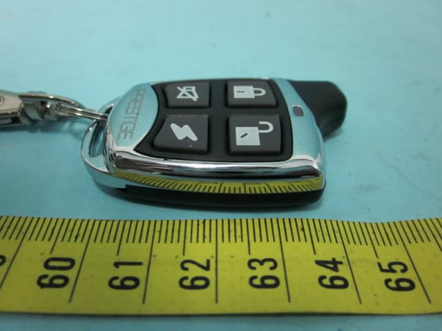
VGA114BP
Aug 01, 2012TRANSMITTER
Equipment Class
DSC - Part 15 Security/Remote Control Transmitter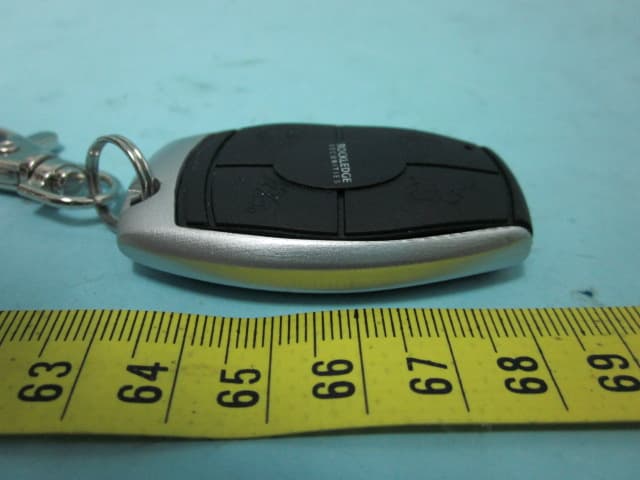
VGAROC4TX
Aug 01, 2012TRANSMITTER
Equipment Class
DSC - Part 15 Security/Remote Control Transmitter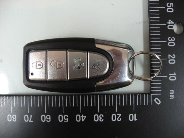
VGAPROPL4TX
May 23, 2012TRANSMITTER
Equipment Class
DSC - Part 15 Security/Remote Control Transmitter
VGA4421
Jul 27, 2011TRANSMITTER
Equipment Class
DSC - Part 15 Security/Remote Control Transmitter
VGA4412
Jul 27, 2011TRANSMITTER
Equipment Class
DSC - Part 15 Security/Remote Control Transmitter