VGAPROPL4TXTRANSMITTER
BIG KING HORN SPEAKER ENT. CO., LTD.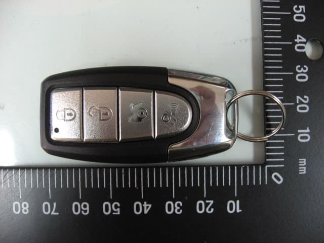
Click to zoom
Application Details
- Equipment Class
- DSC - Part 15 Security/Remote Control Transmitter
- Date of Grant
- May 23, 2012
- Application Purpose
- Original Equipment
- Date of Application
- May 23, 2012
- Equipment Note
- TRANSMITTER
- Frequency Range
- 433.92000000 - 433.92000000
- Country
- Taiwan
Documents & Files
Document Text
Text extracted from the exhibit documents filed with the FCC. Open a document above to read the original.
Users Manual
Arming: Press & Release the “Lock” button Silent Arming: Press & Release the “3rd” button Twice in 3 sec. Disarming: Press & Release the “Unlock” button Silent Disarming: Press & Release the “3rd” button Twice in 3 sec Page 1 Remote Control Quick Reference Guide 2 X 2 X THE SIREN WILL CHIRP ONCE THE PARKING LIGHTS WILL FLASH ONCE THE DOORS WILL LOCK (IF CONNECTED) THE PARKING LIGHTS WILL FLASH ONCE THE DOORS WILL LOCK (IF CONNECTED) THE SIREN WILL CHIRP TWICE THE PARKING LIGHTS WILL FLASH TWICE THE DOORS WILL UNLOCK (IF CONNECTED) THE PARKING LIGHTS WILL FLASH TWICE THE DOORS WILL UNLOCK (IF CONNECTED) Table Of Contents Owner’s Guide Arming the System ....................... 3 Disarming the System ................. 4 Emergency Override .................... 4 System Armed & Activated ........... 5 Panic ............................................ 5 Sensor By-Pass ............................ 5 Auxiliary Channel ......................... 6 3rd Channel .................................. 6 Remote Controlled Anti-Carjack ... 6 Anti-Carjacking ............................. 7 Valet Mode ................................... 8 LED Status Indicator .................... 8 Auxiliary Sensor & Prewarn .......... 9 Installation Instructions How To Program Remote Control ............. 9 How To Program Features ...................... 10 Programmable Features .................. 10 - 12 Wiring Diagram ....................................... 13 Door Lock/Unlocking Systems ................ 14 IMPORTANT NOTE: To comply with the FCC RF exposure compliance requirements, no change to the antenna or the device is permitted. Any change to the antenna or the device could result in the device exceeding the RF exposure requirements and void user’s authority to operate the device. To Activate the Auxiliary Channel: Press & Hold The “3rd” Button for 3 Seconds To Activate the 3rd Channel: Press & Hold The “4th” Button for 3 Seconds To Activate Remote Anti-Carjack: (programmable feature # 10) Press & Hold the “4th” button, for 3 Secs, with the ignition “On” Emergency Override: Panic:Press & Hold the “Lock” Button for 3 Sec’s, with the ignition “Off” Shock Sensor & Prewarn Bypass: 1) Arm the alarm by, Pressing & Releasing the “Lock” button 2) Within 2 seconds Press & Release the “3rd” button. Page 2 Then 1. 2. Operate Remote Start Unit Operate Window Roll-Up Unit Hold 3 seconds Open Electric Trunk Operate Window Roll-Up Unit Operate Remote Start Unit THEN WITHIN 10 SECONDS PRESS & RELEASE VALET BUTTON Hold 3 seconds THE SIREN WILL SOUND THE PARKING LIGHTS WILL FLASH Hold 3 seconds Hold 3 seconds The system may be "Armed" by any of 3 methods: 1) Remote Control Arming: Press & Release the “Lock” button Page 3 Arming the Alarm Upon Arming:• The siren will chirp one time. (3 times if there is open zone) • The parking lights will flash once. • The doors will lock. (If an optional interface is connected) • The starter interrupt will engage. • The LED Status Indicator will begin to flash slowly. - If a zone is open, (for example a car door), when arming, the alarm will still arm, but will bypass the open zone until the zone is secured (siren will chirp 3 times). 3) To Passively Arm: Turn Ignition “Off”, Then Close all Doors. Automatic “Last Door Arming” is a programmable feature which allows the alarm to arm itself and, if desired, lock the doors upon arming. If on, anytime the ignition is turned off, and then a door is opened and closed: • The Siren will chirp once to confirm arming countdown has begun. • The LED Status Indicator will begin to flash rapidly. Thirty seconds later: • The siren will chirp & the lights will flash once. • The LED Status Indicator will begin to flash slowly. • The starter interrupt will engage. - The alarm is now fully armed. The doors will lock at this time, if programmed to do so, and if the vehicle is equipped. - The system can not Last Door Arm if a protected zone is open. Should a ve- hicle door be opened during the arming countdown, the countdown will stop and start over again when the door is closed. AUTO REARM (programmable) allows the Alarm to Rearm itself, if it is Disarmed. 2) SILENT Remote Control Arming: Press & Release the “3rd” button Twice within 3 seconds THE SIREN WILL CHIRP ONCE THE PARKING LIGHTS WILL FLASH ONCE THE DOORS WILL LOCK (IF CONNECTED) THE PARKING LIGHTS WILL FLASH ONCE THE DOORS WILL LOCK (IF CONNECTED) 2 X
Users Manual
The system may be "Disarmed" by any of 3 methods: 1) Remote Control Disarming: Press & Release the “Unlock” button 2) SILENT Remote Control Disarming: Press & Release the “3rd” button Twice within 3 sec Upon Disarm:• The siren will chirp twice. (4 chirps if alarm has activated & reset) • The parking lights will flash twice. (4 times if alarm has activated) • The doors will unlock. (If an optional interface is connected) • The starter interrupt will disengage. • The LED Status Indicator begins flashing rapidly for Automatic Rearming, until alarm Rearms or a vehicle door is opened. 2-STAGE DISARM: If Disarming the alarm while it is triggered (siren sounding), the first press of any remote control button will only silence the siren/horn. A second press of the “Unlock” button will Disarm the alarm. IMMOBILIZER MODE: If this mode is programmed “On”, the starter interrupt will remain engaged after the alarm is Disarmed, until the ignition is turned “On” and you Press & Release the Valet button. (Refer to programmable feature # 5) To Start Vehicle: . 1. Disarm the alarm, then Turn “On” the vehicle’s ignition 2. Press & Release the Valet Button. Step 1:With the system in the armed condition, enter the vehicle via the driver's door (be aware that the alarm will trigger when the door is opened). Step 2:Using your key, turn the vehicle’s ignition to the "On" position. Step 3: Within 10 seconds, Press & Release the Valet/ Override Switch. Page 4 Disarming the Alarm Emergency Override THEN WITHIN 10 SECONDS THE PARKING LIGHTS WILL FLASH TWICE THE DOORS WILL UNLOCK (IF CONNECTED) THE SIREN WILL CHIRP TWICE THE PARKING LIGHTS WILL FLASH TWICE THE DOORS WILL UNLOCK (IF CONNECTED) 2 X Regardless of method used to Arm the alarm, once Armed, the alarm will monitor all protected zones, and if an intrusion attempt is detected it will activate, or “trigger”. A trigger consists of the following: • The electronic siren, or optionally the vehicle’s horn, will start sounding. • The exterior parking lights will flash on and off repeatedly. An activation has a 30 second duration unless the system is disarmed using the remote control or the Valet /Override switch. If all protected zones are secure at the end of the trigger, the system will stop and rearm itself to detect further entry attempts. If a protected zone is still open at the end of the trigger cycle, the alarm will continue to re-trigger itself for up to six activated cycles before it resets itself and ignores the violated zone. Should it be needed in a threatening situation, or you feel the need to attract attention, the alarm can be triggered using the remote control. Your alarm fea- tures “Panic Mode”, which allows you to activate “Panic” from the “Arm/Lock” button. To Activate Remote Panic:Press & Hold the “Arm/Lock” Button, for 3 seconds, with the ignition “Off”. The shock sensor & Prewarn zone can be by-passed using the remote control. This may be useful in stormy weather. 1) Arm the alarm by, Pressing & Releasing the “Lock” button. 2) Within 2 seconds, Press & Release the “3rd” button. - The siren will chirp once to confirm sensor has been by-passed. - Upon Disarming the alarm, the sensor zone will reset. Sensor By-pass System Armed & Activated Remote Panic Operation Page 5 Then 2. THE SIREN WILL SOUND THE PARKING LIGHTS WILL FLASH Hold 3 seconds 1. The Auxiliary Channel may be used to operate an optional function. Possibili- ties include remote trunk release, remote car starting, or an on-demand re- mote window roll-up interface. Please see your Omega dealer for details on available options. To Activate the Auxiliary Channel: Press & Hold the “3rd” Button for 3 Seconds. - The alarm will Disarm upon activating the Auxiliary channel. - The Auxiliary Channel cannot be activated if the vehicle's ignition is "On". The programmable 3rd Channel may be used to operate an optional function, such as a remote start unit or an on-demand remote window roll-up interface. Please see your Omega dealer for details on available options. To Activate the 3rd Channel: Press & Hold the “4th” button for 3 Seconds. - The 3rd Channel can be programmed to Supply a (-) output when the alarm is Armed to operate a Window Roll-Up module (Programmable feature # 12). The Anti-Carjacking mode can be activated using the remote control. - Refer to next page for sequence details. (programmable feature # 10) To Activate Remote Anti-Carjack: Press & Hold The “4th” Button, For 3 Seconds, With The Ignition “On”. Page 6 The Auxiliary Channel Remote Anti-Carjack The 3rd Channel Auxiliary Output Hold 3 seconds Hold 3 seconds Opperate Remote Start Unit Opperate Window Roll- Up Unit Hold 3 seconds Open Electric Trunk Opperate Window Roll- Up Unit Opperate Remote Start Unit
Users Manual
Page 7 The Anti-Carjacking sequence may be activated by any of 3 methods: 1) Using the remote control, by holding down the Small “4th” Button for 3 seconds while the ignition is “On”. (programmable feature # 10) 2) When a door is Opened while the ignition is “On” (programmable feature # 10) 3) Every time the ignition is turned “On”. (Programmable feature # 9) 1) Anti-Carjacking activated using the transmitter: (programmable feature # 10) The Anti Car-Jacking operation may be activated by pressing and holding the remote control’s Small “4th” button for 3 seconds while the ignition is “On”. 2) Anti-Carjacking activated by an Open door: (programmable feature # 10) If programmable feature # 10 is “On”, the system will initiate the Anti-Carjacking sequence every time a vehicle door is opened while the ignition is “On”. 3) Anti-Carjacking activated by the ignition: (programmable feature # 9) If programmable feature # 9 is “On”, the system will initiate the Anti-Carjacking sequence every time the vehicle’s ignition is turned “On”. IMMOBILIZER MODE: If the “Immobilizer mode” is programmed “On”, the ignition activated anti-carjacking sequence will be cancelled and the “Immobilizer mode” disarmed by: first turning “On” the vehicle’s ignition, then Pressing & Releasing the valet button. (Refer to programmable feature # 5) Once the Anti-Carjacking sequence has begun, the user has 59 seconds to press the Valet/Override Switch in order to cancel the sequence. ORDER OF ANTI-CARJACKING SEQUENCE: - For first 20 seconds after the sequence has begun there are no signs. - From 21-30 seconds, the LED will blink slowly. - From 31-45 seconds, the LED will blink fast and the siren/horn will chirp once every 2 seconds. - From 46-60 seconds, the LED will blink fast and the siren/horn will chirp once per second. - If not cancelled yet, at 61 seconds the alarm will trigger. In the triggered condition: - The siren/horn will sound & The parking lights will flash. - The starter interrupt will engage. NOTE: Once the Anti-Carjack mode is triggered, the remote control will NOT stop the operation, nor will the system reset automatically. Once it is trig- gered, the Anti-Carjacking operation can only be deactivated by: 1) Turning the vehicle’s ignition “Off”. 2) Turning the vehicle’s ignition back “On”. 3) Within 10 seconds, Press & Release the Valet button. Programmable Anti-Carjacking Protection Page 8 Valet Mode Valet Mode can only be entered into while the alarm is Disarmed. Valet Mode turns off all of the alarm’s security features, (including Anti-Carjack). Valet Mode is designed for situations in which it is not convenient for the security portion of the alarm to be operational; for example during extended stopovers for vehicle servicing, loaning others your vehicle, maintenance, valet parking, washing, etc. The convenience features such as keyless entry will still operate. To Enter Valet Mode (Alarm MUST be Disarmed): Press & Hold the Valet Switch for 3 Seconds. -The LED Status Indicator will light solid Blue & the siren will emit a long chirp to confirm entry into Valet Mode. Now the system cannot become Armed. - The vehicle's ignition may be "On" or "Off" when entering Valet Mode. - To remind you its in Valet Mode ,The siren will chirp every time the vehicle’s ignition is turned “Off” To Exit Valet Mode:Simply Press & Release the Valet Switch. -The LED will turn off and the siren will emit a long chirp to confirm that the system has exited Valet Mode. Normal arming operations may be resumed. - The vehicle's ignition may be "On" or "Off" when exiting Valet Mode. The Blue LED Status Indicator visually shows the status of the alarm and also provides a high level of visual deterrence. The Blue LED Status Indicator Light is normally mounted where it can be seen by the driver, as well as from outside. Security System Status: The primary function of the Blue LED Status Indicator Light is to indicate the normal operating status of the security system: Off = The system is disarmed and not performing any automatic functions. On Constant = The system is in the Valet Mode. Flashing Slow = The system is fully Armed. Flashing Fast (while Disarmed) = Last Door Arming or Automatic Rearming. Zone Violation: Once alarm is Disarmed, LED will show which zone triggered alarm until the ignition is turned “On” (this clears unit’s memory). 2 flash & pause = Pin-Switch zone triggered alarm. 3 flash & pause = Door zone triggered alarm. 4 flash & pause = Sensor zone triggered alarm. Automatic Transmitter Verification: For the first 10 seconds after the vehicle’s ignition is turned "On", the LED Status Indicator will flash a number of times equal to the number of remote control transmitters which are programmed to operate the alarm. This indication can be from 1 Flash /pause up to 4 Flashes /pause, as the system can be operated by just one, or as many as 4 remote transmitters. The LED Status Indicator Page 9 Auxiliary Sensor: This security system is equipped with a plug-in port for an optional sensor to increase the effectiveness of the system. The comprehensive line of optional sensors offered is comprised of impact sensors, glass tampering sensors, and microwave/radar sensors which can detect motion inside and outside the vehicle. Prewarning Detection: This circuit requires connection to a dual zone sensor or detection device. When the sensor’s prewarn zone is triggered the siren will emit a series of chirps. To program remote controls to operate the alarm: Step 1:Turn "On" the vehicle's ignition. Step 2:Within 7 seconds press the Valet/Override Switch 5 times. The alarm will wolf the siren once to confirm entry into Remote Control Programming Mode. Step 3:Within 10 seconds, press any Button on each remote to be programmed. The siren will chirp to confirm each time a remote has been programed. If 10 seconds expire without any programming activity, or if the vehicle’s ignition is turned “Off”, the system will automatically exit Remote Contr…
Text truncated - open the document above for the full version.
Users Manual
Page 10 To access Features Programming Mode: Step 1:Turn the vehicle's ignition "On" then "Off". Step 2:Within 7 seconds of turning the ignition "Off", press the Valet Switch 5 times. The siren will wolf once confirming entry to Features Programming Mode. Step 3: Within 10 seconds of entering Features Programming Mode, press the Valet Switch the number of times equal to the number of the feature to be programmed. The siren will repeat the feature number with chirps to confirm. Step 4: After the system acknowledges the feature to be programmed: - press the “Lock” button on the remote to turn the feature “ON” (the siren will chirp once), or, - press the “Unlock” Button to turn feature “OFF” (siren will chirp twice). Note: Once the feature to be programed is selected, you can toggle the feature between its settings by pressing the “Lock” & “Unlock” buttons on the remote control. - To program more features, simply repeat Steps 3 and 4. - If 10 seconds expire without any programming activity, or if the vehicle’s igni- tion is turned “On”, the alarm will automatically exit Features Programming Mode. The siren will confirm exit. The alarm has 15 programmable features which allow it to be customized to suite many individual needs. The following pages provide a brief explanation for each feature, and notes its factory default setting. • = Default Factory Setting 1. Auto-Rearm: ( •On = 1 siren chirp / Off = 2 chirps) - Allows the Alarm to Rearm itself, if it is Disarmed. 2. Last Door Arming: (•On = 1 siren chirp / Off =2 chirps) - Configures the alarm to automatically arm itself 30 seconds after the last door is closed with the ignition “Off”. 3. Doors Lock w/ Last Door Arming: (•On = 1 siren chirp /Off = 2 chirps) - Adds the automatic locking of the vehicle's doors to the previous feature. How to Program Features Programmable Features Page 11 4. Double Pulse Unlock: ( 2 pulses = 1 siren chirp / • 1 pulse = 2 chirps) - Sets alarm to give 2 unlock pulses upon Disarm for cars that require it. 5. Immobilizer Mode: ( On = 1 siren chirp / •Off = 2 chirps) - If this mode is programmed “On”, the starter interrupt will remain engaged after the alarm is Disarmed, until the vehicle’s ignition is turned “On” and you Press & Release the Valet button. - Anti-Carjack: Upon disarming the “Immobilizer mode”, ignition activated anti- carjacking will be automatically cancelled, (if programmed “On”). - Remote Control Programming Mode: Immobilizer mode must be disarmed before entering remote control programming mode. 6. Siren & Horn or Horn: ( •Siren & Horn = 1 siren chirp / Horn = 2 chirps) - This feature configures the alarm’s Brown/White Horn-Honk output wire. This wire can be configured to honk the horn in addition to the Brown wire operating the siren, or take over all of the Siren’s functions SO THAT NO SIREN IS NECESSARY. - If Siren & Horn are selected: The horn will honk in addition to siren sounding only when the door, pin-switch, or ignition zones are violated. (The horn will not honk if alarm is triggered by the sensor zone, or during confirmation “chirps”) - If Only Horn is selected: The car horn will replace the siren and perform all of its functions. NOTE: Brown Siren wire will still be fully active & operational. 7. Shock Sensor False-Alarm Bypass: (On = 1 siren chirp / •Off = 2 chirps) - This feature will temporarily turn “Off” the shock sensor & pre-warn zone if: a. The pre-warn is triggered 10 times while the alarm is Armed. b. The instant trigger zone is triggered 5 times while the alarm is Armed. - The by-passed zones will be reinstated the next time the alarm is Armed. 8. Dome-Light Delay Bypass: (On = 1 siren chirp / •Off = 2 chirps) - This feature will turn “Off” the 3-chirp open zone warning when Arming the alarm with the remote control. This is for use in vehicles that keep the dome-light illuminated after the doors have been closed. 9. Ignition Activated Anti-Carjacking: (On = 1 siren chirp / •Off = 2 chirps) - This feature turns the alarm’s Ignition Anti-Carjacking feature “On” or “Off”. 10. Remote & Door Activated Anti-Carjacking: (On = 1 chirp / •Off = 2 chirps) - This feature turns both the alarm’s Remote Control and Open Door activated Anti-Carjacking features “On” or “Off”. Page 12 11. Dome-Light or Window Roll-Up: (•Dome-Light = 1 siren chirp / Window Roll-UP = 2 chirps) -Configures the alarm’s “Black/White” wire to operate the: a. Dome-Light: Supply a (-) output when the alarm is Disarmed to illuminate the vehicle’s Dome-Light for 30 seconds through the use of a relay, or b. Window Roll-Up or accessory: Supply a (-) output for 30 seconds when the alarm is Armed to operate a Window Roll-Up module or other accessory. 12. 3rd Channel Output: (•Momentary = 1 siren chirp / Window Roll-UP = 2 chirps) -Configures the alarm’s “Pink” wire to operate an: a. Accessory : Supply a (-) output as long as the small “4th” button on the remote control, is pressed & held while the vehicle’s ignition is “Off”, (max 30 seconds). b. Window Roll-Up or accessory: Supply a (-) output for 30 seconds when the alarm is Armed to operate a Window Roll-Up module or other accessory. 13. Ignition Door Lock/Unlock: (•On = 1 siren chirp / Off = 2 chirps) - Configures the alarm to Lock the vehicle's doors when the ignition is turned “On” and Unlock the vehicle’s doors when the ignition is turned “Off”. 14. “RFID” Add-On to Anti-Hijacking: (On = 1 siren chirp / •Off = 2 chirps) - Adds an “RFID” layer to both the Ignition & Open Door activated Anti-Hijacking features. (Note: Special RFID remote control required) JUMPER ON SIDE OF ALARM BRAIN: Lock Pulse Time: ( • .80 seconds = Jumper “In” / 4 seconds = Jumper “Out”) -Determines the length of the alarm’s door lock/unlock pulse output. 0.80 Sec 4.0 Sec -Press hold TX' button 5 seconds,LED will flash,TX'RFID is turned "On". -Press hold TX' button 5 seconds,LED will solid,TX'RFID is turned "Off".
Users Manual
Brown/White :This wire can be configured (Programmable feature # 6), to honk the horn in addition to the Brown wire operating the siren, or t ake over all of the Siren’ s functions SO THA T NO SIREN IS NECESSAR Y Café/con list a Blanca: Este cable se puede programar (función # 6), a sonar el claxon en conjunto al cable Café operar la Sirena, O T OMAR T ODAS LA FUNCIONES DE LA SIRENA P ARAQUE NO HAGA F AL TA INST ALAR SIRENA. Brown/White - Café/Blanco = (-Horn Output, Salida claxon -)Black/White - Negro/Blanco = (-Dome-Light , Salida luz de cabina-)Grey - Gris = (-Auxiliary output, Segundo canal auxiliar-)Pink - Rosado = (-3rd channel output, T ercer canal-) Orange - Naranja = (-S t arter Kill, Corte -) Blue - Azul = (-T rigger Input, Disp aro -) V iolet - V iolet a = (+Door Input, Puert a +) Green - V erde = (-Door Input, Puert a -) Y ellow - Amarillo = (+Accessory , Ignición +) Brown - Café = (+Siren/Horn, +Sirena/Claxon)Red - Rojo = (+12 V olt s, +12 V oltios) White - Blanco = (+Flashing Light s, +Luces) Black - Negro = (-Ground, -T ierra) Valet/Override Button 0.80 Sec 4.0 Sec Door Lock Pulse Time Jumper LED Status Indicator Optional Sensor K9 SS Green - V erde = (-Lock, -Cierre) Red - Rojo = (+12 V olt s) Blue - Azul = (- Unlock, - Apertura) Siren Pin-Switch (-) Pin-Switch (-) Battery Pin-Switch (+) 15 Amp + 12345 12345 12345 12345 12345 12345 12345 12345 12345 12345 12345 12345 Parking Lights / Luces 12345 12345 12345 12345 12345 12345 12345 12345 12345 12345 12345 Relay T runk Release Relay Relay Car Horn / Claxon Dome-Light (-) Auxiliary Output Page 13 Page 14 Negative Trigger System / Sistema Negativo: Doorlock Switch Ground Vehicle's Doorlock Relay Control Unit Lock Unlock Lock wire / Cable de cierre Unlock wire/ Cable de Apertura + Doorlock Actuators 5 Wire Reversal (Rest at ground): Cambio de Polaridad: Positive Trigger System / Sistema Positivo: Doorlock Switch (+) 12 Volts Vehicle's Doorlock Relay Control Unit Lock Unlock Lock wire / Cable de cierre Unlock wire/ Cable de Apertura + Doorlock Actuators (+)12 Volts Unlock Unlock Passenger Doorlock Switch Driver Doorlock Switch - Lock wire "Switch" side. -cable de Cierre, lado del switch -Lock wire "Motor" side. -cable de Cierre, lado Motor Cut both Lock and Unlock wires in car - Unlock wire "Switch" side. -cable de Apertura, lado del switch Lock Lock - Ground - Unlock wire "Motor" side. -cable de Apertura, lado Motor Green Blue Fuse 30 87 87a 30 87 87a Green Blue Lock Relay Unlock Relay Fuse 30 87 87a 30 87 87a Green Blue Lock Relay Unlock Relay (+)12 Volts Door Locking Systems / Sistemas De Cierre Notice : The changes or modifications not expressly approved by the party responsible for compliance could void the user’s authority to operate the equipment. IMPORTANT NOTE: To comply with the FCC RF exposure compliance requirements, no change to the antenna or the device is permitted. Any change to the antenna or the device could result in the device exceeding the RF exposure requirements and void user’s authority to operate the device. This device complies with Part 15 of the FCC Rules. Operation is subject to the following two conditions: (1) this device may not cause harmful interference, and (2) this device must accept any interference received, including interference that may cause undesired operation.
Cover Letter(s)
910805 1 BIG KING HORN SPEAKER ENT.CO.,LTD. NO.5, LANE 39, AN-LO ROAD, CHUNG-HO DIST., NEW TAIPEI CITY, TAIWAN, ROC Tel:02-2942 4488 Fax:02-2944 0430 Compliance Certification Services Certification Division 561F Monterey Road Morgan Hill, CA 95037 To whom it may concern: We, the undersigned, hereby authorize ELECTRONICS TESTING CENTER, TAIWAN, to act on our behalf in all manners relating to application for equipment authorization, including signing of all documents relating to these matters. Any and all acts carried out by ELECTRONICS TESTING CENTER, TAIWAN on our behalf shall have the same effect as acts of our own. We, the undersigned, hereby certify that we are not subject to a denial of federal benefits, that includes FCC benefits, pursuant to Section 5301 of the Anti-Drug Abuse Act of 1988, 21 U.S.C. 853(a). In authorizing ELECTRONICS TESTING CENTER, TAIWAN as our agent, we still recognize that we are responsible to: a) comply with the relevant provisions of the certification program; b) make all necessary arrangements for the conduct of the evaluation, including provision for examining documentation and access to all areas, records (including internal audit reports) and personnel for the purposes of evaluation (e.g. testing, inspection, assessment, surveillance, reassessment) and resolution of complaints; c) make claims regarding certification only in respect of the scope for which certification has been granted; d) do not use our product certification in such a manner as to bring the Certification Division into disrepute and not make any statement regarding our product certification which the Certification Division may consider misleading or unauthorized; e) upon suspension or cancellation of certification, discontinue use of all advertising matter that contains any reference thereto and return any certification documents as required by the Certification Division; f) use certification only to indicate the products are certified as being in conformity with specified standards;
External Photos
ETC Report No.:12-04-RBF-110 Sheet 1 of 5 Sheets FCC ID.: VGAPROPL4TX Rev. No 1.0 CONSTRUCTED PHOTOS of EUT 1. 2. ETC Report No.:12-04-RBF-110 Sheet 2 of 5 Sheets FCC ID.: VGAPROPL4TX Rev. No 1.0 CONSTRUCTED PHOTOS of EUT 3. 4. ETC Report No.:12-04-RBF-110 Sheet 3 of 5 Sheets FCC ID.: VGAPROPL4TX Rev. No 1.0 CONSTRUCTED PHOTOS of EUT 5. 6.
ID Label/Location Info
Model: PROPL4TX 18.0mm 11.0mm Model: CATX4LA 18.0mm 11.0mm VOXX PART: CATX4LA CODE-ALARM.com BATTERY: CR2016X2 FCC ID: VGAPROPL4TX
Internal Photos
ETC Report No.:12-04-RBF-110 Sheet 4 of 5 Sheets FCC ID.: VGAPROPL4TX Rev. No 1.0 CONSTRUCTED PHOTOS of EUT 7. 8. ETC Report No.:12-04-RBF-110 Sheet 5 of 5 Sheets FCC ID.: VGAPROPL4TX Rev. No 1.0 CONSTRUCTED PHOTOS of EUT 9.
Test Report
Rev. No 1.0 FCC Part 15 EMI TEST REPORT of E.U.T. : TRANSMITTER FCC ID : VGAPROPL4TX MODEL : PROPL4TX; CATX4LA Workin g Frequency : 433.92 MHz for APPLICANT : BIG KING HORN SPEAKER ENT.CO.,LTD. ADDRESS : NO.5,LANE 39,AN-LO ROAD,CHUNG-HO DIST.,NEW TAIPEI CITY,TAIWAN,ROC Test Performed by ELECTRONICS TESTING CENTER, TAIWAN NO. 34. LIN 5. DINGFU, LINKOU DIST., NEW TAIPEI CITY, TAIWAN, 24442, R.O.C. TEL : (02)26023052 Fax : (02)26010910 http://www.etc.org.tw ; e-mail: [email protected] Report Number : 12-04-RBF-110 ETC Report No.12-04-RBF-110 FCC ID.: VGAPROPL4TX Rev. No 1.0 TEST REPORT CERTIFICATION Applicant : BIG KING HORN SPEAKER ENT.CO.,LTD. NO.5,LANE 39,AN-LO ROAD,CHUNG-HO DIST.,NEW TAIPEI CITY,TAIWAN,ROC Manufacturer : BIG KING HORN SPEAKER ENT.CO.,LTD. NO.5,LANE 39,AN-LO ROAD,CHUNG-HO DIST.,NEW TAIPEI CITY,TAIWAN,ROC Description of EUT : a) Type of EUT : TRANSMITTER b) Trade Name : BKH c) Model No. : PROPL4TX; CATX4LA d) FCC ID : VGAPROPL4TX e) Working Frequency : 433.92 MHz f) Power Supply : DC 3V Battery *2 Regulation Applied : FCC Rules and Regulations Part 15 Subpart C I HEREBY CERTIFY THAT; The data shown in this report were made in accordance with the procedures given in ANSI C63.4 (2003) and the energy emitted by the device was founded to be within the limits applicable. I assume full responsibility for accuracy and completeness of these data. Note : 1. The results of the testing report relate only to the items tested. 2. The testing report shall not be reproduced except in full, without the written approval of ETC. Summary of Tests Test Results Radiated Emission Pass Bandwidth of Emission Pass Conducted Emission N/A ETC Report No.12-04-RBF-110 FCC ID.: VGAPROPL4TX Rev. No 1.0 Issued Date : May. 07, 2012 Test Engineer : ( Vincent Chang, Engineer ) Approve & Authorized Signer : S. S. Liou, Section Manager EMC Dept. II of ELECTRONICS TESTING CENTER, TAIWAN ETC Report No.12-04-RBF-110 FCC ID.: VGAPROPL4TX Rev. No 1.0 Table of Contents Page 1. GENERAL INFORMATION ............................................................................................................................... 1 1.1 PRODUCT DESCRIPTION........................................................................................................................................... 1 1.2 CHARACTERISTICS OF DEVICE:................................................................................................................................ 1 1.3 TEST METHODOLOGY.............................................................................................................................................. 1 1.4 TEST FACILITY........................................................................................................................................................ 1 2. DEFINITION AND LIMITS ..............................................................…
Text truncated - open the document above for the full version.
Contact Information
Applicant
C.W. Yiu(PRESIDENT)
Technical Contact
ELECTRONICS TESTING CENTER, TAIWANS.S. LIOU
[email protected]+886-2-26023052
NO. 34, LIN 5, DINGFU TSUEN, LINKOU SHIANG, · TAIPEI COUNTY · Taiwan
Non-Technical Contact
ELECTRONICS TESTING CENTER, TAIWANS.S. LIOU
[email protected]+886-2-26023052
Test Firm
Taiwan Testing and Certification CenterAnderson Ku
Technical Specifications
| # | Rule Parts | Frequency Range | Power Output |
|---|---|---|---|
| 1 | 15.231 | 433.92 MHz - 433.92 MHz | - |
Other Applications from BIG KING HORN SPEAKER ENT. CO., LTD.
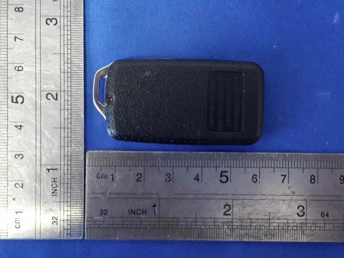
VGA4422
Oct 21, 2015Transmitter(remote control)
Equipment Class
DSC - Part 15 Security/Remote Control Transmitter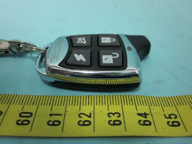
VGA114BP
Aug 01, 2012TRANSMITTER
Equipment Class
DSC - Part 15 Security/Remote Control Transmitter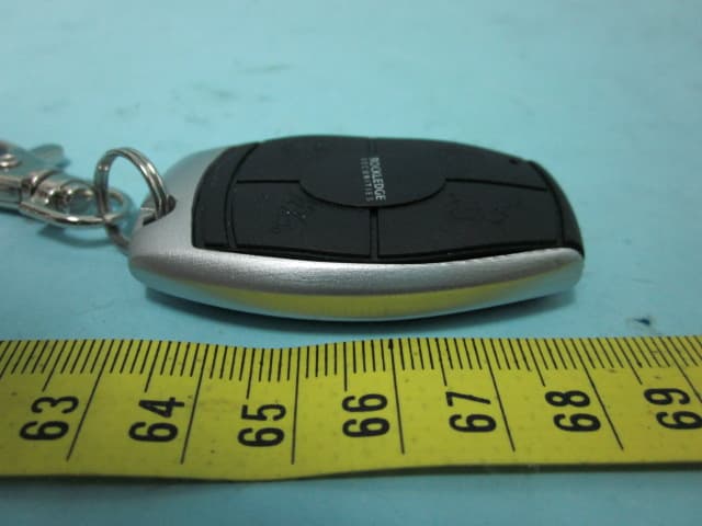
VGAROC4TX
Aug 01, 2012TRANSMITTER
Equipment Class
DSC - Part 15 Security/Remote Control Transmitter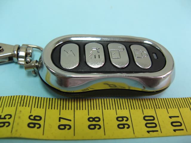
VGA4421
Jul 27, 2011TRANSMITTER
Equipment Class
DSC - Part 15 Security/Remote Control Transmitter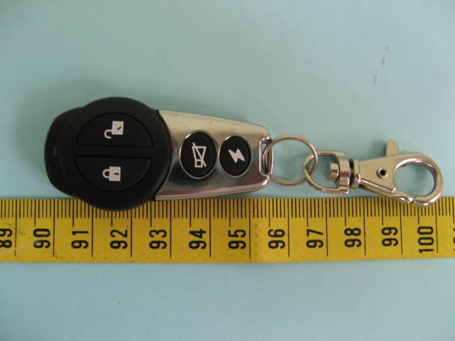
VGA4412
Jul 27, 2011TRANSMITTER
Equipment Class
DSC - Part 15 Security/Remote Control Transmitter