VGWHEI-18YWireless Belt Worn Microphone
BANKEN CO., LTD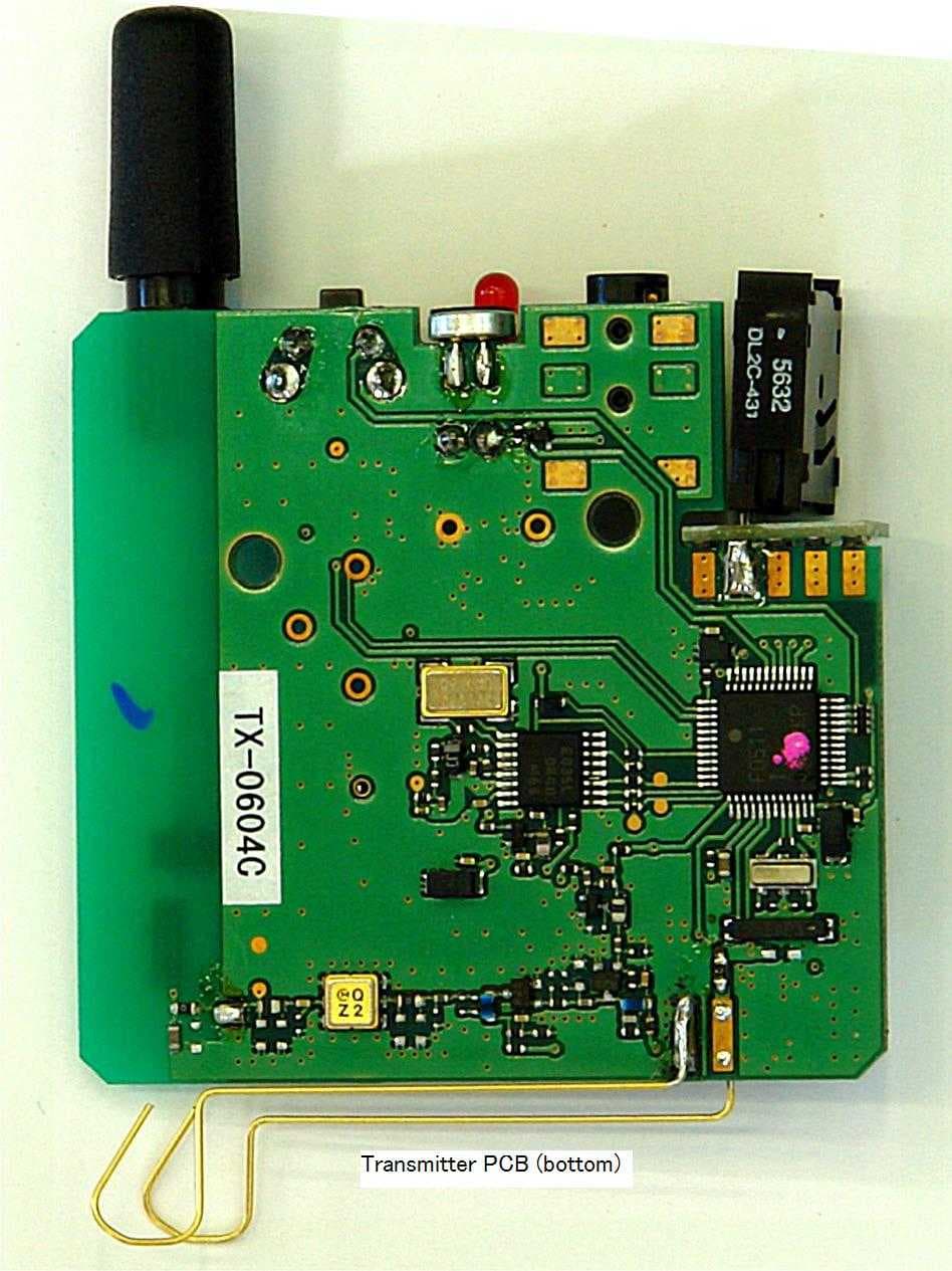
Click to zoom
Application Details
- Equipment Class
- TNT - Licensed Non-Broadcast Transmitter Worn on Body
- Date of Grant
- Oct 09, 2007
- Application Purpose
- Original Equipment
- Date of Application
- Oct 03, 2007
- Equipment Note
- Wireless Belt Worn Microphone
- Frequency Range
- 802.00000000 - 803.80000000
- Company
- BANKEN CO., LTD
- Country
- Japan
Documents & Files
Document Text
Text extracted from the exhibit documents filed with the FCC. Open a document above to read the original.
Users Manual
- 1 - Tour Mic Instructions Transmitter Receiver I. Precautions when using Caution: • To prevent the electromagnetic wave from influencing medical equipment, make sure to switch off the unit's power when placing it in close proximity to the medical equipment. • Changes or modifications not expressly approved by the party responsible for compliance could void the user's authority to operate the equipment. 1. Batteries Black Button slid from the Body Battery Case ( AAA x 2) - 2 - (1) How to open the battery case As pushing up the black button on the side, slide the battery case horizontally from the body. Snap the battery case open by the upside. (2) Dry cell batteries Size AAA alkaline batteries When mounting replacement batteries, be sure not to mistake the polarity. If the polarity is reversed, the battery will discharge all at once and may be incapable of being reused. (3) Battery life should be about 20 hours if used continuously. (4) This model has functions to extend battery life and device for not used continuously. (5) When the battery power gets low, the LED lamp flashes to let you know it's time to change the batteries. (6) If there is a strange noise on the receiver side or if the majority of the receivers are hard to hear, replace the batteries of the transmitter or check if the plug is loose or there is dust in the jack. 2. Transmitter/receiver operation Transmitter Receiver (1) Power on Lightly pressing the power button of the transmitter/receiver turns the power on and lights the red LED lamp. (At first, gradually increase the volume with the volume knob.) At this status, the transmitter/receiver is working normally. (2) Standby mode Transmitter: If there is no communication for approximately 20 seconds, the LED lamp goes off and the equipment switches to "standby mode." Receiver: Linked with the transmitter, and change into “standby mode” immediately. (Applying for a patent) The LED lamp goes off (but power is not cut off). When in "standby mode," when a call is initiated by the transmitter side, the LED lamps of both the - 3 - transmitter and receiver light and communication commences automatically. (It may take about 1 second for communication to commence.) If you press and hold the power of both the transmitter and receiver for several seconds, the LED lamp flashes and the power is shut off. (2) Active mode When the transmitter detects voice input, the receiver is switched to standby mode automatically and starts communication – the receiver is linked with the transmitter. The transmitter/receiver can be reset by pressing the on/off switch for no more than 1 second. (3) The device has 10 channels (0 - 9CH). Set both the receiver and transmitter to the same channel when using. If the lines are crossed, try another channel. (See the following precautions when selecting/switching channels with the channel selector.) (4) When plugging the microphone in the microphone jack of the transmitter and earphones in the earphone jack of the receiver, be sure to insert all the way. If not inserted all the way, you will not be able to transmit/receive properly. (5) Noise may be produced if the plug or jack is dirty. If so, wipe away dirt from the plug and jack with a soft cloth, etc. (if used in areas where there is a lot of sand or dust) (6) Stretch out the microphone cord and earphone cord when using. (7) The transmitter microphone cord and the receiver earphone cord break easily. Be careful when handling the cords. (8) Signals may get mixed with the frequency of local broadcasting stations in small areas. If so, transmission/reception may be temporarily interrupted. Using a cellular telephone in the immediate vicinity may produce noise. This does not however indicate equipment failure. Try a different location. 3. Standby mode (1) If there is no voice communication for approximately 20 seconds, the equipment is designed to switch to standby mode in order to extend the life of the batteries. When the transmitter switches to standby mode, the receiver being used also automatically switches to standby mode and stands by to receive a transmission from the channel that had be used up to that point. - 4 - (2) Standby mode is when the equipment becomes dormant without the power being cut off completely; the equipment uses minimal power while waiting for transmission/reception. (3) Functions in the standby mode are as follows: The receiver waits for a transmission from the transmitter. (The frequency of the current channel is used. If the channel is changed, the transmission cannot be received.) The LED lamps of both the transmitter and receiver go off (but power is not cut off). (4) When a radio wave of the frequency of the channel that had been used up to then is transmitted from the transmitter side, the receiver automatically begins receiving, all function restart and the LED lamp lights. (5) Important The microphone regards not only audio signals as signals; it regards all signals including noise and scratching sounds as signals. The equipment is therefore programmed so that the circuit does not re-open unless you talk for a relatively long period of time (about 1 second). You should note that the initial word is not transmitted. 4. Auto power off function This is a function for saving electricity, and is a measure for when you forgot to turn power off. Transmitter: If nothing is inputted for approximately an hour, the auto power off function is actuated, and the power of both the transmitter and receiver is cut off. Receiver: If transmitter does not send signal for approximately an hour, the auto power off function is actuated, and the power of both the transmitter and receiver is cut off. In this state, both the transmitter and the receiver do not go back to “active mode,” automatically. Turn the power back on by pressing the power switch (no more than 1 second). 5. Other precautions when using (1) No exposure to water The equipment is not water-proof. If it gets wet from drops of w…
Text truncated - open the document above for the full version.
Cover Letter(s)
RE: Seiden Electric Engineering Co., Ltd FCC ID: VGWHEI-18Y 1.) You have requested the Internal Photographs be held Confidential. In general, this Exhibit cannot be held Confidential without substantial justification. In my opinion, this requirement has not been met .Please provide a detailed rationale why Internal Photographs should be held Confidential. Answer: We accept that the pictures could be shown on the FCC website and therefore should not be considered as confidential information. 2.) Please do a final double-check on the model numbers. There seems to be instances where moth “...18Y” and “...18YT” are confused. Kindly do one last double check of your Exhibits. Answer: We have corrected the typos and the terminology of the product is 18YT. Please refer to the uploaded manual, operation description and label. 3.) Please note that the FCC logo is not appropriate for this device. Only computers and computer peripherals which follow the DoC equipment authorization procedures are to use this mark. Answer: The label has been corrected and uploaded. 4.) Please provide a tune-up procedure. This is required for all Licensed radio transmitters. Answer: No tune-up is required please find uploaded the cover letter form the client. 5.) Please note that your test procedure of 1.9.2 is in error. Only the TIA/EIA 603 substitution method is recognized by FCC for this test. Answer: We are taking note of your comment. 6.) The conducted spurious emissions test of 1.9.3 does not appear to follow the resolution bandwidth descriptions listed in TIA/EIA 603. Please address. Answer: The correct setting was not described on the test report. Please find the uploaded test report with the correct information. 7.) What units would you like to show the RF power? Would you like to use Conducted or ERP values? Please note the 731 form does not indicate. Answer: the 731 Form has been updated. The ERP value has been described on this form. 8.) Please provide an emission designator complete with necessary bandwidth on Form 731. Please provide a requested frequency tolerance on Form 731 too. Answer: the 731 Form has been updated. 9.) Please provide the voltage and current through the final amplification stage as required under Part 2 of the Rules. If I have missed it, my apologies – please help me find it. Answer: The information has been placed on the operation description. Please refer to the uploaded operation description.
Cover Letter(s)
American Telecommunications Certification Body Inc. 6731 Whittier Ave, McLean, VA 22101 September 14, 2007 RE: Seiden Electric Engineering Co., Ltd FCC ID: VGWHEI-18Y I have a few comments on this Application. Depending on your responses, kindly understand there may be additional comments. 1.) You have requested the Internal Photographs be held Confidential. In general, this Exhibit cannot be held Confidential without substantial justification. In my opinion, this requirement has not been met .Please provide a detailed rationale why Internal Photographs should be held Confidential. 2.) Please do a final double-check on the model numbers. There seems to be instances where moth “...18Y” and “...18YT” are confused. Kindly do one last double check of your Exhibits. 3.) Please note that the FCC logo is not appropriate for this device. Only computers and computer peripherals which follow the DofC equipment authorization procedures are to use this mark. 4.) Please provide a tune-up procedure. This is required for all Licensed radio transmitters. 5.) Please note that your test procedure of 1.9.2 is in error. Only the TIA/EIA 603 substitution method is recognized by FCC for this test. 6.) The conducted spurious emissions test of 1.9.3 does not appear to follow the resolution bandwidth descriptions listed in TIA/EIA 603. Please address. 7.) What units would you like to show the RF power? Would you like to use Conducted or ERP values? Please note the 731 form does not indicate. 8.) Please provide an emission designator complete with necessary bandwidth on Form 731. Please provide a requested frequency tolerance on Form 731 too. 9.) Please provide the voltage and current through the final amplification stage as required under Part 2 of the Rules. If I have missed it, my apologies – please help me find it. William H. Graff President mailto: [email protected] The items indicated above must be submitted before processing can continue on the above referenced application. Failure to provide the requested information may result in application termination. Correspondence should be considered part of the permanent submission and may be viewed from the Internet after a Grant of Equipment Authorization is issued. Please do not respond to this correspondence using the email reply button. In order for your response to be processed expeditiously, you must submit your documents through the AmericanTCB.com website. Also, please note that partial responses increase processing time and should not be submitted. Any questions about the content of this correspondence should be directed to the sender.
Internal Photos
Transmitter PCB(top) without shield case Close-up photo of the circuit (inside of the shield case)
Test Report
JAPAN QUALITY ASSURANCE ORGANIZATION 21-25, KINUTA 1-CHOME, SETAGAYA-KU, TOKYO 157-8573 JAPAN PHONE (03) 3416-0111, JQA J FAX (03) 3416-9691 JQA File No. : 400-70128 Issue Date : August 17, 2007 Page 1 of 42 EMI TEST REPORT JQA File No. : 400-70128 Model No. : HEI-18YT Type of Equipment : Tour Mic(Transmitter) Regulations Applied : CFR 47 FCC Rules and Regulations Part 74 FCC ID : VGWHEI-18Y Applicant : Seiden Electric Engineering Co., Ltd. Address : 1842-10 Kimagase, Noda-shi, Chiba-ken, 270-0222 Japan Manufacturer : Seiden Electric Engineering Co., Ltd. Address : 1842-10 Kimagase, Noda-shi, Chiba-ken, 270-0222 Japan Received date of EUT : May 19, 2007 Test Result : Passed Test results in this report are obtained in use of equipment that is traceable to National Institute of Advanced Industrial Science and Technology (AIST) of Japan and Communication Research Laboratory (CRL) of Japan. The test results only respond to the tested sample. This report should not be reproduced except in full, without the written approval of JQA EMC Engineering Dept. Testing Div. JQA File No. :400-70128 FCC ID :VGWHEI-18Y Model No. :HEI-18YT Issue Date :August 17, 2007 Standard :CFR 47 FCC Rules Part 74 Page 2 of 42 TABLE OF CONTENTS Page 1 Documentation 1.1 Test Regulation 3 1.2 General Information 3 1.3 Test Condition 4 – 6 1.4 EUT Modifications / Deviation from Standard 7 1.5 Test results 8 1.6 Summary 9 1.7 Test Configuration / Operation of EUT 10 1.8 EUT Arrangement(Drawing) 11 1.9 Preliminary Test and Test-setup (Drawings) 12 – 18 1.10 EUT Arrangement (Photographs) 19 - 20 2 Test Data 2.1 RF Power Output 21 2.2 Modulation Characteristics 22 – 28 2.3 Radiated Emissions 29 – 31 2.4 Conducted Emissions 32 2.5 Occupied Bandwidth 33 – 36 2.6 Frequency Stability 37 - 38 3 Appendix Test instruments List 39 – 42 JQA File No. :400-70128 FCC ID :VGWHEI-18Y Model No. :HEI-18YT Issue Date :August 17, 2007 Standard :CFR 47 FCC Rules Part 74 Page 3 of 42 1 DOCUMENTATION 1.1 TEST REGULATION FCC Rules and Regulations Part 74 Subpart H Low Power Auxiliary Stations Test procedure : RF power output, modulation characteristics, occupied bandwidth, field strength of spurious radiation and frequency stability tests were performed according to the procedures in FCC Rules and Regulations Part 2. 1.2 GENERAL INFORMATION 1.2.1 Test facility : 1) Test Facility located at EMC Engineering Dept. Testing Div. : - No.2 and 3 Anechoic Chambers(3 meters Site). - Shielded Enclosure. 2) EMC Engineering Dept. Testing Div. is accredited under the National Voluntary Laboratory accreditation Program for satisfactory compliance established in title 15, Part 285 Code of Federal Regulations. NVLAP Lab Code : 200189-0 (Effective through : June 30, 2008) 1.2.2 Description of the Equipment Under Test (EUT) : 1) Type of Equipment : Tour Mic(Transmitter) 2) Product Type : Prototype 3) Category : Licensed Non-Broadcast Transmitter Worn On Body 4) EUT Authorization : Certification 5) FCC ID : VGWHEI-18Y 6) Trade Name : None 7) Model No. : HEI-18YT 8) Operating Frequency Range : 802.000 MHz – 803.800 MHz 9) Highest Frequency Used in the EUT : 803.800 MHz 10) Necessary Bandwidth : 20 kHz (=2M+2D) (M: Maximum modulation = 3 kHz D: Peak frequency deviation = 7 kHz) * Peak frequency deviation is designed by manufacturer. 11) RF Output Power : 8.5 mW (Manufacturer defined) 12) Emission Designator : 20KF3E 13) Serial No. : None 14) Date of Manufacture : None 15) Power Rating : DC 3.0V(Battery) 16) EUT Grounding : None 1.2.3 Definitions for symbols used in this test report : x - indicates that the listed condition, standard or equipment is applicable for this report. - indicates that the listed condition, standard or equipment is not applicable for this report. JQA File No. :400-70128 FCC ID :VGWHEI-18Y Model No. :HEI-18YT Issue Date :August 17, 2007 Standard :CFR 47 FCC Rules Part 74 Page 4 of 42 1.3 TEST CONDITION 1.3.1 The measurement of the RF power output the Radiated Emission(30 MHz – 1000 MHz) x - was performed in the following test site. - was not applicable. Test location : Safety & EMC Center EMC Engineering Dept. Testing Div. 21-25, Kinuta 1-chome, Setagaya-ku, Tokyo 157-8573, Japan x - Anechoic Chamber A (3 meters) - Anechoic Chamber B (3 meters) Validation of Site Attenuation : 1) Last Confirmed Date :March, 2007 2) Interval :1 year Used test instruments : Type Number of test instruments (Refer to Appendix) Test Receiver 11 Cable 38 Antenna 22, 24, 26, 28 RF Amplifier N/A Signal Generator 62 Power Meter 65 Power Sensor 66 JQA File No. :400-70128 FCC ID :VGWHEI-18Y Model No. :HEI-18YT Issue Date :August 17, 2007 Standard :CFR 47 FCC Rules Part 74 Page 5 of 42 1.3.2 The measurement of the Radiated Emission(Above 1000 MHz) x - was performed in the following test site. - was not applicable. Test location : Safety & EMC Center EMC Engineering Dept. Testing Div. 21-25, Kinuta 1-chome, Setagaya-ku, Tokyo 157-8573, Japan x - Anechoic Chamber A (3 meters) - Anechoic Chamber B (3 meters) Validation of Site Attenuation : 1) Last Confirmed Date :March, 2007 2) Interval :1 year Used test instruments : Type Number of test instruments (Refer to Appendix) Test Receiver 13 Spectrum Analyzer N/A Cable 46, 195 Antenna 31 RF Amplifier 57 Band Reject Filter N/A High Pass Filter N/A 1.3.3 The measurement of the Conducted Spurious Emission x - was performed in the following test site. - was not applicable. Used test instruments : Type Number of test instruments (Refer to Appendix) Test Receiver N/A Spectrum Analyzer 13 Cable 45 Attenuator 80 RF Amplifier N/A Signal Generator 62 JQA File No. :400-70128 FCC ID :VGWHEI-18Y Model No. :HEI-18YT Issue Date :August 17, 2007 Standard :CFR 47 FCC Rules Part 74 Page 6 of 42 1.3.4 The measurement of the Modulation Characteristics and the Occupied Bandwidth x - was performed. - was not applicable. Used test instruments : Type Number of test instruments (Refer to Appendix) Test Receiver 13 Spectrum Analyzer N/A Function Generator 5…
Text truncated - open the document above for the full version.
Contact Information
Applicant
Fumio Nishikawa(Managing Director)
Technical Contact
TUV Rheinland Japan Ltd.Rachid Sehb
+81 92 845 5358
Global Technology Assessment Center · Japan
Test Firm
Japan Quality Assurance Org.Katsumi Nishii
Technical Specifications
| # | Rule Parts | Frequency Range | Power Output | Emission | Tolerance |
|---|---|---|---|---|---|
| 1 | 74 | 802 MHz - 803.8 MHz | 2.60 mW | 20K0F3E | 0.0008000000 % |
Other Applications from BANKEN CO., LTD

VGWHEI-25Y
Jul 31, 2013TOUR de GUIDE 800
Equipment Class
DXX - Part 15 Low Power Communication Device Transmitter
VGWHEI-23Y-1
Nov 08, 2012TOUR de GUIDE
Equipment Class
DTS - Digital Transmission System
VGWHEI-18Y-1
Feb 28, 2011One Way Transceiver Guide System
Equipment Class
DXX - Part 15 Low Power Communication Device Transmitter