VGWHEI-18Y-1One Way Transceiver Guide System
BANKEN CO., LTD
Click to zoom
Application Details
- Equipment Class
- DXX - Part 15 Low Power Communication Device Transmitter
- Date of Grant
- Feb 28, 2011
- Application Purpose
- Original Equipment
- Date of Application
- Feb 28, 2011
- Equipment Note
- One Way Transceiver Guide System
- Frequency Range
- 920.20000000 - 922.00000000
- Company
- BANKEN CO., LTD
- Country
- Japan
Documents & Files
Document Text
Text extracted from the exhibit documents filed with the FCC. Open a document above to read the original.
Users Manual
1 Tour Mic/HEI-18Y-1 Instructions Transmitter Receiver I. Precautions when using Caution: x To prevent the electromagnetic wave from influencing medical equipment, make sure to switch off the unit's power when placing it in close proximity to the medical equipment. x Changes or modifications not expressly approved by the party responsible for compliance could void the user's authority to operate the equipment. 1. Batteries Black Buttonslid from the Body Battery Case ( AAA x 2) 2 (1) How to open the battery case As pushing up the black button on the side, slide the battery case horizontally from the body. Snap the battery case open by the upside. (2) Dry cell batteries Size AAA alkaline batteries When mounting replacement batteries, be sure not to mistake the polarity. If the polarity is reversed, the battery will discharge all at once and may be incapable of being reused. (3) Battery life should be about 20 hours if used continuously. (4)This model has functions to extend battery life and device for not used continuously. (5)When the battery power gets low, the LED lamp flashes to let you know it's time to change the batteries. (6)If there is a strange noise on the receiver side or if the majority of the receivers are hard to hear, replace the batteries of the transmitter or check if the plug is loose or there is dust in the jack. 2. Transmitter/receiver operation Transmitter Receiver (1) Power on Lightly pressing the power button of the transmitter/receiver turns the power on and lights the red LED lamp. (At first, gradually increase the volume with the volume knob.) At this status, the transmitter/receiver is working normally. (2) Standby mode Transmitter: If there is no communication for approximately 20 seconds, the LED lamp goes off and the equipment switches to "standby mode." Receiver: Linked with the transmitter, and change into “standby mode” immediately. (Applying for a patent)The LED lamp goes off (but power is not cut off). When in "standby mode," when a call is initiated by the transmitter side, the LED lamps of both the 3 transmitter and receiver light and communication commences automatically. (It may take about 1 second for communication to commence.) If you press and hold the power of both the transmitter and receiver for several seconds, the LED lamp flashes and the power is shut off. (2) Active mode When the transmitter detects voice input, the receiver is switched to standby mode automatically and starts communication – the receiver is linked with the transmitter. The transmitter/receiver can be reset by pressing the on/off switch for no more than 1 second. (3) The device has 10 channels (0 - 9CH). Set both the receiver and transmitter to the same channel when using. If the lines are crossed, try another channel. (See the following precautions when selecting/switching channels with the channel selector.) (4) When plugging the microphone in the microphone jack of the transmitter and earphones in the earphone jack of the receiver, be sure to insert all the way. If not inserted all the way, you will not be able to transmit/receive properly. (5) Noise may be produced if the plug or jack is dirty. If so, wipe away dirt from the plug and jack with a soft cloth, etc. (if used in areas where there is a lot of sand or dust) (6) Stretch out the microphone cord and earphone cord when using. (7) The transmitter microphone cord and the receiver earphone cord break easily. Be careful when handling the cords. (8) Signals may get mixed with the frequency of local broadcasting stations in small areas. If so, transmission/reception may be temporarily interrupted. Using a cellular telephone in the immediate vicinity may produce noise. This does not however indicate equipment failure. Try a different location. 3. Standby mode (1) If there is no voice communication for approximately 20 seconds, the equipment is designed to switch to standby mode in order to extend the life of the batteries. When the transmitter switches to standby mode, the receiver being used also automatically switches to standby mode and stands by to receive a transmission from the channel that had be used up to that point. 4 (2) Standby mode is when the equipment becomes dormant without the power being cut off completely; the equipment uses minimal power while waiting for transmission/reception. (3) Functions in the standby mode are as follows: The receiver waits for a transmission from the transmitter. (The frequency of the current channel is used. If the channel is changed, the transmission cannot be received.) The LED lamps of both the transmitter and receiver go off (but power is not cut off). (4) When a radio wave of the frequency of the channel that had been used up to then is transmitted from the transmitter side, the receiver automatically begins receiving, all function restart and the LED lamp lights. (5) Important The microphone regards not only audio signals as signals; it regards all signals including noise and scratching sounds as signals. The equipment is therefore programmed so that the circuit does not re-open unless you talk for a relatively long period of time (about 1 second). You should note that the initial word is not transmitted. 4. Auto power off function This is a function for saving electricity, and is a measure for when you forgot to turn power off. Transmitter: If nothing is inputted for approximately an hour, the auto power off function is actuated, and the power of both the transmitter and receiver is cut off. Receiver: If transmitter does not send signal for approximately an hour, the auto power off function is actuated, and the power of both the transmitter and receiver is cut off. In this state, both the transmitter and the receiver do not go back to “active mode,” automatically. Turn the power back on by pressing the power switch (no more than 1 second). 5. Other precautions when using (1) No exposure to water The equipment is not water-proof. If it gets wet from drops of water, etc.,…
Text truncated - open the document above for the full version.
Cover Letter(s)
VERIFICATION Report No.: NEI-FCCE-1-R1006002 Issued Date: Jan. 06, 2010 This is to certify that the product listed in follows was (were) tested in the Neutron EMC Laboratory to comply with the criteria limits Class B of conducted and radiated emissions of the Technical Standards FCC Part 15, Subpart B, established by the FCC, USA. Equipment One Way Transceiver Guide System Model Name HEI-18Y-1 Brand Name Tour Mic Applicant BANKEN CO., LTD Address 1842-10 Kimagase, Noda-shi, Chiba-kan, 270-0222 Japan Measurement ANSI C 63.4 (2003) Method CISPR 22: 2005 +A1: 2005 ICES-003: 2004 The test data, data evaluation, and equipment configuration contained in our test report (Report No. NEI-FCCE-1-R1006002) were obtained utilizing the test procedures, test instruments, test sites that has been accredited by the Authority of NVLAP and TAF according to the ISO-17025 quality assessment standard and technical standard(s). The test data contained in the referenced test report relate only to the EUT sample and item(s) tested. Andy Chiu Authorized Signatory Neutron Engineering Inc. B1, No. 37, Lane 365, YangGuang St., NeiHu District 114, Taipei, Taiwan. TEL: +886-2-2657-3299 FAX: +886-2-2657-3331
External Photos
RV-0000000 Project No.: R1006002 Page 2 of 23 Neutron Engineering Inc. Transmitter Part (MIC) R1006002 R1006002 RV-0000000 Project No.: R1006002 Page 3 of 23 Neutron Engineering Inc. R1006002 R1006002 RV-0000000 Project No.: R1006002 Page 4 of 23 Neutron Engineering Inc. R1006002 RV-0000000 Project No.: R1006002 Page 12 of 23 Neutron Engineering Inc. R1006002 RV-0000000 Project No.: R1006002 Page 13 of 23 Neutron Engineering Inc. Receiver Part (PHONE) R1006002 R1006002 RV-0000000 Project No.: R1006002 Page 14 of 23 Neutron Engineering Inc. R1006002 R1006002 RV-0000000 Project No.: R1006002 Page 15 of 23 Neutron Engineering Inc. R1006002 RV-0000000 Project No.: R1006002 Page 23 of 23 Neutron Engineering Inc. R1006002
Internal Photos
RV-0000000 Project No.: R1006002 Page 16 of 23 Neutron Engineering Inc. R1006002 R1006002 RV-0000000 Project No.: R1006002 Page 17 of 23 Neutron Engineering Inc. R1006002 R1006002 RV-0000000 Project No.: R1006002 Page 18 of 23 Neutron Engineering Inc. R1006002 R1006002 RV-0000000 Project No.: R1006002 Page 19 of 23 Neutron Engineering Inc. R1006002 R1006002 RV-0000000 Project No.: R1006002 Page 20 of 23 Neutron Engineering Inc. R1006002 R1006002 RV-0000000 Project No.: R1006002 Page 21 of 23 Neutron Engineering Inc. R1006002 R1006002 RV-0000000 Project No.: R1006002 Page 22 of 23 Neutron Engineering Inc. R1006002 R1006002
Internal Photos
RV-0000000 Project No.: R1006002 Page 5 of 23 Neutron Engineering Inc. R1006002 R1006002 RV-0000000 Project No.: R1006002 Page 6 of 23 Neutron Engineering Inc. R1006002 R1006002 RV-0000000 Project No.: R1006002 Page 7 of 23 Neutron Engineering Inc. R1006002 R1006002 RV-0000000 Project No.: R1006002 Page 8 of 23 Neutron Engineering Inc. R1006002 R1006002 RV-0000000 Project No.: R1006002 Page 9 of 23 Neutron Engineering Inc. R1006002 R1006002 RV-0000000 Project No.: R1006002 Page 10 of 23 Neutron Engineering Inc. R1006002 R1006002 RV-0000000 Project No.: R1006002 Page 11 of 23 Neutron Engineering Inc. R1006002
Test Report
RV-0000000 Report No.: NEI-FCCP-1-R1006002 Page 1 of 29 Neutron Engineering Inc. Radio Test Report FCC ID: VGWHEI-18Y-1 Issued Date : Jan. 07, 2010 Project No. : R1006002 Equipment : One Way Transceiver Guide System Model Name : HEI-18Y-1 Applicant : BANKEN CO., LTD Address : 1842-10 Kimagase, Noda-shi, Chiba-kan, 270-0222 Japan Tested by: Neutron Engineering Inc. EMC Laboratory Date of Receipt: Jun. 08, 2010 Date of Test: Jun. 08, 2010 ~ Dec. 30, 2010 Testing Engineer : (Gary Chou) Technical Manager : (Jeff Yang) Authorized Signatory : (Andy Chiu) Neutron Engineering Inc. B1, No. 37, Lane 365, YangGuang St., NeiHu District 114, Taipei, Taiwan. TEL: +886-2-2657-3299 FAX: +886-2-2657-3331 RV-0000000 Report No.: NEI-FCCP-1-R1006002 Page 2 of 29 Neutron Engineering Inc. Declaration Neutron represents to the client that testing is done in accordance with standard procedures as applicable and that test instruments used has been calibrated with the standards traceable to National Measurement Laboratory (NML) of R.O.C., or National Institute of Standards and Technology (NIST) of U.S.A. Neutron's reports apply only to the specific samples tested under conditions. It is manufacture’s responsibility to ensure that additional production units of this model are manufactured with the identical electrical and mechanical components. Neutron shall have no liability for any declarations, inferences o r generalizations drawn by the client or others from Neutron issued reports. Neutron’s reports must not be used by the client to claim product endorsement by the authorities or any agency of the Government. This report is the confidential property of the client. As a mutual protection to the clients, the public and Neutron-self, extracts from the test report shall not be reproduced except in full with Neutron’s authorized written approval. Neutron’s laboratory quality assurance procedures are in compliance with the ISO Guide 17025 requirements, and accredited by the conformity assessment authorities listed in this test report. Limitation For the use of the authority's logo is limited unless the Test Standard(s)/Scope(s)/Item(s) mentioned in this test report is (are) included in the conformity assessment authorities acceptance respective. RV-0000000 Report No.: NEI-FCCP-1-R1006002 Page 3 of 29 Neutron Engineering Inc. Table of Contents Page 1 . CERTIFICATION 4 2 . SUMMARY OF TEST RESULTS 5 2.1 TEST FACILITY 6 2.2 MEASUREMENT UNCERTAINTY 6 3 . GENERAL INFORMATION 7 3.1 GENERAL DESCRIPTION OF EUT 7 3.2 DESCRIPTION OF TEST MODES 8 3.3 BLOCK DIAGRAM SHOWING THE CONFIGURATION OF SYSTEM TESTED 9 3.4 DESCRIPTION OF SUPPORT UNITS 10 4 . EMC EMISSION TEST 11 4.1 RADIATED EMISSION MEASUREMENT 11 4.1.1 LIMITS OF RADIATED EMISSION MEASUREMENT 11 4.1.2 MEASUREMENT INSTRUMENTS LIST 12 4.1.3 TEST PROCEDURE 12 4.1.4 DEVIATION FROM TEST STANDARD 12 4.1.5 TEST SETUP 13 4.1.6 EUT OPERATING CONDITIONS 14 4.1.7 TEST RESULTS-BETWEEN 30MHZ AND 1000MHZ 15 4.1.8 TEST RESULTS- FUNDAMENTAL FREQUENCY & ABOVE 1000MHZ 17 5 . EUT TEST PHOTO 29 RV-0000000 Report No.: NEI-FCCP-1-R1006002 Page 4 of 29 Neutron Engineering Inc. 1. CERTIFICATION E q u i p m e n t : One Way Transceiver Guide System Brand Name : Tour Mic Model Name : HEI-18Y-1 A p p l i c a n t : BANKEN CO., LTD Date of Test : Jun. 08, 2010 ~ Dec. 30, 2010 Standards : FCC Part15, Subpart C(15.249) / ANCI C63.4: 2003 The above equipment has been tested and found compliance with the requirement of the relative standards by Neutron Engineering Inc. EMC Laboratory. The test data, data evaluation, and equipment configuration contained in our test report (Ref No. NEI-FCCP-1-R1006002) were obtained utilizing the test procedures, test instruments, test sites that has been accredited by the Authority of NVLAP and TAF according to the ISO-17025 quality assessment standard and technical standard(s). RV-0000000 Report No.: NEI-FCCP-1-R1006002 Page 5 of 29 Neutron Engineering Inc. 2. SUMMARY OF TEST RESULTS Test procedures according to the technical standards: FCC Part15, Subpart C Standard Section Test Item Judgment Remark 15.207 Conducted Emission N/A 15.249 Radiated Spurious Emission PASS NOTE: (1) ” N/A” denotes test is not applicable in this Test Report. RV-0000000 Report No.: NEI-FCCP-1-R1006002 Page 6 of 29 Neutron Engineering Inc. 2.1 TEST FACILITY The test facilities used to collect the test data in this report: CB08: (VCCI RN: G-91; FCC RN: 614388; FCC DN: TW1054; IC Assigned Code: 4428C-1) 1F., No. 61, Ln. 77, Sing-ai Rd., Neihu Dist., Taipei City 114, Taiwan (R.O.C.) 2.2 MEASUREMENT UNCERTAINTY The reported uncertainty of measurement y ± U,where expended uncertainty U is based on a standard uncertainty multiplied by a coverage factor of k=2,providing a level of confidence of approximately 95%. The measurement instrumentation uncertainty considerations contained in CISPR 16-4-2. Test Site Item Measurement Frequency Range Uncertainty NOTE 30 - 200MHz 3.35 dB 200 - 1000MHz 3.11 dB 1 - 18GHz 3.97 dB Horizontal Polarization 18 - 40GHz 4.01 dB 30 - 200MHz 3.22 dB 200 - 1000MHz 3.24 dB 1 - 18GHz 4.05 dB CB08 Radiated Emission at 3m Vertical Polarization 18 - 40GHz 4.04 dB Our calculated Measurement Instrumentation Uncertainty is shown in the tables above. These are our U lab values in CISPR 16-4-2 terminology. Since Table 1 of CISPR 16-4-2 has values of measurement instrumentation uncertainty, called U CISPR , as follows: Conducted Disturbance (mains port) – 150 kHz – 30 MHz : 3.6 dB Radiated Disturbance (electric field strength on an open area test site or alternative test site) – 30 MHz – 1000 MHz : 5.2 dB It can be seen that our U lab values are smaller than U CISPR . RV-0000000 Report No.: NEI-FCCP-1-R1006002 Page 7 of 29 Neutron Engineering Inc. 3. GENERAL INFORMATION 3.1 GENERAL DESCRIPTION OF EUT Equipment One Way Transceiver Guide System Brand Name Tour Mic Model Name HEI-18Y-1 OEM Brand/Model Name N/A Model Difference The EUT contains two parts: Transmitter Part (MIC) and Receive…
Text truncated - open the document above for the full version.
Test Setup Photos
RV-0000000 Report No.: NEI-FCCP-1-R1006002 Page 29 of 29 Neutron Engineering Inc. 5. EUT TEST PHOTO Radiated Measurement Photos
Contact Information
Applicant
Fumio Nishikawa(Managing Director)
Technical Contact
Neutron Engineering Inc.Kate Lin
[email protected]+886-2-2646-5426
B1, No. 37, Lane 365, YangGang St., · Taipei · Taiwan
Test Firm
BTL Inc.Andy Yeh
Technical Specifications
| # | Rule Parts | Frequency Range | Power Output |
|---|---|---|---|
| 1 | 15C | 920.2 MHz - 922 MHz | - |
Other Applications from BANKEN CO., LTD

VGWHEI-25Y
Jul 31, 2013TOUR de GUIDE 800
Equipment Class
DXX - Part 15 Low Power Communication Device Transmitter
VGWHEI-23Y-1
Nov 08, 2012TOUR de GUIDE
Equipment Class
DTS - Digital Transmission System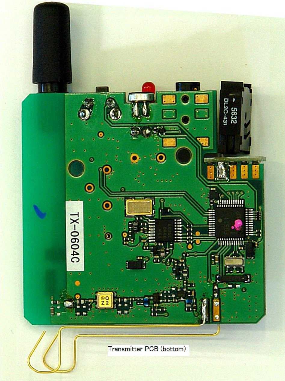
VGWHEI-18Y
Oct 09, 2007Wireless Belt Worn Microphone
Equipment Class
TNT - Licensed Non-Broadcast Transmitter Worn on Body