VIDCENTRONElectric Meter with Transceiver
Arad Technologies Ltd.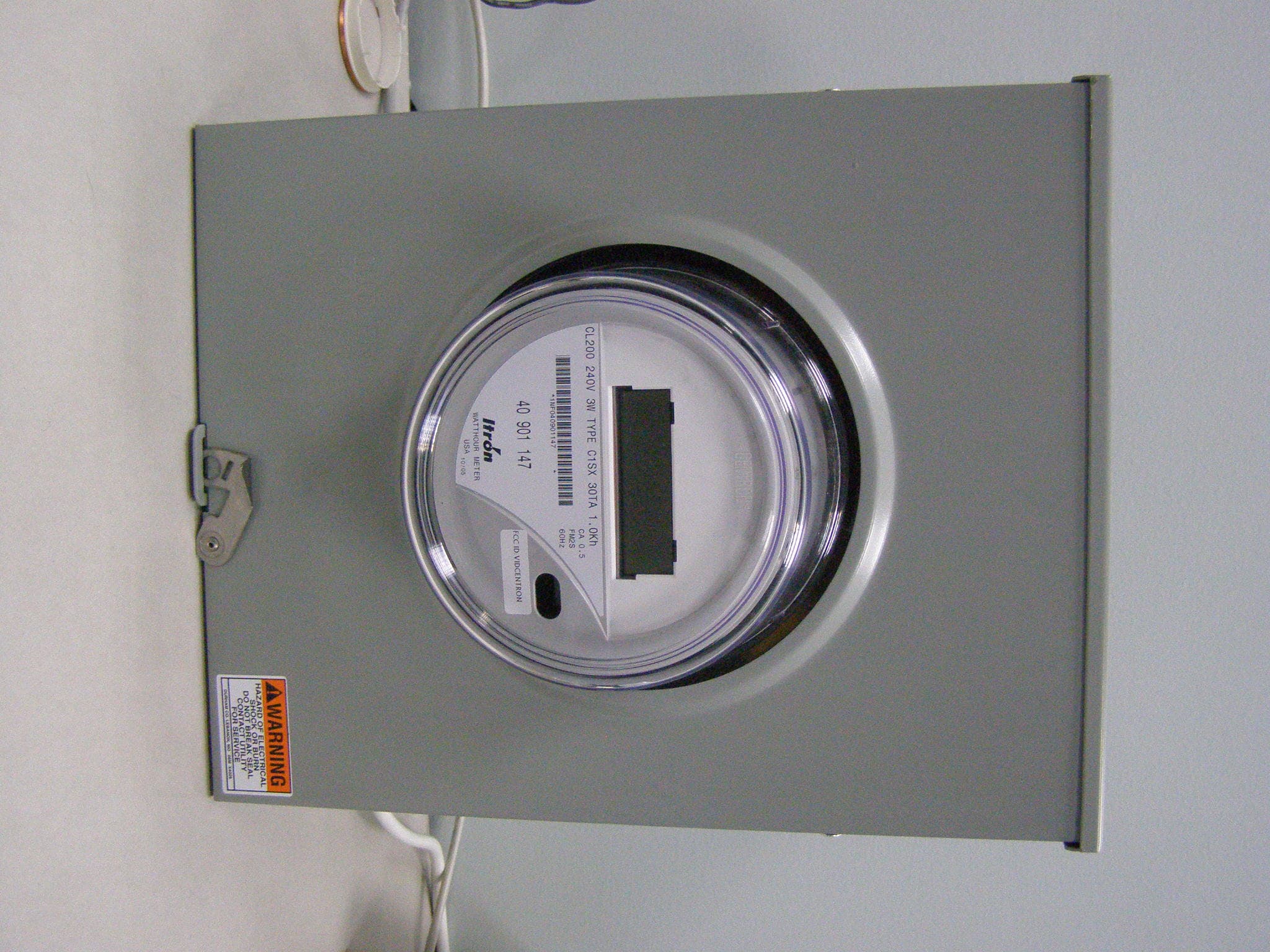
Click to zoom
Application Details
- Equipment Class
- DTS - Digital Transmission System
- Date of Grant
- Sep 26, 2007
- Application Purpose
- Original Equipment
- Date of Application
- Sep 25, 2007
- Equipment Note
- Electric Meter with Transceiver
- Frequency Range
- 916.30000000 - 916.30000000
- Company
- Arad Technologies Ltd.
- Country
- Israel
Documents & Files
Document Text
Text extracted from the exhibit documents filed with the FCC. Open a document above to read the original.
Users Manual
MM REV 8/29/2007 .......................................................................................................................................... Master Meter, Inc. - -- - 101 Regency Parkway, Mansfield, TX 76063 www.mastermeter.com Toll Free: 800-765-6518 - -- - Main Line: 817-842-8000 - -- - FAX: 8178428100 [email protected] INSTALLATION INSTRUCTIONS INSTALLATION INSTRUCTIONSINSTALLATION INSTRUCTIONS INSTALLATION INSTRUCTIONS ARAD CENTRON ARAD CENTRONARAD CENTRON ARAD CENTRON ELECTRICITY METER ELECTRICITY METER ELECTRICITY METER ELECTRICITY METER Download manual from Master Meter Web site. http://www.mastermeter.com/en/downloads.html http://www.mastermeter.com/en/downloads.htmlhttp://www.mastermeter.com/en/downloads.html http://www.mastermeter.com/en/downloads.html 17 8428100 FCC ID VIDCENTRON The user and the installer should be aware that changes and modifications to the equipment not expressly approved by Master Meter could void warranty and the user’s authority to operate the equipment. Professionally trained personnel should install the equipment. NOTE: The antenna used for this transmitter must be installed to normally provide minimum separation distance of at least 20 cm from all persons and must not be co-located or operating in conjunction with any other antenna or transmitter For optimum performance • Meter should be installed upright (parallel to the wall) and not on an angle. • Meter should be located at open space or in close box with windows, not in close metal box. indicate 240 volt version FIELD PROGRAMABLE PARAMETERS FIELD PROGRAMABLE PARAMETERSFIELD PROGRAMABLE PARAMETERS FIELD PROGRAMABLE PARAMETERS DEFAULT PARAMETERS DEFAULT PARAMETERSDEFAULT PARAMETERS DEFAULT PARAMETERS USER CODE USER CODEUSER CODE USER CODE 5 DIGITS USER CODE USER CODEUSER CODE USER CODE 0 TRANSMISSION INTERVAL TRANSMISSION INTERVALTRANSMISSION INTERVAL TRANSMISSION INTERVAL 5 DIGITS TRANSMISSION INTERVAL TRANSMISSION INTERVALTRANSMISSION INTERVAL TRANSMISSION INTERVAL 11 second TRANSMISSION TRANSMISSION TRANSMISSION TRANSMISSION OFF/ON TRANSMISSION TRANSMISSIONTRANSMISSION TRANSMISSION ON ATTENTION: ATTENTION:ATTENTION: ATTENTION: The digital portion of the transceiver has been tested and found to comply with the limits for a Class B digital device, pursuant to part 15 of the FCC Rules. These limits are designed to provide reasonable protection against harmful interference in a residential installation. This equipment generates uses and can radiate radio frequency energy and, if not installed and used in accordance with the instructions, may cause harmful interference to radio communications. However, there is no guarantee that interference will not occur in a particular installation. If this equipment does cause harmful interference to radio or television reception, which can be determined by turning the equipment off and on, the user is encouraged to try to correct the interference by one or more of the following measures: 1.) Reorient or relocate the receiving antenna. 2.) Increase the separation between the equipment and receiver. 3.) Connect the equipment into an outlet on a circuit different from that to which the receiver is connected. 4.) Consult the dealer or an experienced radio/TV technician for help. Note: The device (or CENTRON) transmission duty cycle is limited by its design not to exceed 0.12%. This device complies with Part 15 of FCC Rules. Operation is subject to the following two conditions: (1) This device may not cause harmful interference, and (2) this device must accept any interference received, including interference that may cause undesired
Block Diagram
Arad Technologies Proprietary FCC ID: VIDCENTRON August 28, 2007 Page 1 of 1 Block diagram Micro controller Digital Control Logic Clock Generator 32768HZ RF Transmitter RF Receiver LO Clock Generator 26.6353Mhz POWER SOURCE 3.3Vdc Antenna 916.3 MHz 916.3 MHz RxD TxD Tx Control Rx Control PULSES METER BOARD
Cover Letter(s)
Arad Technologies Proprietary Arad Technologies Ltd., Carmel 2, P.O.B 537, Yokneam 20692, Israel Tel: +972-4-9935222 Fax: +972-4-9935227 July 2, 2007 Subject: Letter of Authorization We the undersigned, hereby authorize Hermon Laboratories to act on our behalf in all manners relating to application for equipment authorization, including signing of all documents relating to these matters. Any and all acts carried out by Hermon Laboratories, on our behalf shall have the same effect as acts of our own. This authorization is valid until further written notice from Arad Technologies Ltd. Sincerely yours, Shai Ben Avi project manager
Cover Letter(s)
Arad Technologies Ltd., Carmel 2, P.O.B 537, Yokneam 20692, Israel Tel: +972-4-9935222 Fax: +972-4-9935227 August 28, 2007 American TCB 6731 Whittier Ave Suite C110 McLean, VA 22101 USA Subject: Request for confidentiality, FCC ID:VIDCENTRON Dear Gentlemen, In regards the exhibits submitted in support of the application for FCC ID: VIDCENTRON please classify the following as confidential under the provision of 47 CFR 0.459: 1) schematic diagram, file "Schematics_18095" (4 sheets) of this application; 2) schematic diagram, file "Schematics_RF_18095" (3 sheets) of this application; 3) photograph describing integral antenna outline , file "Antenna_photo_18095" (1 page) of this application. The product involves new technology of the antenna structure. These exhibits contain technical information which Arad Technologies Ltd. deems to be sensitive and proprietary. Therefore this information would customarily be guarded from competitors and cannot be accessible to the generic public. Sincerely yours, Shai Ben Avi project manager
Cover Letter(s)
American Telecommunications Certification Body Inc. 6731 Whittier Ave, McLean, VA 22101 September 20, 2007 RE: Arad Technologies Ltd. FCC ID: VIDCENTRON After a review of the submitted information, I have a few comments on the above referenced Application. Depending on your responses, kindly understand there may be additional comments. 1) This application requests internal antenna photos to be held confidential. However this exhibit does not appear to be complete (i.e. only one side of photos of the antenna were provided). Please provide. 2) Bandwidth should be measured with a RBW of 100 kHz (VBW = 3 * RBW). Please remeasure. See attached procedures for detail. Timothy R. Johnson Examining Engineer mailto: [email protected] The items indicated above must be submitted before processing can continue on the above referenced application. Failure to provide the requested information may result in application termination. Correspondence should be considered part of the permanent submission and may be viewed from the Internet after a Grant of Equipment Authorization is issued. Please do not respond to this correspondence using the email reply button. In order for your response to be processed expeditiously, you must submit your documents through the AmericanTCB.com website. Also, please note that partial responses increase processing time and should not be submitted. Any questions about the content of this correspondence should be directed to the sender.
Cover Letter(s)
HERM O N LA BO RA TO RIES September 25, 2007 American TCB 6731 Whittier Ave Suite C110 McLean, VA 22101 Attn: Mr. T. Johnson, Examining Engineer RE: your e-mail dated September 20, 2007; Arad Technologies Ltd. FCC ID:VIDCENTRON, ATCB005437 Dear Mr. Johnson, Please find below the answers to your questions: 1) The photo of the antenna second side was added, revised file “Antenna_photo_18095_rev1” was uploaded on September 25, 2007 via Internal Photos folder; 2) The corrected test report ARARAD_FCC.18095_rev1 with re-measured OBW (Table 7.1.2, Plot 7.1.1) was uploaded on September 25, 2007. Sincerely, Marina Cherniavsky, certification engineer Hermon Laboratories
External Photos
Arad Technologies Proprietary FCC ID: VIDCENTRON DATE 28/8/2007 EXTERNAL PHOTOGRAPHS This document include photos, of the CENTRON meter. external photos of the unit top bottom view and box installation view. Arad Technologies Proprietary FCC ID: VIDCENTRON DATE 28/8/2007 PHOTOGRAPH 1 CENTRON TOP VIEW Arad Technologies Proprietary FCC ID: VIDCENTRON DATE 28/8/2007 PHOTOGRAPH 2.0 CENTRON BOX INSTALLATION VIEW Arad Technologies Proprietary FCC ID: VIDCENTRON DATE 28/8/2007 CENTRON BOTTOM VIEW
ID Label/Location Info
VIDCENTRON August 28, 2007 Page 1 of 2 The label with FCC ID: VIDCENTRON is printed on the panel as shown in the photograph below. VIDCENTRON August 28, 2007 Page 2 of 2 The part 15 statement required by FCC rules, paragraph 15.19 (a)(3), is inserted into the User Manual.
Internal Photos
Arad Technologies Proprietary FCC ID:VIDCENTRON Arad Technologies Ltd., Carmel 2, P.O.B 537, Yokneam 20692, Israel Tel: +972-4-9935222 Fax: +972-4-9935227 Internal_photos_18095.doc INTERNAL PHOTOGRAPHS Arad Technologies Proprietary FCC ID:VIDCENTRON Arad Technologies Ltd., Carmel 2, P.O.B 537, Yokneam 20692, Israel Tel: +972-4-9935222 Fax: +972-4-9935227 Internal_photos_18095.doc Photograph No.1 CENTRON internal view Arad Technologies Proprietary FCC ID:VIDCENTRON Arad Technologies Ltd., Carmel 2, P.O.B 537, Yokneam 20692, Israel Tel: +972-4-9935222 Fax: +972-4-9935227 Internal_photos_18095.doc Photograph No.2 CENTRON internal view without cover Arad Technologies Proprietary FCC ID:VIDCENTRON Arad Technologies Ltd., Carmel 2, P.O.B 537, Yokneam 20692, Israel Tel: +972-4-9935222 Fax: +972-4-9935227 Internal_photos_18095.doc Photograph No.3 CENTRON internal side view Sensor board Display board Arad Technologies Proprietary FCC ID:VIDCENTRON Arad Technologies Ltd., Carmel 2, P.O.B 537, Yokneam 20692, Israel Tel: +972-4-9935222 Fax: +972-4-9935227 Internal_photos_18095.doc Photograph No.4 CENTRON internal view with display board removed Arad Technologies Proprietary FCC ID:VIDCENTRON Arad Technologies Ltd., Carmel 2, P.O.B 537, Yokneam 20692, Israel Tel: +972-4-9935222 Fax: +972-4-9935227 Internal_photos_18095.doc Photograph No.5 CENTRON internal view without display board Arad Technologies Proprietary FCC ID:VIDCENTRON Arad Technologies Ltd., Carmel 2, P.O.B 537, Yokneam 20692, Israel Tel: +972-4-9935222 Fax: +972-4-9935227 Internal_photos_18095.doc Photograph No.6 Display board top view with display removed (antenna closed) Arad Technologies Proprietary FCC ID:VIDCENTRON Arad Technologies Ltd., Carmel 2, P.O.B 537, Yokneam 20692, Israel Tel: +972-4-9935222 Fax: +972-4-9935227 Internal_photos_18095.doc Photograph No.7 Display board top view (antenna closed) Arad Technologies Proprietary FCC ID:VIDCENTRON Arad Technologies Ltd., Carmel 2, P.O.B 537, Yokneam 20692, Israel Tel: +972-4-9935222 Fax: +972-4-9935227 Internal_photos_18095.doc Photograph No.8 Display board view from the second side with RF module (antenna closed) Arad Technologies Proprietary FCC ID:VIDCENTRON Arad Technologies Ltd., Carmel 2, P.O.B 537, Yokneam 20692, Israel Tel: +972-4-9935222 Fax: +972-4-9935227 Internal_photos_18095.doc Photograph No.9 Display board view with RF module removed Arad Technologies Proprietary FCC ID:VIDCENTRON Arad Technologies Ltd., Carmel 2, P.O.B 537, Yokneam 20692, Israel Tel: +972-4-9935222 Fax: +972-4-9935227 Internal_photos_18095.doc Photograph No.10 RF module Arad Technologies Proprietary FCC ID:VIDCENTRON Arad Technologies Ltd., Carmel 2, P.O.B 537, Yokneam 20692, Israel Tel: +972-4-9935222 Fax: +972-4-9935227 Internal_photos_18095.doc Photograph No.11 RF module PCB second side Arad Technologies Proprietary FCC ID:VIDCENTRON Arad Technologies Ltd., Carmel 2, P.O.B 537, Yokneam 20692, Israel Tel: +972-4-9935222 Fax: +972-4-9935227 Internal_photos_18095.doc Photograph No.12 Display board view without RF module
Operational Description
Arad Technologies Proprietary FCC ID: VIDCENTRON CENTRON RF specification –Rev 1 August 28, 2007 Page 1 of 9 CENTRON RF Specification Arad Technologies Proprietary FCC ID: VIDCENTRON CENTRON RF specification –Rev 1 August 28, 2007 Page 2 of 9 Table of Content 1 INTRODUCTION 3 2 CENTRON DESCRIPTION 4 2.1 CENTRON Tx/Rx Board 4 2.2 CENTRON Logic and Display board 6 3 ELECTRICAL PERFORMANCE 8 3.1 CENTRON Tx/Rx Board 8 3.2 CENTRON Logic and Display board 9 3.3 Environmental Conditions 9 Arad Technologies Proprietary FCC ID: VIDCENTRON CENTRON RF specification –Rev 1 August 28, 2007 Page 3 of 9 1 Introduction The following document describes the technical specification of the Electricity Meter transceiver (CENTRON) for the USA market. The CENTRON meter is single phase class 2.0 ANSI C12.20 Electricity Meter. The meter includes a Tx/Rx integrated module for RF communication. The CENTRON includes the following modules: • Sensor board – measure the power consumption (kWh). The sensor board can be 240 VAC or 120 VAC type. • Display board – 5 digits LCD • Tx/Rx board - RF transmitter & Receiver that operate in 916.3 MHz range The RF capabilities enable the transmission of the meter reading and some extra information to a Collecting unit. In addition specific parameters can be programmed via the RF link. Note: The Tx/Rx module based on board LC-TMW, FCC ID: NTAXMETER10 Arad Technologies Proprietary FCC ID: VIDCENTRON CENTRON RF specification –Rev 1 August 28, 2007 Page 4 of 9 2 CENTRON Description 2.1 CENTRON TX/Rx Board 2.1.1 Block diagram Micro controller +control circuit Digital Control Logic Clock Generator 32768HZ RF Transmitter RF Receiver LO Clock Generator 26.6353 MHz POWER SOURCE 3.3Vdc Antenna 916.3 MHz 916.3 MHz RxD TX TX Control Rx Control PULSES METER BOARD Arad Technologies Proprietary FCC ID: VIDCENTRON CENTRON RF specification –Rev 1 August 28, 2007 Page 5 of 9 2.1.2 Operational Modes Mode Microcontroller Serial Port Digital Logic Receiver Transmitter Transmit On (fast clock) Disabled On Off On Receive On (fast clock) Disabled On On Off Idle/Sleep On (32768 Hz clock) Disabled Off Off Off 2.1.3 Board Dimension D16mm D 61.6mm Arad Technologies Proprietary FCC ID: VIDCENTRON CENTRON RF specification –Rev 1 August 28, 2007 Page 6 of 9 2.2 ICON Logic and Display board 2.2.1 Block diagram Display driver 5V Sync Pulses SENSOR PCB LCD Dat a Clk 240V Power supply 3.3V 5V Pulses DIVIDER BY 10 Pulses\10 VOLTAGE TRANSLATOR SYNC SYNC3.3V Pulses Pulses 3.3V Arad Technologies Proprietary FCC ID: VIDCENTRON CENTRON RF specification –Rev 1 August 28, 2007 Page 7 of 9 2.2.2 Board Dimension Arad Technologies Proprietary FCC ID: VIDCENTRON CENTRON RF specification –Rev 1 August 28, 2007 Page 8 of 9 3 Electrical Performance 3.1 CENTRON TX/Rx Board 3.1.1 Transmitter Parameters Value Transmit frequency 916.3 MHz Modulation Digital Modulation – Wide Band BFSK Coding Manchester Net bit rate 59.45 kbps Frequency deviation 175 kHz Bandwidth @ 6 dB 500 kHz – 700 kHz Frequency stability including temperature and aging <50ppm Peak Output Power without Antenna 11.02 dBm Peak Output Power spectral density <8 dBm in any 3 khz Harmonics < -54 dBm TX Pulse duration 4 ms Transmission rate Programmable. Less than 0.12% 3.1.2 Receiver Parameters Value Receive frequency 916.3 MHz Sensitivity (BER 1E-3) -90 dBm Modulation FSK Frequency deviation 175 kHz Net bit rate 20 kbps Coding Manchester Arad Technologies Proprietary FCC ID: VIDCENTRON CENTRON RF specification –Rev 1 August 28, 2007 Page 9 of 9 3.2 CENTRON Logic and Display board 3.2.1 Serial communication/ Digital circuits The CENTRON board based on driver Micro Controller for the LCD, and divider circuit that devide the pulses from the sensor board by 10, and power translation circuits to translate the 5v level to 3.3 level. The CENTRON sensor board communicates with display board by pulses and sync signals. 3.2.2 Power source The CENTRON display board power by the 240 volt power line. By internal power supply that provide 3.3 volt. The sensor board provide separated 5 volt for the LCD controller. 3.2.3 Antenna The CENTRON has an integral Antenna. The antenna located on CENTRON board . The Antenna type is PCB FPIFA – Printed Circuit Board Folded Planar Inverted "F" Antenna. The Antenna is Omni Directional in horizontal plane. The maximum gain is 4 dBi. 3.3 Environmental Conditions • Operating Temperatures: -40º C to +85ºC • Storage Temperature: -40º C to +85ºC • Humidity: Up to 95%
RF Exposure Info
Arad Technologies Ltd. FCC ID:VIDCENTRON Date: September 2007 Page 1 of 1 Exposure limit according to §15.247(e)(i) and §1.1307 The device is classified as mobile. Limit for power density for general population/uncontrolled exposure is f/1500 mW/cm 2 for 300 – 1500 MHz frequency range: P = 916/1500 = 0.61 mW/cm 2 The power density P (mW/cm 2 ) = P T / 4 π ππ π r 2 P T is the transmitted power, which is equal to the peak transmitter output power 11.0 dBm plus maximum antenna gain 4 dBi, the maximum equivalent isotropically radiated power EIRP is P T = 11.0 dBm + 4 dBi = 15.0 dBm = 31.6 mW. The power density at 20 cm (minimum safe distance, required for mobile devices), calculated as follows: 31.6 mW / 4π (20 cm) 2 = 0.006 mW/cm 2 << 0.61 mW/cm 2 General public cannot be exposed to dangerous RF level.
Test Report
Hermon Laboratories Ltd. Harakevet Industrial Zone, Binyamina 30500, Israel Tel. +972-4-6288001 Fax. +972-4-6288277 E-mail: [email protected] Page 1 of 76 Report ID: ARARAD_FCC.18095_rev1.doc Date of Issue: 8/27/2007 Electrical 839.01 TEST REPORT ACCORDING TO: FCC 47CFR part 15 subpart C § 15.247 and subpart B FOR: Arad Technologies Ltd. Watthour meter Model: 2S Centron 240V This report is in conformity with ISO/ IEC 17025. The "A2LA Accredited" symbol endorsement applies only to the tests and calibrations that are listed in the scope of Hermon Laboratories accreditation. The test results relate only to the items tested. This test report shall not be reproduced in any form except in full with the written approval of Hermon Laboratories Ltd. Report ID: ARARAD_FCC.18095_rev1.doc Date of Issue: 8/27/2007 Page 2 of 76 Table of contents 1 Applicant information..................................................................................................................................................... 3 2 Equipment under test attributes .................................................................................................................................... 3 3 Manufacturer information .............................................................................................................................................. 3 4 Test details.................................................................................................................................................................... 3 5 Tests summary.............................................................................................................................................................. 4 6 EUT description............................................................................................................................................................. 5 6.1 General information....................................................................................................................................................... 5 6.2 Ports and lines .............................................................................................................................................................. 5 6.3 Operating frequencies ................................................................................................................................................... 5 6.4 Changes made in the EUT ............................................................................................................................................ 5 6.5 Test configuration.......................................................................................................................................................... 5 6.6 Transmitter characteristics ............................................................................................................................................ 6 7 Transmitter tests according to 47CFR part 15 subpart C requirements ........................................................................ 7 7.1 Minimum 6 dB bandwidth .............................................................................................................................................. 7 7.2 Peak output power ........................................................................................................................................................ 9 7.3 Field strength of spurious emissions ........................................................................................................................... 13 7.4 Peak spectral power density ....................................................................................................................................... 41 7.5 Conducted emissions .................................................................................................................................................. 45 8 Emission tests according to 47CFR part 15 subpart B requirements .......................................................................... 48 8.1 Conducted emissions .................................................................................................................................................. 48 8.2 Radiated emission measurements .............................................................................................................................. 51 9 APPENDIX A Test equipment and ancillaries used for tests....................................................................................... 58 10 APPENDIX B Measurement uncertainties................................................................................................................... 60 11 APPENDIX C Test laboratory description ................................................................................................................... 61 12 APPENDIX D Specification references ....................................................................................................................... 61 13 APPENDIX E Test equipment correction factors......................................................................................................... 62 14 APPENDIX F Abbreviations and acronyms................................................................................................................. 76 Report ID: ARARAD_FCC.18095_rev1.doc Date of Issue: 8/27/2007 Page 3 of 76 1 Applicant information Client name: Arad Technologies Ltd. Address: 2 Carmel street, P.O.B. 537, Yokneam Elit 20692, Israel Telephone: +972-4993 5222 Fax: +972-4993 5227 E-mail: [email protected] Contact name: Mr. Shai Ben Avi 2 Equipment under test attributes Product name: Watthour meter Product type: Transceiver Model(s): 2S CENTRON 240V Serial number: 1NF040901143 Hardware version: Ver 2 Software release: DG3_018010 Receipt date 7/23/2007 3 Manufacturer information Manufacturer name: Arad Technologies Ltd. Address: 2 Carmel …
Text truncated - open the document above for the full version.
Test Setup Photos
Arad Technologies Ltd. FCC ID:VIDCENTRON Date: September 2007 Page 1 of 7 SETUP PHOTOGRAPHS This document contains 6 photographs Arad Technologies Ltd. FCC ID:VIDCENTRON Date: September 2007 Page 2 of 7 Photograph No.1 Setup for carrier field strength, peak spectral power density and OBW measurements at the OATS Arad Technologies Ltd. FCC ID:VIDCENTRON Date: September 2007 Page 3 of 7 Photograph No.2 Setup for spurious emission measurements in the anechoic chamber below 30 MHz Arad Technologies Ltd. FCC ID:VIDCENTRON Date: September 2007 Page 4 of 7 Photograph No.3 Setup for radiated emission measurements in the anechoic chamber from 30 to 1000 MHz Arad Technologies Ltd. FCC ID:VIDCENTRON Date: September 2007 Page 5 of 7 Photograph No.5 Setup for radiated emission measurements in the anechoic chamber above 1000 MHz Arad Technologies Ltd. FCC ID:VIDCENTRON Date: September 2007 Page 6 of 7 Photograph No.6 Setup for conducted emission measurements on the EUT power ports Arad Technologies Ltd. FCC ID:VIDCENTRON Date: September 2007 Page 7 of 7 Photograph No.6 Setup for conducted emission measurements on the EUT power ports
Contact Information
Applicant
Vily Negreanu(EM&RF Team Leader)
Technical Contact
Hermon LaboratoriesAlex Usoskin
[email protected]972-4628-8001
Harakevet Industrial zone · Binyamina · Israel
Non-Technical Contact
Arad Technologies Ltd.Shai Ben Avi
[email protected]972 4993 5222
Test Firm
Hermon Laboratories Ltd.Alexander Usoskin
Technical Specifications
| # | Rule Parts | Frequency Range | Power Output |
|---|---|---|---|
| 1 | 15C | 916.3 MHz - 916.3 MHz | 12.60 mW |
Other Applications from Arad Technologies Ltd.
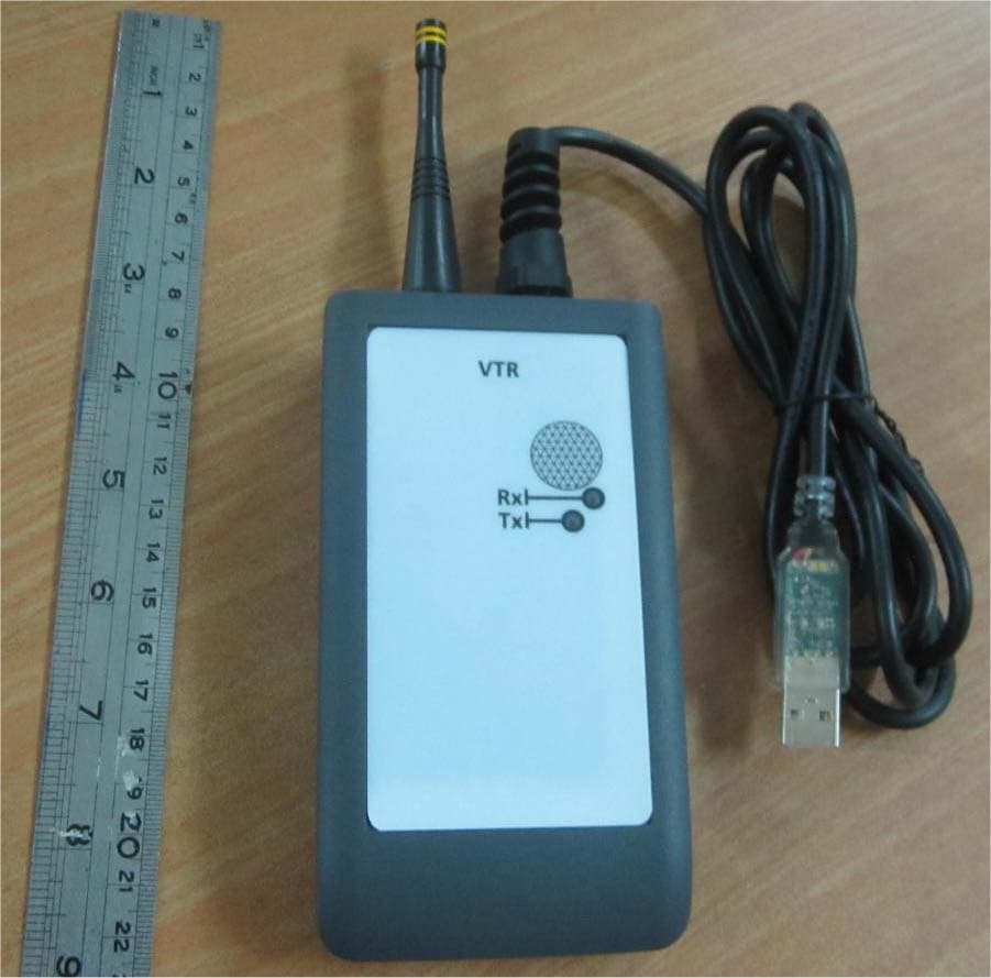
VIDLRVTRMM
Feb 15, 2021LR Platform
Equipment Class
DTS - Digital Transmission System
VIDCMPIT4G
Aug 12, 2020Cellular end point for water meter
Equipment Class
DTS - Digital Transmission System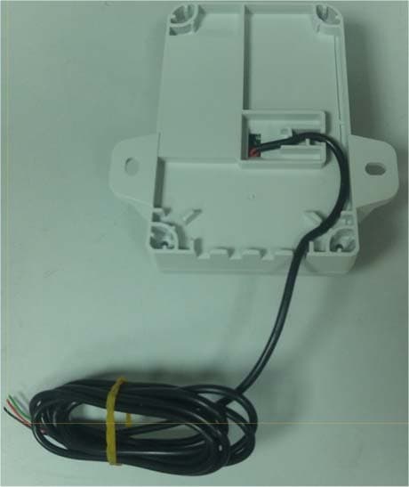
VIDWMNTLG5
Apr 26, 2020Water Meter Wall Mount Unit
Equipment Class
DSS - Part 15 Spread Spectrum Transmitter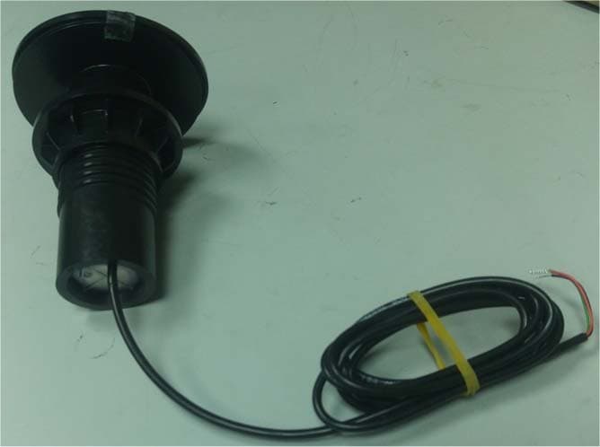
VIDPMNTLG5
Apr 26, 2020Water Meter Pit Unit
Equipment Class
DXT - Part 15 Low Power Transceiver, Rx Verified
VIDICON240V
Sep 03, 2007Electric Meter
Equipment Class
DTS - Digital Transmission System