VIDCMPIT4GCellular end point for water meter
Arad Technologies Ltd.
Click to zoom
Application Details
- Equipment Class
- DTS - Digital Transmission System
- Date of Grant
- Aug 12, 2020
- Application Purpose
- Original Equipment
- Date of Application
- Aug 12, 2020
- Equipment Note
- Cellular end point for water meter
- Frequency Range
- 2402.00000000 - 2480.00000000
- Company
- Arad Technologies Ltd.
- Country
- Israel
Documents & Files
Document Text
Text extracted from the exhibit documents filed with the FCC. Open a document above to read the original.
Users Manual
Allegro Cellular CAT-M PIT Module User Guide FCC ID: VIDCMPIT4G Contains FCC ID: N7NHL78 CAUTION This device complies with part 15 of the FCC Rules. The User and the Installer should be aware that changes and modifications to the equipment not expressly approved by Master Meter could void warranty and the user's authority to operate the equipment. Professionally trained personnel should install the equipment. The antenna used for this transmitter must be installed to normally provide minimum separation distance of at least 20 cm from all persons and must not be co-located or operating in conjunction with any other antenna or transmitter. ATTENTION- FCC Statement This equipment has been tested and found to comply with the limits for a Class B digital device, pursuant to Part 15 of the FCC Rules. These limits are designed to provide reasonable protection against harmful interference in a residential installation. This equipment generates uses and can radiate radio frequency energy and, if not installed and used in accordance with the instructions, may cause harmful interference to radio communications. However, there is no guarantee that interference will not occur in a particular installation. If this equipment does cause harmful interference to radio or television reception, which can be determined by turning the equipment off and on, the user is encouraged to try to correct the interference by one or more of the following measures: -- Reorient or relocate the receiving antenna. -- Increase the separation between the equipment and receiver. -- Connect the equipment into an outlet on a circuit different from that to which the receiver is connected. -- Consult the dealer or an experienced radio/TV technician for help. Introduction The Allegro cellular PIT Module is a battery-operated radio module designed for automated water meter reading. The Allegro cellular is capable of reading water consumption data from residential and commercial water meters equipped with an Encoder or Solid-State Register. It uses CAT-M cellular radio for relaying water consumption data to the utility. Figure 1 – Allegro Cellular PIT Module Electrical Characteristics Battery: • Battery type: Lithium-Thionyl Chloride • Nominal voltage: 3.6 V • Capacity: 8500 mAh DC Characteristics: • Operating voltage range: 3.0 V – 3.6 V • Typical Sleep Current: 10 uA Radio Characteristics: • RF/Antenna: o Typical Antenna Gain: 0dBi o LTE Cat-M1, Power Class 3 (Pout = 23dBm) o Typical Sensitivity TIS = -100dBm o Typical TRP = +20dBm o Software based radio allowing support of extra bands for worldwide operation (B2, 4, 12, 13, 26) • SIM Interface: eSIM • Protocol Stack Cat-M1: o 3GPP Rel. 13 o Half-duplex o Channel bandwidth 1.4MHz o LTE carrier bandwidth 1.4 / 3 / 5 / 10 / 15 / 20 MHz o Up to 375kbit/s uplink, 300 kbit/s downlink o Extended Coverage Mode A o PSM (Power Save Mode) o I-DRX (Idle Mode Discontinuous Reception) o C-DRX (Connected Mode Discontinuous Reception) o Idle mode mobility o Connected mode mobility o eDRX (Extended Discontinuous Reception) Functional Description The Allegro cellular PIT Module is battery endpoint for the application of automatic water meter reading. The primary function of the module is to record consumption of a water meter from an Encoder register. The count from the action of the meter advances the register and passed serially to the radio. Several operational modes are available based on production configuration, standard mode transmit daily 24-hourly meter reads. Figure 2 – Operation setup illustration Installation 1. Remove PIT lid, Figure 3. Figure 3 2. Pass the cable through the Lid hole and Install the PIT Module into the Pit-Set Lid, Figure 4. Figure 4 3. Fasten the PIT Module to the Pit-Set Lid using the fixing nut provided, Figure 5. Figure 5 4. Connect PIT Module cable to water meter inside the Pit-Set, make sure both arrows located in front of each other and tight together, Figure 6. Figure 6 Pay attention! PIT Module may come with variety of cables, plugs, in case of bare wire connect the wires according to Meter manufacturer guidance 5. Place magnet on PIT Module top as illustrated in Figure 7 for 20 seconds than remove the magnet. Figure 7 6. On PIT Module bottom LED will indicate (Figure 8) process as described below. 7. When magnet is sensed LED blinks 3 times. Figure 8 8. Then when magnet was removed (after 20 seconds) LED will blink several times until it finds network and connected. 9. After PIT Module was magnet activated, it will automatically be ready to transmit based on production schedule configuration.
Cover Letter(s)
< A rad Technologies Ltd. > O ffice of Engineering Technology Federal C ommunications Commission 7435 Oakland Mills Road Columbia, MD21046 Subject; Request for Long Term Confidentiality FCC ID: VIDCMPIT4G To Whom It May Concern, Date: 2020-07-08 Pursuant to the provisi。ns。f the Commission ’ s rules Title 4 7 Secti。ns§0.457 and §0.459, we are requesting the Commission to withhold the following attachment(s) as confidential documents from public disclosure indefinitely. These documents contain detailed system and equipment descriptions and are considered as proprieta叩info「mationin operation of the equipment. The public disclosure of these documents · might be harmful to our company and would give competitors an unfair advantage in the market. 国SchematicDiagram 囚BlockDiagram 因OperationalDescription It is our understanding that all measurement test「epo时s,FCC ID label format and co「respondenceduring the certification review process cannot be granted as confidential documents and this information will be available for public review once the grant of equipment authorization is issued. Sincerely , --===- Signature: Name: Avner Libman Title: VP Systems & Pr。,jects
External Photos
Test model number: CAT-M Pit Module
ID Label/Location Info
Model No.: CATM Pit Module Label location
ID Label/Location Info
40 mm 25 mm + 0.8 + 0.5 + 0.3 + 0.1 TOLERANCE 0.5-66-30 30-120120-400 400-1000 0.2 + ISO 2768 NOTES: 1. MATERIAL: a. WHITE POLYESTER. b. TOTAL LABEL THICKNESS: 0.06mm c. ADHESIVE: PERMANENT ACRILYC. d. LAMINATION REQUIRED. e. TEMPERATURE RANGE: -40° TO 150°C. f. CHEMICAL RESISTANCE TO ALCOHOL (ISOPROPYL) 70% AND 99%. g. - UL APROVED LABEL MATERIAL. - UL APPOVED PRINTING. 2. PRINTING: a. THE FONT AND HEIGHT OF THE TEXT ARE SPECIFIED ON THE DRAWING. b. COLOR - BLACK E ID BAR COD 0.22" HIGH, CENTER JUSTIFIED E ID 0.10" HIGH, CENTER JUSTIFIED(*) YY - REPRESENTS THE MANUFACTURING YEAR REV.DESCRIPTIONREFERENCEDATEAPPROVED AFIRST RELEASE21/06/2020 Gilad E 40 mm 25 mm MATERIAL [generic name] : שם SCALE CAT.NO./ REV: NAME APPROVED CHECKED DESIGNED DRAWN DATENAME SHEET OF 30' DR A4 Yanina Milavsky 1 Water-UV resistant CAT-M-Booster FCCID 25x40 Water Measuring Technologies WEIGHT [g] : Yanina Milavsky21/06/2020 UNLESS OTHERWISE SPECIFIED DIMENSIONS ARE IN MILLIMETERS + - 9 50 035 18 /A ( ) 1 Dwg: C:\Arad_Tech_Vault\products\nile booster flute\mechanical\95003518_Water-UV resistant CAT-M-Booster FCCID 25x40Model: Model Rev: ANGULAR STATUS: Arad Measuring Technologies ENGINEERING DEPARTMENT 21/06/2020 1:1 CONTENTS PROPERTY OF ARAD MEASURING TECHNOLOGIES LTD. UNAUTHORIZED USE IS NOT PERMITTED
ID Label/Location Info
May 27, 2019 To Whom It May Concern, RE: Labelling of HL7800 Module The HL7800 module is a Surface Mount Device soldered onto the end product and is not possible for the end-user to replace or remove from the end product. In an effort to reduce the amount of paper/plastic/adhesive label consumption and be a good environmental corporate role model, Sierra Wireless uses laser etching instead of the traditional labels for the module. The laser etching process requires a “no etch” circular area in the centre of the module so that modules can be picked up by vacuum nozzles. The dimension of the module is shown in the drawing below. FCC ID: N7NHL78 IC: 2417C-HL78 Due to the small size of the product and the “no etch” area (marked grey) required for the laser etching process, it is not practical to mark the FCC Identifier and IC certification number in a font size of 4 points or larger. Pursuant to FCC Rule §2.925, the FCC Identifier will be placed in the user manual and on the device packaging. Sierra Wireless hereby seeks agreement from ISED to place the IC certification number in the user manual in accordance with Section 4 of RSS-Gen Issue 5. Sincerely, Denis Chabot Senior Manager, Certification
Internal Photos
Test model number: CAT-M Pit Module
RF Exposure Info
FCC ID: VIDCMPIT4G RF Exposure Evaluation Limits The criteria listed in the following table shall be used to evaluate the environment impact of human exposure to radio frequency (RF) radiation as specified in 1.1307(b) Limits for Maximum Permissible Exposure (MPE) Frequency range (MHz) Electric field strength (V/m) Magnetic field strength (A/m) Power density (mW/cm 2 ) Averaging time (minutes) (A) Limits for Occupational/Controlled Exposures 0.3–3.0 614 1.63 *(100) 6 3.0–30 1842/f 4.89/f *(900/f 2 ) 6 30–300 61.4 0.163 1.0 6 300–1500 f/300 6 1500–100,000 5 6 (B) Limits for General Population/Uncontrolled Exposure 0.3–1.34 614 1.63 *(100) 30 1.34–30 824/f 2.19/f *(180/f 2 ) 30 30–300 27.5 0.073 0.2 30 300–1500 f/1500 30 1500–100,000 1.0 30 f = frequency in MHz Friis transmission formula: Pd = (Pout*G)/(4*pi*r 2 ) Where Pd = power density in mW/cm 2 , Pout = output power to antenna in mW; G = gain of antenna in linear scale, Pi = 3.1416; R = distance between observation point and center of the radiator in cm Pd id the limit of MPE, 1 mW/cm 2 . If we know the maximum gain of the antenna and the total power input to the antenna, through the calculation, we will know the distance r where the MPE limit is reached. Test Procedure Software provided by client enabled the EUT to transmit and receive data at lowest, middle and highest channel individually. Test Result of RF Exposure Evaluation BLE mode Channel Output power to antenna (mW) Power Density at R=20cm (mW/cm 2 ) Limit (mW/cm 2 ) Result Lowest (2402MHz) 3.85 0.0008 1.0 PASS Middle (2440MHz) 3.30 0.0007 1.0 PASS Highest (2480MHz) 2.64 0.0005 1.0 PASS Remark: antenna gain=0dBi So a SAR test is not required
Test Report
Global United Technology Services Co., Ltd. Report No.: GTS202006000257F01 Authorized Signature: Robinson Lo Laboratory Manager This results shown in this test report refer only to the sample(s) tested, this test report cannot be reproduced, except in full, without prior written permission of the company. The report would be invalid without specific stamp of test institute and the signatures of compiler and approver. Page 1 of 36 Test Report (Bluetooth) Applicant: Arad Technologies Ltd. Address of Applicant: 4 Hamada street 537, Yokneam Elit 2069206, Israel Manufacturer/Factory: Arad Technologies Ltd. Address of Manufacturer/Factory: 4 Hamada street 537, Yokneam Elit 2069206, Israel Equipment Under Test (EUT) Product Name: Cellular end point for water meter Model No.: CATM PIT Module Trade Mark: Allegro Cellular FCC ID: VIDCMPIT4G Applicable standards: FCC CFR Title 47 Part 15 Subpart C Section 15.247 Date of sample receipt: June 23, 2020 Date of Test: June 24, 2020-July 08, 2020 Date of report issued: July 08, 2020 Test Result : PASS * * In the configuration tested, the EUT complied with the standards specified above. Report No.: GTS202006000257F01 Page 2 of 36 2 Version Version No. Date Description 00 July 08, 2020 Original Prepared By: Date: July 08, 2020 Project Engineer Check By: Date: July 08, 2020 Reviewer Report No.: GTS202006000257F01 Page 3 of 36 3 Contents Page 1 COVER PAGE ........................................................................................................................................... 1 2 VERSION .................................................................................................................................................. 2 3 CONTENTS .............................................................................................................................................. 3 4 TEST SUMMARY ..................................................................................................................................... 4 5 GENERAL INFORMATION ...................................................................................................................... 5 5.1 GENERAL DESCRIPTION OF EUT ......................................................................................................... 5 5.2 TEST MODE ........................................................................................................................................ 7 5.3 DESCRIPTION OF SUPPORT UNITS ....................................................................................................... 7 5.4 DEVIATION FROM STANDARDS ............................................................................................................. 7 5.5 ABNORMALITIES FROM STANDARD CONDITIONS ................................................................................... 7 5.6 TEST FACILITY .................................................................................................................................... 7 5.7 TEST LOCATION ................................................................................................................................. 7 5.8 ADDITIONAL INSTRUCTIONS ................................................................................................................. 7 6 TEST INSTRUMENTS LIST ..................................................................................................................... 8 7 TEST RESULTS AND MEASUREMENT DATA .................................................................................... 10 7.1 ANTENNA REQUIREMENT ................................................................................................................... 10 7.2 CONDUCTED OUTPUT POWER ........................................................................................................... 11 7.3 CHANNEL BANDWIDTH ...................................................................................................................... 13 7.4 POWER SPECTRAL DENSITY ............................................................................................................. 15 7.5 BAND EDGES .................................................................................................................................... 17 7.5.1 Conducted Emission Method ..................................................................................................... 17 7.5.2 Radiated Emission Method ........................................................................................................ 18 7.6 SPURIOUS EMISSION ......................................................................................................................... 23 7.6.1 Conducted Emission Method ..................................................................................................... 23 7.6.2 Radiated Emission Method ........................................................................................................ 25 8 TEST SETUP PHOTO ............................................................................................................................ 36 9 EUT CONSTRUCTIONAL DETAILS ..................................................................................................... 36 Report No.: GTS202006000257F01 Page 4 of 36 4 Test Summary Test Item Section in CFR 47 Result Antenna requirement 15.203/15.247 (c) Pass AC Power Line Conducted Emission 15.207 N/A Conducted Output Power 15.247 (b)(3) Pass Channel Bandwidth 15.247 (a)(2) Pass Power Spectral Density 15.247 (e) Pass Band Edge 15.247(d) Pass Spurious Emission 15.205/15.209 Pass Remarks: 1. Pass: The EUT complies with the essential requirements in the standard. 2. Test according to ANSI C63.10:2013 Measurement Uncertainty Test Item Frequency Range Measurement Uncertainty Notes Radiated Emission 30MHz-200MHz 3.8039dB (1) Radiated Emission 200MHz-1GHz 3.9679dB (1) Radiated Emission 1GHz-18GHz 4.29dB (1) Radiated Emission 18GHz-40GHz 3.30dB (1…
Text truncated - open the document above for the full version.
Test Setup Photos
Test model number: CAT-M Pit Module Radiated Emission
Contact Information
Applicant
Vily Negreanu(EM&RF Team Leader)
Technical Contact
Test Firm
Global United Technology Services Co. Ltd.Robinson Lo
Technical Specifications
| # | Rule Parts | Frequency Range | Power Output |
|---|---|---|---|
| 1 | 15C | 2.40 GHz - 2.48 GHz | 3.85 mW |
Other Applications from Arad Technologies Ltd.
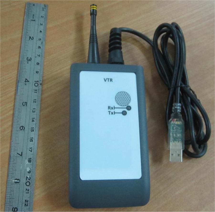
VIDLRVTRMM
Feb 15, 2021LR Platform
Equipment Class
DTS - Digital Transmission System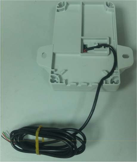
VIDWMNTLG5
Apr 26, 2020Water Meter Wall Mount Unit
Equipment Class
DSS - Part 15 Spread Spectrum Transmitter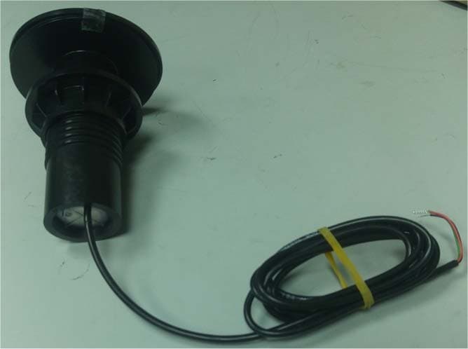
VIDPMNTLG5
Apr 26, 2020Water Meter Pit Unit
Equipment Class
DXT - Part 15 Low Power Transceiver, Rx Verified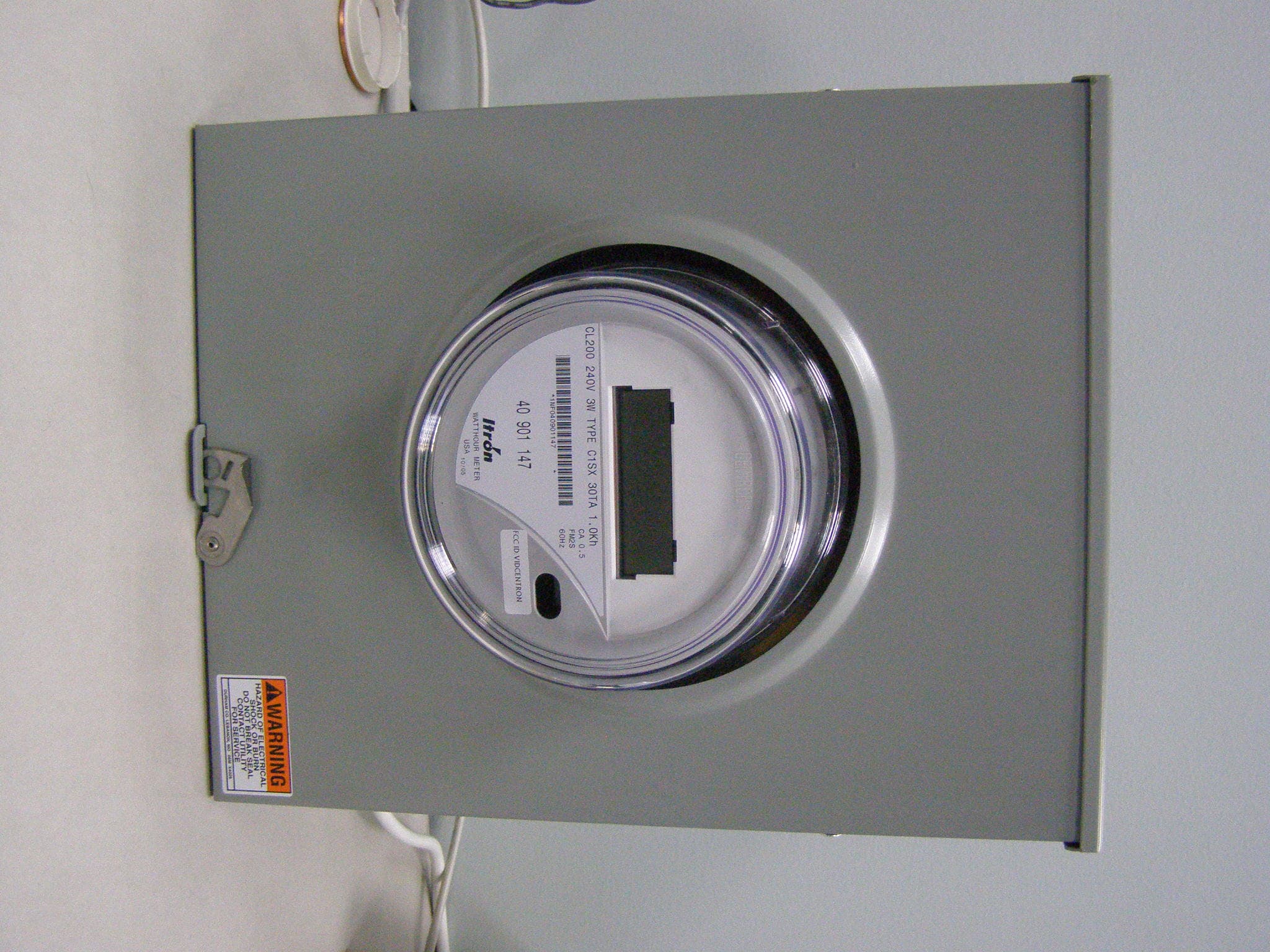
VIDCENTRON
Sep 26, 2007Electric Meter with Transceiver
Equipment Class
DTS - Digital Transmission System
VIDICON240V
Sep 03, 2007Electric Meter
Equipment Class
DTS - Digital Transmission System