VIPFGECMB235Car FM/AM/CD/MP3 Tuner Player with Bluetooth
HUIZHOU FORYOU GENERAL ELECTRONICS CO.,LTD.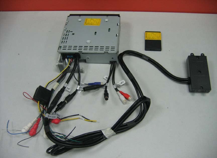
Click to zoom
Application Details
- Equipment Class
- DSS - Part 15 Spread Spectrum Transmitter
- Date of Grant
- Sep 17, 2007
- Application Purpose
- Original Equipment
- Date of Application
- Sep 16, 2007
- Equipment Note
- Car FM/AM/CD/MP3 Tuner Player with Bluetooth
- Frequency Range
- 2402.00000000 - 2480.00000000
- Country
- China
Documents & Files
Document Text
Text extracted from the exhibit documents filed with the FCC. Open a document above to read the original.
Users Manual
i MP6612i TABLE OF CONTENTS Introduction ..............................................................................................1 Installation ................................................................................................2 Wiring .......................................................................................................5 Front Panel Release ................................................................................6 Operation .................................................................................................7 Tuner Operation .....................................................................................11 CD Player Operation ..............................................................................13 MP3/WMA Operation .............................................................................14 Satellite Radio Operation .......................................................................17 iPod Operation .......................................................................................19 Bluetooth Operation ...............................................................................20 Remote Control ......................................................................................24 Care and Maintenance ...........................................................................25 Troubleshooting .....................................................................................26 Specifications .........................................................................................27 Changes or modifications not expressly approved by the party responsible for compliance could void the user's authority to operate the equipment. ii MP6612i MP6612i 1 INTRODUCTION Congratulations on your purchase of the Jensen MP6612i Mobile Receiver. It’s a good idea to read all of the instructions before beginning the installation. We recommend having your Jensen MP6612i installed by a reputable installation shop. Features CD / MP3 / WMA •ID3 Tag Compatible •Last Position Memory •Directory Search (MP3 / WMA Only) •MP3/WMA search by Track, File and Character •Audible Forward / Reverse Track Search •Random, Repeat and Intro •Play, Pause, Stop, Next Track and Previous Track •ESP Buffer (Electronic Shock Protection) AM-FM •RDS-Radio Data System •USA / Europe Frequency Spacing •30 Station Presets (18 FM / 12 AM) •Auto Stereo / Mono •Local / Distance •Auto Store / Preview Scan Sat Radio Ready •Compatible with XM and Sirius Tuners (Sold Separately) •Requires XMDJEN100 or JXMC Cables (Sold Separately) •Satellite Channel Name, Category, Artist, or Song Title can be displayed iPod •JLinkDirect - High Speed Direct Connect Interface To Access iPod Playlists, Artists, Albums, Songs. •Intuitive Interface for Easy iPod Navigation •Power Management Charges iPod While Connected •Requires jLinkCable (Sold Separately) MediaLink 2 •Under Dash Interface Allows Portable Media Devices to be Connected •MediaLink 2 Includes the Following connectivity: •jLinkDirect 8-pin DIN for iPod •USB - Supports Hard Drives and Flash Memory Drives •SD Card - Playback of MP3 and WMA files •3.5mm Audio Only Input Chassis •Detachable Faceplate •1.0 DIN (Import / ISO-DIN Mountable) •Full Dot Matrix LCD Display General •Infrared Remote Control •Programmable Volume Control •MediaPlex AudioCore offers Adjustable Bass, Midrange and Treble Center Frequencies as well as Bass and Midrange Q Adjustments •Five Preset EQ Curves •Loudness •Rotary Encoder Audio Control •Beep Tone Confirmation (On-OFF Option) •Variable Subwoofer Line Output w/ Multiple X-over Frequency Settings •Front and Rear Line Output •200-Ohm Preamp Line Outputs •2VRMS Line Outputs Optional Accessories •jLinkCable - iPod interface Cable MP6612i 2 INSTALLATION This unit is designed for installation in cars, trucks and vans with an existing radio opening. In many cases, a special installation kit will be required to mount the radio to the dashboard. These kits are available at electronics supply stores and car stereo specialty shops. Always check the kit application before purchasing to make sure the kit works with your vehicle. If you have trouble locating a kit or need installation assistance, contact Technical Support at 1-800-323-4815 from 8:30am to 7:00pm EST Monday through Friday and from 9:00am to 5:00pm EST on Saturday. Tools and Supplies The following tools and supplies are needed to install the radio: •Torx type, flathead and Philips screwdrivers •Wire cutters and strippers •Tools to remove existing radio (screwdriver, socket wrench set or other tools) •Electrical tape •Crimping tool •Volt meter/test light •Crimp connections •18 gauge wire for power connections •16-18 gauge speaker wire Preparation 1.Disconnect Battery Before you begin, always disconnect the battery negative terminal. NOTE: If the MP6612i is to be installed in a car equipped with an on- board drive or navigation computer, do not disconnect the battery cable. If the cable is disconnected, the computer memory may be lost. Under these conditions, use extra caution during installation to avoid causing a short circuit. 2. Remove Transport Screws 3.Remove Radio from Sleeve Lift latches on both sides of sleeve to remove half-sleeve from radio. Mounting Sleeve Installation 1. Slide the mounting sleeve off the chassis. If it is locked into position, use the removal tools (supplied) to disengage it. 2. Check the dashboard opening size by sliding the mounting sleeve into it. If the opening is too small, carefully cut or file as necessary until the sleeve easily slides into the opening. Do not force the sleeve into the opening or cause it to bend or bow. Check for sufficient space behind the dashboard for the radio chassis. 3. Locate the series of bend tabs along the top, bottom, and sides of the mounting sleeve. With the sleeve fully inserted into the dashboard opening, bend as many of the tabs outward as necessary to firmly secure the sleev…
Text truncated - open the document above for the full version.
Cover Letter(s)
We have added the photos of the daughter board to internal photos. Please refer to page 2 of the label location. The revised label location has been uploaded to website. The Block diagram and schematics of the TX have been uploaded to website. Changed the equipment type “D××” to “DSS” in the Form-731. . We have deleted the information “Test the EUT as a product which has frequency hopping system. The total hopping channels are 74 channels (1 to 74 channels), the fundamental frequencies are from 2.410GHz to 2.470GHz.” from the test report. Please refer to P7 of the test report for details. List the Rated RF power output of the device in the 731 Form. Corrected test values in the power table. Please refer to P8 of the test report for details. Changed “74 channel numbers” to “79 channels”. Please refer to P38 of the test report for details.
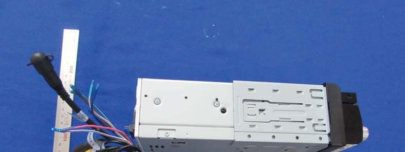
Internal Photos
FCC ID: VIPFGECMB235 FCC ID: VIPFGECMB235 FCC ID: VIPFGECMB235 FCC ID: VIPFGECMB235 FCC ID: VIPFGECMB235 FCC ID: VIPFGECMB235 FCC ID: VIPFGECMB235 FCC ID: VIPFGECMB235 Module: FCC ID: VIPFGECMB235 FCC ID: VIPFGECMB235
Test Report
SGS-CSTC Standards Technical Services Co., Ltd. Report No.: GLEMR070702247RFT FCC ID:VIPFGECMB235 Page: 1 of 49 Authorized Signature: Stephen Guo Manager This report refers to the General Conditions for Inspection and Testing Services, printed overleaf This report details the results of the testing carried out on one sample. The results contained in this test report do not relate to other samples of the same product. The manufacturer should ensure that all products in series production are in conformity with the product sample detailed in this report. This report may only be reproduced and distributed in full. If the product in this report is used in any configuration other than that detailed in the report, the manufacturer must ensure the new system complies with all relevant standards. Any mention of SGS International Electrical Approvals or testing done by SGS International Electrical Approvals in connection with, distribution or use of the product described in this report must be approved by SGS International Electrical Approvals in writing. Member of the SGS Group (Société Générale de Surveillance) No.198 Kezhu Road, Science Town Economic& Technology Development District Guangzhou, China 510663Telephone: Telephone: +86 (0) 20 82155555 Fax: +86 (0) 20 82075059Email: [email protected] FEDERAL COMMUNICATIONS COMMISSION Registration number: 282399 TEST REPORT Application No. : GLEMR070702247RF Applicant: HUIZHOU FORYOU GENERAL ELECTRONICS CO.,LTD FCC ID: VIPFGECMB235 Fundamental Carrier Frequency : 2.402GHz to 2.480GHz Equipment Under Test (EUT): Name: Car CD/MP3 Player with FM/AM Tuner Model No.: CMB235, MP6612i ♣ Standards: FCC PART 15, SUBPART B: 2006 FCC PART 15, SUBPART C: 2006 (Section 15.247) Date of Receipt: 27 June 2007 Date of Test: 27 June to 08 August 2007 Date of Issue: 09 August 2007 Test Result : PASS * * In the configuration tested, the EUT detailed in this report complied with the standards specified above. Please refer to section 2 of this report for further details. SGS-CSTC Standards Technical Services Co., Ltd. Report No.: GLEMR070702247RFT Page: 2 of 49 FCC ID: VIPFGECMB235 2 Test Summary For Bluetooth Function: Test Test Requirement Standard Paragraph Result Maximum Peak Output Power FCC PART 15 :2006Section 15.247(b)(1) PASS Conducted Emission FCC PART 15 :2006 Section 15.107 Section 15.207 N/A Conducted Spurious Emission (30MHz to 25GHz) FCC PART 15 :200615.247(d) PASS Radiated Spurious Emission (30MHz to 25GHz) FCC PART 15 :2006 Section 15.109, Section 15.209 &15.247(d) PASS Band Edges Measurement FCC PART 15 :2006 Section 15.247 (d) &15.205 PASS Hopping Channel Number FCC PART 15 :2006 Section 15.247(a)(1)(iii) PASS Carrier Frequencies Separated FCC PART 15 :2006Section 15.247(a)(1) PASS Dwell Time FCC PART 15 :2006 Section 15.247(a)(1)(iii) PASS Antenna Requirement FCC PART 15 :2006Section 15.247 (c) PASS ♣ Remark: According to the confirmation from the applicant, model CMB235, MP6612i were the same as in the circuit, PCB layout, electrical parts. The difference was the appearance. Therefore only one model need to be tested. SGS-CSTC Standards Technical Services Co., Ltd. Report No.: GLEMR070702247RFT Page: 3 of 49 FCC ID: VIPFGECMB235 3 Contents Page 1 COVER PAGE ...........................................................................................................................................1 2 TEST SUMMARY ....................................................................................................................................... 2 3 CONTENTS ................................................................................................................................................ 3 4 GENERAL INFORMATION ........................................................................................................................ 4 4.1 CLIENT INFORMATION.............................................................................................................................. 4 4.2 GENERAL DESCRIPTION OF E.U.T. .......................................................................................................... 4 4.3 DESCRIPTION OF SUPPORT UNITS........................................................................................................... 4 4.4 STANDARDS APPLICABLE FOR TESTING.................................................................................................... 4 4.5 TEST LOCATION...................................................................................................................................... 4 4.6 OTHER INFORMATION REQUESTED BY THE CUSTOMER............................................................................. 4 4.7 TEST FACILITY........................................................................................................................................ 5 5 EQUIPMENTS USED DURING TEST........................................................................................................ 6 6 TEST RESULTS ......................................................................................................................................... 7 6.1 E.U.T. OPERATION................................................................................................................................. 7 6.2 MAXIMUM PEAK OUTPUT POWER............................................................................................................ 7 6.3 CONDUCTED EMISSION......................................................................................................................... 10 6.4 RADIATED EMISSIONS........................................................................................................................... 10 6.5 CONDUCTED SPURIOUS EMISSIONS....................................................................................................... 21 6.6 RADIATED SPURIOUS EMISSIONS............................................................................…
Text truncated - open the document above for the full version.
Test Setup Photos
Radiated Spurious Emission Test Setup
Contact Information
Applicant
Joey Zhang(Engineer)
Technical Contact
SGS-CSTC Standards Technical Services Ltd.Stephen Guo
[email protected]86 20 82155301
198 Kezhu Road, Scientech Park · Guangzhou · China
Non-Technical Contact
SGS-CSTC Standards Technicla Services Ltd.Cherry Li
[email protected]86 20 82155317
Test Firm
SGS-CSTC Standards Technical Services Co., LtdJerry Chan
Technical Specifications
| # | Rule Parts | Frequency Range | Power Output |
|---|---|---|---|
| 1 | 15C | 2.40 GHz - 2.48 GHz | 800.00 µW |
Other Applications from HUIZHOU FORYOU GENERAL ELECTRONICS CO.,LTD.
VIP-VX7012
Apr 08, 2015Car Multimedia Player
Equipment Class
DSS - Part 15 Spread Spectrum Transmitter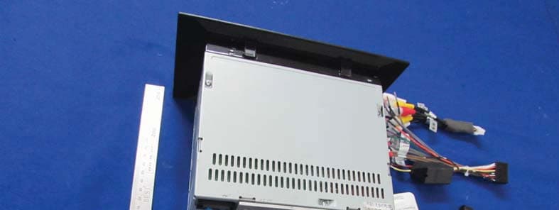
VIP-VX7022
Apr 08, 2015Car Multimedia Player
Equipment Class
DSS - Part 15 Spread Spectrum Transmitter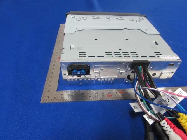
VIP-VX3012
Feb 12, 2015Car Multimedia Player
Equipment Class
DSS - Part 15 Spread Spectrum Transmitter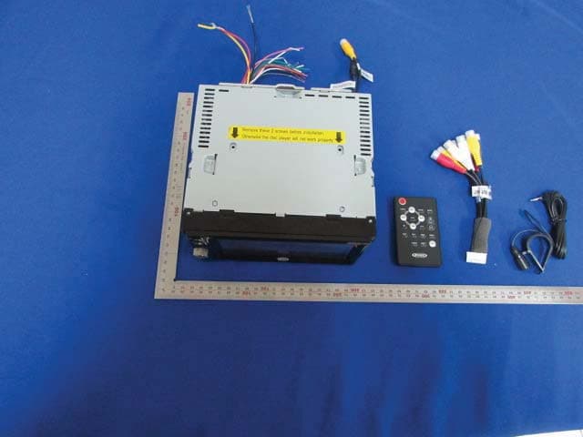
VIP-VX3022
Feb 11, 2015Car Multimedia Player
Equipment Class
DSS - Part 15 Spread Spectrum Transmitter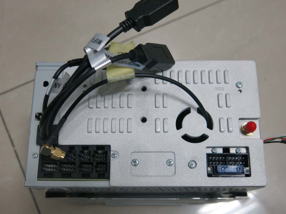
VIP-DVA6
Sep 08, 2014Car Multimedia Receiver
Equipment Class
DSS - Part 15 Spread Spectrum Transmitter