VL6JA85PWireless PIR detector- Component of Alarm system
Jablotron Ltd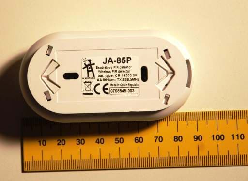
Click to zoom
Application Details
- Equipment Class
- DSC - Part 15 Security/Remote Control Transmitter
- Date of Grant
- Dec 17, 2007
- Application Purpose
- Original Equipment
- Date of Application
- Dec 17, 2007
- Equipment Note
- Wireless PIR detector- Component of Alarm system
- Frequency Range
- 868.50000000 - 868.50000000
- Company
- Jablotron Ltd
- Country
- Czech Republic
Documents & Files
Document Text
Text extracted from the exhibit documents filed with the FCC. Open a document above to read the original.
Users Manual
The JA-80P mini-size wireless motion detector 1 / 1 MHP52700_PTS_FCC The JA-85P mini-size wireless motion detector The JA-85P is a component of Jablotron’s Oasis 80 alarm system. The mini- size motion detector uses a PIR sensor and it is designed for indoor use in buildings or in cars. The battery-powered detector communicates via OASIS radio protocol. open here + lithium battery AA 3V DIP switches - see table AA 3V PCB release s e c u r e d ( C L I C K ) Installation Installation shall only be undertaken by technicians holding a certificate issued by an authorized distributor. The detector can be installed on a wall or on a ceiling. In a car it can be installed high on the interior vertical surface between the front and rear doors. Within the detection range of the PIR sensor avoid the presence of objects rapidly changing in temperature, such as electrical heaters, gas appliances etc. Moving objects with a temperature close to that of humans such as curtains moving above a radiator, and pets should also be avoided. Detectors should not be near fast-moving air e.g. near ventilation fans or open windows or doors. There should also be no obstacles blocking the detector’s “view” of the protected area. Keep the detector away from metal objects which could interfere with radio communication. Warning: The most frequent cause of false alarms is bad detector- positioning. Do not set (arm) this detector if there are any people or pets moving within the protected area. 1. Release the detector installation bracket (by turning it clockwise). 2. Attach the bracket to a desired place and reinstall the detector onto the bracket. 3. Open the detector cover by pressing the tab. 4. Remove the internal PIR module held by an internal tab. 5. Set the detector DIP switches (see the “DIP switches” section below). 6. Return the PIR module into the plastic cover. 7. Leave the battery disconnected and the detector open and then follow the receiver (or control panel or car alarm) manual. The detector enrolls by connecting up its battery while the receiver is in enrollment mode. 8. After detector enrollment, close its cover, wait until its indicator turns off and then test its functionality. To enroll a detector after having already connected a battery, first disconnect the battery, wait 30 seconds and reconnect it. DIP switches # OFF ON 1 Increased immunity with a slower reaction (car use) Normal immunity to false alarms (indoor use) 2* Delayed natural reaction Instant natural reaction 3** Radio supervision off Radio supervision on 4*** 5 minute sleep time 1 minute sleep time * This DIP switch has an effect if the detector is used with a CA car alarm or with an Oasis control panel which has a natural reaction assigned to the JA-85P’s address. It also has no effect when used with a UC-8x or AC-8x receiver. ** Radio communication supervision should be switched off if a detector installed in a car is enrolled to an Oasis control panel in a house (to avoid lost detector indication when the car drives away). *** To save battery energy, the detector switches to battery-save mode 15 minutes after the cover is closed. During battery-save mode the PIR sensor still always watches out for movement. The first movement detected is then transmitted instantly, and for the next 5 minutes or 1 minute the PIR sensor ignores any further movement. After this period, the PIR sensor then returns to watching out for movement until re-triggered. Testing the detector 15 minutes after closing the detector cover, the LED shows detector triggering. The strength and quality of detector signals can be measured by an Oasis control panel in Service mode. If the detector is enrolled to a car alarm and the ignition key is turned off then detector triggering is indicated by a short flash of the LED. Battery replacement The detector battery is regularly checked. If the battery has expired, then the user or installer is informed. The detector continues to work and each movement in front of the detector is shown by a brief LED flash. The battery should be replaced within two weeks by a qualified technician. After battery replacement the detector needs two minutes to stabilise during which the LED is permanently lit. After battery replacement test the functioning of the detector. An expired battery should not be thrown into the garbage, but disposed of according to local regulations. Detection characteristics The detector can react to movements within a distance of up to 5 meters, see the following diagram. r = 3m r = 5m 4 m 2.60m Car alarm co-operation Several types of Jablotron’s car alarms allow for wireless detector enrollment. A JA-85P detector, if enrolled, should be placed in the upper part of car’s interior – e.g. fixed to the plastic part of the ceiling light, to side posts or to the ceiling upholstery (this does not require the bottom handle to be used). Always take the detection characteristic into consideration when positioning the detector. Keep in mind that the spots behind mechanical obstacles (seats, props) are invisible to the detector. Multiple detectors can be used simultaneously – a detector has no effect to other detectors function. The detector should not be exposed to direct sunlight. When arming a car with a JA-85P enrolled all windows must be closed to prevent false alarm caused by strong hot air blasts or by passing-by persons. However, this rule can be omitted when partial arming is used and the detector belongs to the INT group. DIP switches No. 1 and 3 must be OFF. Technical specifications Voltage Lithium battery type CR14505 (AA 3.0V) Calculated battery lifetime approx. 3 years (sleep time 5 min.) Communication band: 868 MHz, Oasis protocol Communication range: approx. 100m (open area) PIR sensor detection angle/detection range: 360° / 5 m Operational environment according to EN 50131-1 II. internal space Operational temperature range -10 to +55 °C Dimensions 88 x 46 x 27mm EN 50131-1, CLC/TS 50131-2-2, EN 50131-5-3 classi…
Text truncated - open the document above for the full version.
Cover Letter(s)
JABLOTRON s.r.o. TEL:+420-483 559 854 Pod Skalkou 33 FAX:+420-483 559 853 466 01 Jablonec nad Nisou www.jablotron.cz Czech Republic mail to: [email protected] Account: KomerčnÌ banka Jablonec n.N 17409-451/0100 Entrepreneurial permit number: CZ14864959 Spisov· značka: C/141 veden· u rejstřÌkovÈho soudu v ⁄stÌ nad Labem. Intertek Deutschland GmbH Innovapark 20 DE- 87600 Kaufbeuren Attention: Application Examiner Re: Request for confidentiality Applicant: JABLOTRON Ltd. FCC ID: VL6JA85P To whom it may concern, Request is hereby submitted by JABLOTRON to withhold permanently from public review certain portions of the application for equipment certification for the referenced FCC identifiers. This request for confidentiality is made pursuant to 47 CFR 0.457(d) and 0.459 of the FCC Rules. In particular, the following sections of the application are to be kept permanently confidential: • Schematics • Detailed Block diagrams Rationale for request for confidentiality: JABLOTRON has invested considerable time and materials in research and development to produce the referenced product. Disclosure of the permanently confidential portions of this application to competitors would not only give them significant competitive advantages in developing similar products, but would also disclose successful implementation of unpublished, leading edge technology developed by us. Sincerely Milan Holas, dipl. Eng. __________________ ________________ Signature Printed Title: Technical legislation and metrology manager
Cover Letter(s)
JABLOTRON s.r.o. TEL:+420-483 559 854 Pod Skalkou 33 FAX:+420-483 559 853 466 01 Jablonec nad Nisou www.jablotron.cz Czech Republic mail to: [email protected] No: 7DO014 Konto: KomerčnÌ banka Jablonec n.N 17409-451/0100 IČO: 14864959 DIČ: 187-14864959 Spisov· značka: C/141 veden· u rejstřÌkovÈho soudu v ⁄stÌ nad Labem. Intertek Deutschland GmbH Innovapark 20 DE- 87600 Kaufbeuren July 30, 2007 To whom it may concern, Letter of Agency I, an officer of Jablotron company do hereby authorize Intertek Deutschland GmbH to act on our behalf in front of the Federal Communications Commission with respect to all matters relating to certification of equipment under Part 15 of the FCC Rules until further notice. I further certify that no party (as defined in ß1.2002(b) of CFR 47, 2004) to this application, including myself, is subject to a denial of federal benefits, that includes FCC benefits, pursuant to Section 5301 of the Anti-Drug Abuse Act of 1988, 21 U.S.C., 862. Regards, By: Milan Holas, dipl. Eng. __________________ ________________ Signature Printed Title: Technical legislation and metrology manager ____________________
External Photos
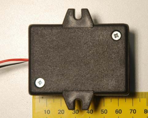
External Photos External view from sensor side External view from rear side
ID Label/Location Info
The position of the FCC label : rear side of the device above the company label as shown on the drawing above.
Internal Photos
Internal Photos Internal view after cover removal Internal view from sensor side
Operational Description
Operational description The JA-85P is a component of Jablotron’s Oasis 80 alarm system. The mini- size motion detector uses a PIR sensor and it is designed for indoor use in buildings or in cars. The battery-powered detector communicates via OASIS radio protocol with control panel. The transmitter is activated by infra-red signal caused by human body movement. Under normal conditions the transmitter sends periodically every 540 s the data pulse (system integrity test) of length 30 ms. Antenna is internal. Operational frequency : 868,5 MHz Battery : : Lithium battery type CR14505 (AA 3.0V)
Test Report
Jablotron s.r.o. / JA-85P 2-20 07KFE007857-E-FCC-01 / 07-09-29 R_FCC 06-04 Table of Contents 1. General description.............................................................................................. 4 1.1. Product description ............................................................................................ 4 1.2. Related submittal(s) Grants................................................................................ 4 1.3. Test Methodology............................................................................................... 4 1.4. Test Facility ........................................................................................................ 5 1.5. List of exhibits .................................................................................................... 5 2. Measurements And Test Specifications............................................................. 6 3. Description Of EUT .............................................................................................. 7 3.1. Configuration / Operating Conditions ................................................................. 7 3.2. Major Subassemblies Or Internal Peripherals .................................................... 7 3.3. Peripheral Devices Used For Testing................................................................. 7 3.4. Supply- And Interconnecting Cables .................................................................. 7 4. Test Results - Overview ....................................................................................... 8 5. Measurement results detailed ............................................................................ 9 5.1. Duty cycle and Averaging factor......................................................................... 9 5.2. Bandwidth ........................................................................................................ 11 5.3. Radiated Emission 30 MHz – 10 GHz.............................................................. 12 5.3.1. Field strength calculation..................................................................................................... 12 5.3.2. Normative references .......................................................................................................... 13 5.3.3. Emission Test results .......................................................................................................... 14 6. Test setup Photo documentation...................................................................... 18 7. EUT Photo documentation ................................................................................ 20 8. Technical specification ...................................................................................... 20 Jablotron s.r.o. / JA-85P 3-20 07KFE007857-E-FCC-01 / 07-09-29 R_FCC 06-04 8.1. Block Diagram Of The EUT..............................................................................20 8.2. Circuit Diagram Of The Layout.........................................................................20 8.3. Instruction manual............................................................................................ 20 8.4. Product Labelling ............................................................................................. 20 Jablotron s.r.o. / JA-85P 4-20 07KFE007857-E-FCC-01 / 07-09-29 R_FCC 06-04 4 1. General description 1.1. Product description The JA-85P is a component of Jablotron’s Oasis 80 alarm system. The mini-size motion detector uses a PIR sensor and it is designed for indoor use in buildings or in cars. The battery-powered detector communicates via OASIS radio protocol. It is activated to alarm state when the passive infra-red sensor detects and evaluates human movement. The wireless transmitter (connection to control unit) has operating frequency f = 868.5 MHz. The device is battery operated. The power source delivered by producer and used for testing was a new LiMh accumulator, type CR 14505; U = 3V. Antenna type : Internal, Integral Under normal operating conditions (no alarm state) the device transmits 30 ms data pulse to control unit once in 540 s (9 minutes). 1.2. Related submittal(s) Grants This is application for certification of the transmitter. No related devices are present. 1.3. Test Methodology The test setup and test was done according to: ANSI C63.4: 2003 American National Standard for Methods of Measurement of Radio-Noise Emissions from Low-Voltage Electrical and Electronic Equipment in the Range of 9 kHz to 40 GHz. The test setup and test was done according to: CISPR 22: 1998 + Corrigendum: 2003 + A1: 2000 + A2: 2003 and ANSI C63.4: 2003 Compliance with CISPR 22 is being used to demonstrate conformity with FCC DoC requirements. This conforms with FCC Part 15.109(g). The test results detailed in this report apply only to the JA-85P with the test setup described. Any modification such as a change, addition to or inclusion of another device into this product will require an additional evaluation. The support equipment listed as part of the emission tests is required to properly exercise and test the device under test. Jablotron s.r.o. / JA-85P 5-20 07KFE007857-E-FCC-01 / 07-09-29 R_FCC 06-04 5 1.4. Test Facility The test site was semi-anechoic chamber Intertek Germany (PM KF 1150). Measurement distance EUT – Antenna was d = 3 m. 1.5. List of exhibits Following exhibits are delivered as separate pdf files. The name of file corresponds with description of exhibit with extension .pdf EXHIBIT 1 Test setup photo documentation EXHIBIT 2 External Photos EXHIBIT 3 Internal Photos EXHIBIT 4 Operational description EXHIBIT 5 Block diagram EXHIBIT 6 Circuit diagram EXHIBIT 7 Instruction manual EXHIBIT 8 Product label EXHIBIT 9 Confidentiality request Jablotron s.r.o. / JA-85P 6-20 07KFE007857-E-FCC-01 / 07-09-29 R_FCC 06-04 6 2. Measurements And Test Specifications Emission - Requirements according to FCC, Part 15, Class A, verification …
Text truncated - open the document above for the full version.
Test Setup Photos
Test setup Photo documentation Fig. 1 Front view Fig. 2 Rear view
Contact Information
Applicant
Pavel Cerny
Technical Contact
Jablotron LtdMilan Holas
[email protected]+420483559940
Pod Skalkou 33 · Jablonec nad Nisou · Czech Republic
Non-Technical Contact
Jablotron Ltd.Pavel Cerny
[email protected]+420 483 559 966
Test Firm
Intertek ETL SEMKOThomas Wiegner
Technical Specifications
| # | Rule Parts | Frequency Range | Power Output |
|---|---|---|---|
| 1 | 15.231 | 868.5 MHz - 868.5 MHz | - |
Other Applications from Jablotron Ltd
VL6RC85
Mar 04, 2008Transmitter - component of alarm system
Equipment Class
DSC - Part 15 Security/Remote Control Transmitter
VL6JA82R
Feb 04, 2008Radio module for control unit JA-82K
Equipment Class
DSC - Part 15 Security/Remote Control Transmitter
VL6JA80M
Jan 24, 2008Wireless magnetic door detector
Equipment Class
DSC - Part 15 Security/Remote Control Transmitter
VL6JA80PB
Jan 22, 2008Wireless PIR motion / glass-break detector
Equipment Class
DSC - Part 15 Security/Remote Control Transmitter
VL6JA80E
Jan 20, 2008Hard wired keypad with RFID card reader
Equipment Class
DCD - Part 15 Low Power Transmitter Below 1705 kHz