VLJ-LUX64BUVideo baby monitor
Binatone Electronics International Ltd.
Click to zoom
Application Details
- Equipment Class
- DSS - Part 15 Spread Spectrum Transmitter
- Date of Grant
- Jan 15, 2020
- Application Purpose
- Original Equipment
- Date of Application
- Jan 15, 2020
- Equipment Note
- Video baby monitor
- Frequency Range
- 2402.00000000 - 2477.00000000
- Country
- China
Documents & Files
Document Text
Text extracted from the exhibit documents filed with the FCC. Open a document above to read the original.
Users Manual
User’s Guide 5" HD Wi-Fi ® Video Baby Monitor Models: LUX65CONNECT, LUX65CONNECT-2, LUX65CONNECT-3, LUX65CONNECT-4 The features described in this User’s Guide are subject to modifications without prior notice. CONNECTVIEW65 PLUS, CONNECTVIEW65-2 PLUS, CONNECTVIEW65-3 PLUS, CONNECTVIEW65-4 PLUS Welcome... to your new Motorola Digital Video Baby Monitor! Thank you for purchasing the Digital Video Baby Monitor. Now you can see and hear your baby sleeping in another room or you can monitor your older children in their play room. Please retain your original dated sales receipt for your records. For warranty service of your Motorola product, you will need to provide a copy of your dated sales receipt to confirm warranty status. Registration is not required for warranty coverage. For product-related questions, please call: This User's Guide provides you with all the information you need to get the most from your product. Before you use the Digital Video Baby Monitor, we recommend that you fully charge the battery that is pre-installed in the Parent Unit, so that it continues to work if you disconnect it from the power supply. Please read the Safety Instructions on pages 8 - 10 before you install the Units. Got everything? • 1 x Parent Unit • 1 x Baby Unit (Camera) •1 x Power adapter for Parent Unit • 1 x Power adapter for Baby Unit In multi-camera packs, you will find one or more additional Camera Units with power adapters. +44 (0) 844 557 0890 (UK only)* *Calls cost 7p per minute plus your telephone company's access charge +44 (0) 8187 62092 (ROI) On the Web: www.motorolastore.com Overview of the Parent Unit 1. Display (LCD screen) 2. Charging LED RED when mains power connected. 3. Parent Unit ON/OFF LED (Green) 4. Audio Level LEDs (Green, Green, Amber, Red) 5. Volume Down Press to decrease Volume level. 6. Volume Up Press to increase Volume level. 7. Microphone 8. Display ON/Microphone 9. MENU button Press to open / close the Menu options. 10. Navigation button Move Up/Down/Right/Left menu options. 11. OK button 12. TALK button Press and hold to speak to your baby. 13. Power button Press and Hold to turn the Parent Unit ON/OFF. VIDEO ON/OFF button Press to turn the LCD screen ON/OFF (Note: audio is maintained.) 14. RESET button (recessed - use small pin) 15. Power Socket 16. Stand 17. Speaker 1234567 14 15 8 9 11 10 12 13 16 17 Parent Unit menu icons Signal Level (5 Levels) Night Vision Mode (Video also changes to Black/White) T Ta l k M o d e Volume Level Control (5 Levels) Zoom Level Control (1X, 2X) Brightness Level Control (8 Levels) Lullaby Control (5 Sound Selections) Alarm Setting (6h, 4h, 2h, OFF) Temperature scale select ( o C / o F) Readings display in BLUE, but turn RED > 29ºC / 84ºF, or < 14ºC / 57ºF Displays HH o C / o F if >36 o C / 97 o F. Displays LL o C / o F if < 1 o C / 34 o F. Camera Control (scan, view, add, delete) Set Screen Off Timer (Off , 5 min, 30 min, 60 min) Indicates the screen off timer is set Volume Level Control (8 Levels) No Baby Unit detected View multiple cameras on screen. Available when you have more than 1 Baby Unit (Camera). V Overview of Your Baby Unit Important guidelines for installing your Digital Video Baby Monitor • To use your Baby Unit and Parent Unit together, you must be able to establish a radio link between them, and the range will be affected by environmental conditions. • Any large metal object, like a refrigerator, a mirror, a filing cabinet, a metallic door or reinforced concrete, between the Baby Unit and Parent Unit may block the radio signal. • The signal strength may also be reduced by other solid structures, like walls, or by radio or electrical equipment, such as TVs, computers, cordless or mobile phones, fluorescent lights or dimmer switches. • Other 2.4GHz products, such as wireless networks (Wi-Fi ® routers), Bluetooth™ systems, microwave ovens or other Baby Monitors, may cause interference with this product, so keep the Baby Monitor at least 5ft (1.5m) away from these types of product, or switch them off if they appear to be causing interference. • If the signal is weak, try moving the Parent and/or the Baby Unit to different positions in the rooms. 1. Photo Sensor (Night Vision Mode) 2. Camera Lens 3. Infrared LEDs (x 8, for night vision) 4. High Sense Microphone 5. Magnet mount 6. Power/Link indicatior 7. PAIR button 8. Speaker 9. Power Socket 10 Temperature Sensor 1 2 4 5 3 10 9 8 7 6 6Table of contents Table of contents 1.Safety Instructions ..................................................................................... 8 2.Getting Started........................................................................................ 11 2.1Baby Unit Power Supply............................................................................ 11 2.2Parent Unit Power Supply ......................................................................... 12 2.3Registration (Pairing) ................................................................................ 13 3.Using the Baby Monitor ........................................................................... 14 3.1Setting Up .................................................................................................. 14 3.2Night Vision Mode .................................................................................... 14 3.3Talk Mode.................................................................................................. 14 3.4Video ON/OFF ......................................................................................... 14 3.5Temperature Display (HH °C / °F or LL °C / °F)...................................... 14 4.Parent Unit Menu Options ...................................................................... 15 4.1Volume ...................................................................................................... 15 4.2Brightness .................................................................................................. 15 4.3Lullaby .......…
Text truncated - open the document above for the full version.
Users Manual
User’s Guide 4.3" HD Wi-Fi ® Video Baby Monitor Models: LUX64CONNECT, LUX64CONNECT-2, LUX64CONNECT-3, LUX64CONNECT-4 The features described in this User’s Guide are subject to modifications without prior notice. Welcome... to your new Motorola Digital Video Baby Monitor! Thank you for purchasing the Digital Video Baby Monitor. Now you can see and hear your baby sleeping in another room or you can monitor your older children in their play room. Please retain your original dated sales receipt for your records. For warranty service of your Motorola product, you will need to provide a copy of your dated sales receipt to confirm warranty status. Registration is not required for warranty coverage. For product-related questions, please call: This User's Guide provides you with all the information you need to get the most from your product. Before you use the Digital Video Baby Monitor, we recommend that you fully charge the battery that is pre-installed in the Parent Unit, so that it continues to work if you disconnect it from the power supply. Please read the Safety Instructions on pages 8 - 10 before you install the Units. Got everything? • 1 x Parent Unit • 1 x Baby Unit (Camera) • 1 x Power adapter for Parent Unit • 1 x Power adapter for Baby Unit In multi-camera packs, you will find one or more additional Camera Units with power adapters. US and Canada 1-888-331-3383 E-mail: [email protected] Overview of the Parent Unit 1. Display (LCD screen) 2. Charging LED RED when mains power connected. 3. Parent Unit ON/OFF LED (Green) 4. Audio Level LEDs (Green, Green, Amber, Red) 5. Volume Down Press to decrease Volume level. 6. Volume Up Press to increase Volume level. 7. Microphone 8. Display ON/Microphone 9. MENU button Press to open / close the Menu options. 10. Navigation button Move Up/Down/Right/Left menu options. 11. OK button 12. TALK button Press and hold to speak to your baby. 13. Power button Press and Hold to turn the Parent Unit ON/OFF. VIDEO ON/OFF button Press to turn the LCD screen ON/OFF (Note: audio is maintained.) 14. RESET button (recessed - use small pin) 15. Power Socket 16. Stand 17. Speaker 1234567 14 15 8 9 11 10 12 13 16 17 Parent Unit menu icons Signal Level (5 Levels) Night Vision Mode (Video also changes to Black/White) T Ta l k M o d e Volume Level Control (5 Levels) Zoom Level Control (1X, 2X) Brightness Level Control (8 Levels) Lullaby Control (5 Sound Selections) Alarm Setting (6h, 4h, 2h, OFF) Temperature scale select ( o C / o F) Readings display in BLUE, but turn RED > 29ºC / 84ºF, or < 14ºC / 57ºF Displays HH o C / o F if >36 o C / 97 o F. Displays LL o C / o F if < 1 o C / 34 o F. Camera Control (scan, view, add, delete) Set Screen Off Timer (Off , 5 min, 30 min, 60 min) Indicates the screen off timer is set Volume Level Control (8 Levels) No Baby Unit detected View multiple cameras on screen. Available when you have more than 1 Baby Unit (Camera). V Overview of Your Baby Unit Important guidelines for installing your Digital Video Baby Monitor • To use your Baby Unit and Parent Unit together, you must be able to establish a radio link between them, and the range will be affected by environmental conditions. • Any large metal object, like a refrigerator, a mirror, a filing cabinet, a metallic door or reinforced concrete, between the Baby Unit and Parent Unit may block the radio signal. • The signal strength may also be reduced by other solid structures, like walls, or by radio or electrical equipment, such as TVs, computers, cordless or mobile phones, fluorescent lights or dimmer switches. • Other 2.4GHz products, such as wireless networks (Wi-Fi ® routers), Bluetooth™ systems, microwave ovens or other Baby Monitors, may cause interference with this product, so keep the Baby Monitor at least 5ft (1.5m) away from these types of product, or switch them off if they appear to be causing interference. • If the signal is weak, try moving the Parent and/or the Baby Unit to different positions in the rooms. 1. Photo Sensor (Night Vision Mode) 2. Camera Lens 3. Infrared LEDs (x 8, for night vision) 4. High Sense Microphone 5. Magnet mount 6. Power/Link indicatior 7. PAIR button 8. Speaker 9. Power Socket 10 Temperature Sensor 1 2 4 5 3 10 9 8 7 6 6Table of contents Table of contents 1.Safety Instructions ..................................................................................... 8 2.Getting Started........................................................................................ 11 2.1Baby Unit Power Supply............................................................................ 11 2.2Parent Unit Power Supply ......................................................................... 12 2.3Registration (Pairing) ................................................................................ 13 3.Using the Baby Monitor ........................................................................... 14 3.1Setting Up .................................................................................................. 14 3.2Night Vision Mode .................................................................................... 14 3.3Talk Mode.................................................................................................. 14 3.4Video ON/OFF ......................................................................................... 14 3.5Temperature Display (HH °C / °F or LL °C / °F)...................................... 14 4.Parent Unit Menu Options ...................................................................... 15 4.1Volume ...................................................................................................... 15 4.2Brightness .................................................................................................. 15 4.3Lullaby ....................................................................................................... 15 4.4Zoom .........................................................................…
Text truncated - open the document above for the full version.
Cover Letter(s)
QF094234 Page 1 of 1 Revision 0 Authority to Act as Agent Date: 19 November 2019 TUV Rheinland Group 762 Park Avenue Youngsville, NC 27596 To Whom It May Concern: I appoint TUV Rheinland (Shenzhen) Co., Ltd. and Mr. Ryan Yang to act as our agent in the preparation of this application for equipment certification. I certify that submitted documents properly describe the device or system for which equipment certification is sought. I also certify that each unit manufactured, imported or marketed, as defined in the FCC or Industry Canada’s regulations will have affixed to it a label identical to that submitted for approval with this application. For instances where our authorized agent signs the application for certification on our behalf, I acknowledge that all responsibility for complying with the terms and conditions for Certification, as specified by TUV Rheinland Group, still resides with Binatone Electronics International Ltd. / Floor 23A, 9 Des Voeux Road West, Sheung Wan, Hong Kong For TCB applications, We certify that we are not subject to denial of federal benefits, that includes FCC benefits, pursuant to Section 5301 of the Anti-Drug Abuse Act of 1988, 21 U.S.C. 862. Further, no party, as defined in 47 CFR 1.2002 (b), to the application is subject to denial of federal benefits, that includes FCC benefits. Thank you, Agency Agreement Expiration Date: 23 October 2020 By : Karl Heinz Mueller (Print Name) Title : CTO Telephone : +852 2803 7388 On behalf of : Binatone Electronics International Ltd. (Company Name)
Cover Letter(s)
Confidentiality Letter Date: 7 January. 2020 Subject: Confidentiality Request for FCC ID: VLJ-LUX64BU and IC ID: 4522A-LUX64BU Pursuant to FCC 47 CRF 0.457(d) and 0.459 and IC RSP-100, Section 10, the applicant requests that a part of the subject FCC/IC application be held confidential. Type of Confidentiality Requested Exhibit Short Term Permanent Block Diagrams Short Term External Photos Short Term Permanent Internal Photos Short Term Permanent Operation Description/Theory of Operation Short Term Permanent Part List/Tune-Up Procedure Short Term Permanent Schematics Short Term Test Setup Photos Short Term Permanent User’s Manual Binatone Electronics International Ltd. has spent substantial effort in developing this product and it is one of the first of its kind in industry. Having the subject information easily available to "competition" would negate the advantage they have achieved by developing this product. Not protecting the details of the design will result in financial hardship. Permanent Confidentiality: The applicant requests the exhibits listed above as permanently confidential be permanently withheld from public review due to materials that contain trade secrets and proprietary information not customarily released to the public. Short-Term Confidentiality: The applicant requests the exhibits selected above as short term confidential be withheld from public view for a period of 180 days from the date of the Grant of Equipment Authorization and prior to marketing. This is to avoid premature release of sensitive information prior to marketing or release of the product to the public. Applicant is also aware that they are responsible to notify TUV Rheinland in the event information regarding the product or the product is made available to the public. TUV Rheinland will then release the documents listed above for public disclosure pursuant to FCC Public Notice DA 04- 1705. Sincerely, By: Ryan Yang (Signature/Title) (Print name)
Cover Letter(s)
TÜ V-ICT V1.0 Multiple Models Statement Letter Date: 2020-01-03 To whom it may concern, We, Binatone Electronics International Ltd., hereby confirm that the family models are listed in the following table. These models are identical as follows: Electronics/electrical designs, including software & firmware Construction Design/Physical Design/Enclosure PCB Layout (Others, please specify): The only differences between these models are the follows for marketing purpose: Model No. Color Trade Name / Trademark (Others, please specify): Suffix (“ ”) represents (please specify): All models are identical but different in the following model numbers only: No. New Model Model No. Trademark Remarks 01 Yes No CONNECTVIEW65BU motorola 02 Yes No LUX64CONNECTBU motorola 03 Yes No LUX65CONNECTBU motorola 04 Yes No 05 Yes No 06 Yes No The sample being submitted to TÜV Rheinland (Shenzhen) Co., Ltd. for conformity assessment is LUX65CONNECTBU (test model) of the above list. Regards, Signature Print Name / Title Karl Heinz Mueller / CTO
External Photos
External Photos of EUT Report No.: 50317543 001 Model No. : LUX65CONNECTBU Page: 1 of 6 External Photos of EUT Report No.: 50317543 001 Model No. : LUX65CONNECTBU Page: 2 of 6 External Photos of EUT Report No.: 50317543 001 Model No. : LUX65CONNECTBU Page: 3 of 6 External Photos of EUT Report No.: 50317543 001 Model No. : LUX65CONNECTBU Page: 4 of 6 External Photos of EUT Report No.: 50317543 001 Model No. : LUX65CONNECTBU Page: 5 of 6 External Photos of EUT Report No.: 50317543 001 Model No. : LUX65CONNECTBU Page: 6 of 6 --THE END--
ID Label/Location Info
Part Name: Product Label Set_NA Binatone Labeling File Part Name: Baby Unit Revision History: V1 19-Sept-19 Initial release. V2 18-Oct-19 Changed to Label. Serial Number - Model Number: 43341 = LUX65 - Produce date: 9J= October/2019 - Serial no. start from ‘000001’ (6 digits) - Code Format: code 128 1) Colour: White background black letters. 2) Size: 30 x 10mm (Gift box). 433419D000001 Laser (41) SSID Sticker Stick on Unit bottom 1) Colour: White background black letters. 2) Size: Fitted by factory. CAMERA-0065XXXXXX SSID Sticker Rating Label Engraving MODEL: LUX65CONNECTBU FCC ID: VLJ-LUX64BU IC: 4522A-LUX64BU MADE IN CHINA SN: 433419J000001 5V 1A QR code Rating Label MODEL: LUX65CONNECTBUFCC ID: VLJ-LUX64BUIC: 4522A-LUX64BU MADE IN CHINA SN: 433319J000001 5V 1A QR code Material: White label with matt lamination. Size : 30 x 8 mm MODEL: LUX65CONNECTBU FCC ID: VLJ-LUX64BU IC: 4522A-LUX64BU MADE IN CHINA SN: 433419J000001 5V 1A QR code
ID Label/Location Info
Part Name: Product Label Set_NA Binatone Labeling File Part Name: Baby Unit Revision History: V1 19-Sept-19 Initial release. V2 18-Oct-19 Changed to Label. Serial Number - Model Number: 43331 = LUX64 - Produce date: 9J= October/2019 - Serial no. start from ‘000001’ (6 digits) - Code Format: code 128 1) Colour: White background black letters. 2) Size: 30 x 10mm (Gift box). 433319D000001 Laser (41) SSID Sticker Stick on Unit bottom 1) Colour: White background black letters. 2) Size: Fitted by factory. CAMERA-0064XXXXXX SSID Sticker Rating Label Engraving MODEL: LUX64CONNECTBU FCC ID: VLJ-LUX64BU IC: 4522A-LUX64BU MADE IN CHINA SN: 433319J000001 5V 1A QR code Rating Label MODEL: LUX64CONNECTBUFCC ID: VLJ-LUX64BUIC: 4522A-LUX64BU MADE IN CHINA SN: 433319J000001 5V 1A QR code Material: White label with matt lamination. Size : 30 x 8 mm MODEL: LUX64CONNECTBU FCC ID: VLJ-LUX64BU IC: 4522A-LUX64BU MADE IN CHINA SN: 433319J000001 5V 1A QR code
Internal Photos
Internal Photos of EUT Report No.: 50317543 001 Model No. : LUX65CONNECTBU Page: 1 of 6 Internal Photos of EUT Report No.: 50317543 001 Model No. : LUX65CONNECTBU Page: 2 of 6 Internal Photos of EUT Report No.: 50317543 001 Model No. : LUX65CONNECTBU Page: 3 of 6 Internal Photos of EUT Report No.: 50317543 001 Model No. : LUX65CONNECTBU Page: 4 of 6 Internal Photos of EUT Report No.: 50317543 001 Model No. : LUX65CONNECTBU Page: 5 of 6 Internal Photos of EUT Report No.: 50317543 001 Model No. : LUX65CONNECTBU Page: 6 of 6 --THE END--
RF Exposure Info
Page | 1 Safety Human Exposure 1.1 Radio Frequency Exposure Compliance 1.1.1 Electromagnetic Fields RESULT: Pass Test Specification Test standard : CFR47 FCC Part 2: Section 2.1091 CFR47 FCC Part 1: Section 1.1310 FCC KDB Publication 447498 v06 FCC KDB Publication 865664 D01 v01r04 FCC KDB Publication 865664 D02 v01r02 RSS-102 Issue 5 March 2015 1.1.1.1 RF Exposure Compliance Requirement for FCC (FCC ID: VLJ-LUX64BU) FCC requirement: Systems operating under the provisions of this section shall be operated in a manner that ensures that the public is not exposed to radio frequency energy level in excess limit for maximum permissible exposure. In accordance with 47 CFR FCC Part 2 Subpart J, section 2.1091 this device has been defined as a mobile device whereby a distance of 20cm normally can be maintained between the user and the device. MPE Calculation Method according to KDB 447498 v06 Power Density: S (mW/cm 2 ) = PG/4πR 2 or EIRP/4πR 2 Where: S = power density (mW/cm 2 ) P = power input to the antenna (mW) G = power gain of the antenna in the direction of interest relative to an isotropic radiator R = distance to the center of radiation of the antenna (cm) From the peak RF output power, the minimum mobile separation distance, d=20 cm, as well as the antenna gain (Max. 0.0 dBi for 2.4GHz FHSS, 0.0 dBi for Wi-Fi 802.11 b/g/n), the RF power density can be calculated as below: S (mW /cm 2 ) = PG/4πR 2 Page | 2 a) EUT RF Exposure Evaluation standalone operations Test Mode Antenna Gain Measured e.i.r.p Maximum conducted output power S (mW /cm 2 ) = e.i.r.p/4πR 2 (dBi) (dBm) (mW) (dBm) (mW) 2.4GHz FHSS 0 18.60 72.44 19.00 79.43 0.0158 Wi-Fi 802.11 b/g/n 0 18.80 75.86 19.00 79.43 0.0158 b) EUT RF Exposure Evaluation simultaneous transmission operations Simultaneous transmission mode The sum of the ratios Result 2.4GHz FHSS + Wi-Fi 802.11 b/g/n 0.0158/1 + 0.0158/1< 1 Pass Limits for Maximum Permissible Exposure (MPE) according to FCC Part 1.1310: 1.0 mW/cm 2 Page | 3 1.1.1.2 RF Exposure Compliance Requirement for IC (IC: 4522A-LUX64BU) The EUT shall comply with the requirement of RSS-102 section 2.5.2. Exemption from Routine Evaluation Limits – RF Exposure Evaluation RF exposure evaluation is required if the separation distance between the user and/or bystander and the device’s radiating element is greater than 20 cm, except when the device operates as follows: at or above 300 MHz and below 6 GHz and the source-based, time-averaged maximum e.i.r.p. of the device is equal to or less than 1.31 x 10 -2 ƒ 0.6834 W (adjusted for tune-up tolerance), where ƒ is in MHz; RF exposure evaluation exempted power for FHSS: 2.676 W RF exposure evaluation exempted power for Wi-Fi 802.11 b/g/n: 2.684 W a) EUT RF Exposure Evaluation standalone operations: Test Mode Measured Peak Power Antenna Gain (dBi) Measured e.i.r.p (mW) (dBm) (W) (dBm) (W) 2.4GHz FHSS 18.60 0.7244 0 18.60 0.7244 Wi-Fi 802.11 b/g/n 18.80 0.7586 0 18.80 0.7586 b) EUT RF Exposure Evaluation simultaneous transmission operations Simultaneous transmission mode The sum of the ratios Result 2.4GHz FHSS + Wi-Fi 802.11 b/g/n 0.7244/2.676 + 0.7586/2.684< 1 Pass The e.i.r.p. for FHSS and Wi-Fi 802.11 b/g/n are less than the RF exposure evaluation exempted power. So RF exposure evaluation is not required. “RF Radiation Exposure Statement Caution: This Transmitter must be installed to provide a separation distance of at least 20 cm from all persons.”
Test Report
Produkte Products Prüfbericht-Nr.: Test report No.: 50317543 001 Auftrags-Nr.: Order No.: 168134662 Seite 1 von 28 Page 1 of 28 Kunden-Referenz-Nr.: Client reference No.: N/A Auftragsdatum: Order date.: 09.10.2019 Auftraggeber: Client: Binatone Electronics International Ltd. Floor 23A, 9 Des Voeux Road West, Sheung Wan, Hong Kong Prüfgegenstand: Test item: Baby Unit (4.3" / 5" HD Wi-Fi® video baby monitor) Bezeichnung / Typ-Nr.: Identification / Type No.: CONNECTVIEW65BU, LUX64CONNECTBU, LUX65CONNECTBU (Trademark: motorola) Auftrags-Inhalt: Order content: FCC and IC approval Prüfgrundlage: Test specification: CFR47 FCC Part 15: Subpart C Section 15.247 CFR47 FCC Part 15: Subpart C Section 15.207 CFR47 FCC Part 15: Subpart C Section 15.209 CFR47 FCC Part 15: Subpart B Section 15.107 CFR47 FCC Part 15: Subpart B Section 15.109 CFR47 FCC Part 2: Section 2.1091 RSS-247 Issue 2 February 2017 RSS-Gen Issue 5 April 2018 ICES-003 Issue 6 January 2016 RSS-102 Issue 5 March 2015 Wareneingangsdatum: Date of receipt: 09.10.2019 Please refer to photo documents Prüfmuster-Nr.: Test sample No.: A000999977-001~003 Prüfzeitraum: Testing period: 10.10.2019 - 14.11.2019 Ort der Prüfung: Place of testing: TÜV Rheinland (Shenzhen) Co., Ltd. Prüflaboratorium: Testing laboratory: TÜV Rheinland (Shenzhen) Co., Ltd. Prüfergebnis*: Test result*: Pass geprüft von / tested by: kontrolliert von / reviewed by: 14.01.2020 Ryan Yang / Assistant Project Manager 14.01.2020 Winnie Hou / Technical Certif ier Datum Date Name/Stellung Name/Position Unterschrift Signature Datum Date Name/Stellung Name/Position Unterschrift Signature Sonstiges / Other: FCC ID: VLJ-LUX64BU IC: 4522A-LUX64BU HVIN: LUX64CONNECTBU, LUX65CONN ECTBU Zustand des Prüfgegenstandes bei Anlieferung: Condition of the test item at delivery: Prüfmuster vollständig und unbeschädigt Test item complete and undamaged: * Legende: 1 = sehr gut 2 = gut 3 = bef riedigend 4 = ausreichend 5 = mangelhalt P(ass) = entspricht o.g. Prüfgrundlage(n) F(ail) = entspricht nicht o.g. Prüfgrundlage(n) N/A = nicht anwendbar N/T = nicht getestet Legend: 1 = v ery good 2 = good 3 = satisfactory 4 = suf ficient 5 = poor P(ass) = passed a.m. test specifications(s) F(ail) = f ailed a.m. test specifications(s) N/A = not applicable N/T = not tested Dieser Prüfbericht bezieht sich nur auf das o.g. Prüfm uster und darf ohne Genehm igung der Prüfstelle nicht auszugsw eise vervielfältigt w erden. Dieser Bericht berechtigt nicht zur Verwendung eines Prüfzeichens. This test report only relates to the a. m. test sample. Without permission of the test center this test report is not permitted to be V04 duplicated in extracts. This test report does not entitle to carry any test mark. T ÜV Rheinland (Guangdong) Ltd. No.199 Kezhu Road, Guangzhou Science City, Guangzhou 510663, Guangdong Province P.R. China http://www.tuv.com Produkte Products Prüfbericht - Nr.: Test Report No. 50317543 001 Seite 2 von 28 Page 2 of 28 Test Summary 5.1.1 ANTENNA REQUIREMENT RESULT: Pass 5.1.2 MAXIMUM PEAK CONDUCTED OUTPUT POWER RESULT: Pass 5.1.3 CONDUCTED POWER SPECTRAL DENSITY RESULT: Pass 5.1.4 6DB BANDWIDTH RESULT: Pass 5.1.5 99% BANDWIDTH RESULT: Pass 5.1.6 CONDUCTED SPURIOUS EMISSIONS MEASURED IN 100 KHZ BANDWIDTH RESULT: Pass 5.1.7 RADIATED SPURIOUS EMISSION RESULT: Pass 5.1.8 20DB BANDWIDTH RESULT: Pass 5.1.9 CARRIER FREQUENCY SEPARATION RESULT: Pass 5.1.10 NUMBER OF HOPPING FREQUENCY RESULT: Pass 5.1.11 TIME OF OCCUPANCY RESULT: Pass 5.1.12 CONDUCTED EMISSION ON AC MAINS RESULT: Pass 5.1.13 RADIATED EMISSION RESULT: Pass Produkte Products Prüfbericht - Nr.: Test Report No. 50317543 001 Seite 3 von 28 Page 3 of 28 Contents 1 GENERAL REMARKS .......................................................................................................... 4 1.1 COMPLEMENTARY MATERIALS ............................................................................................. 4 2 TEST SITES ..................................................................................................................... 5 2.1 TEST FACILITIES ............................................................................................................... 5 2.2 LIST OF TEST AND MEASUREMENT INSTRUMENTS ..................................................................... 5 2.3 TRACEABILITY.................................................................................................................. 6 2.4 CALIBRATION................................................................................................................... 6 2.5 MEASUREMENT UNCERTAINTY ............................................................................................. 7 2.6 LOCATION OF ORIGINAL DATA ............................................................................................. 7 2.7 STATUS OF FACILITY USED FOR TESTING ............................................................................... 7 3 GENERAL PRODUCT INFORMATION........................................................................................ 8 3.1 PRODUCT FUNCTION AND INTENDED USE................................................................................ 8 3.2 RATINGS AND SYSTEM DETAILS ........................................................................................... 8 3.3 INDEPENDENT OPERATION MODES ...................................................................................... 10 3.4 NOISE GENERATING AND NOISE SUPPRESSING PARTS............................................................. 10 3.5 SUBMITTED DOCUMENTS .................................................................................................. 10 4 TEST SET-UP AND OPERATION MODES................................................................................. 11 4.1 PRINCIPLE OF CONFIGURATION SELECTION ........................................................................... 11 4.2 TEST OPERATION AND TEST SOFTWARE........................................................…
Text truncated - open the document above for the full version.
Test Report
Produkte Products Appendix B 50317543 001 Page 1 of 39 Appendix B: Test Results of 2.4GHz FHSS APPENDIX B: TEST RESULTS OF 2.4GHZ FHSS ............................................................................................................................ 1 APPENDIX B.1: TEST RESULTS OF MAXIMUM PEAK CONDUCTED OUTPUT POWER............................................................................... 2 Low Channel.......................................................................................................................................................................... 2 Middle Channel ..................................................................................................................................................................... 3 High Channel ......................................................................................................................................................................... 4 APPENDIX B.2: TEST RESULTS OF 99% BANDWIDTH...................................…
Text truncated - open the document above for the full version.
Contact Information
Applicant
Sam Lee(Product Director)
Technical Contact
TUV Rheinland (Shenzhen) Co., LtdRyan Yang
3&4 F, Cybio Technology Building No.1,Langshan · Shenzhen · China
Test Firm
TUV Rheinland (Shenzhen) Co., Ltd.Gina Yang
[email protected]86 755 8268 1497
Technical Specifications
| # | Rule Parts | Frequency Range | Power Output |
|---|---|---|---|
| 1 | 15C | 2.40 GHz - 2.48 GHz | 72.40 mW |
Other Applications from Binatone Electronics International Ltd.

VLJ-NV531BU
Jul 03, 2022Video Baby Monitor
Equipment Class
DSS - Part 15 Spread Spectrum Transmitter
VLJ-MH002W
Mar 02, 2021Bluetooth Headset
Equipment Class
DSS - Part 15 Spread Spectrum Transmitter
VLJ-ST600
Feb 09, 20215-in-1 Nursery Humidifier
Equipment Class
DSS - Part 15 Spread Spectrum Transmitter
VLJ-SP025
Feb 01, 2021Portable Bluetooth Music Speaker
Equipment Class
DCD - Part 15 Low Power Transmitter Below 1705 kHz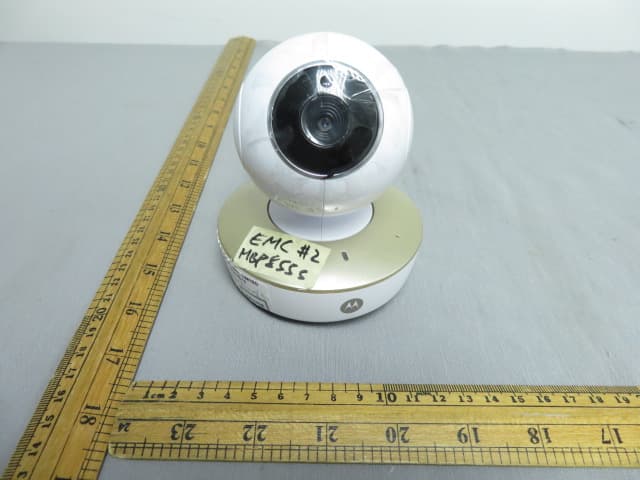
VLJ-MBP855BU
Dec 17, 20205inch Wi-Fi Video Baby Monitor
Equipment Class
DSS - Part 15 Spread Spectrum Transmitter