VLJ-MBP485ABUVideo Baby Monitor
Binatone Electronics International Ltd.
Click to zoom
Application Details
- Equipment Class
- DSS - Part 15 Spread Spectrum Transmitter
- Date of Grant
- Mar 21, 2020
- Application Purpose
- Original Equipment
- Date of Application
- Mar 21, 2020
- Equipment Note
- Video Baby Monitor
- Frequency Range
- 2405.00000000 - 2475.00000000
- Country
- China
Documents & Files
Document Text
Text extracted from the exhibit documents filed with the FCC. Open a document above to read the original.
Users Manual
User’s Guide 5“ Video Baby Monitor Models: MBP485, MBP485-2, MBP485-3, MBP485-4, The features described in this User’s Guide are subject to modifications without prior notice. Welcome... • 1 x Parent Unit • 1 x Baby Unit (Camera) • 1 x Power adapter for the Parent Unit • 1 x Power adapter for the Baby Unit In multi-camera packs, you will find one or more additional camera and power adapter units. to your new Motorola Digital Video Baby Monitor! Thank you for purchasing your new Motorola Digital Video Baby Monitor. Now you can see and hear your baby sleeping in another room or you can monitor your older children in their playroom. Please retain your original dated sales receipt for your records. For warranty service of your Motorola product, you will need to provide a copy of your dated sales receipt to confirm warranty status. Registration is not required for warranty coverage. For product related questions, please call: US and Canada 1-888-331-3383 Email: [email protected] This User's Guide provides you with all the information you need to get the most from your product. Before you can use the Baby Monitor, we recommend you fully charge the battery in the Parent Unit, so that it continues to work if you disconnect it from the power supply to carry it to another location. Please read the Safety Instructions on pages 7-9 before you install the units. Got everything? 1. Display (LCD screen) 2. VIDEO ON/OFF button V Press to turn the LCD screen ON/ OFF (Note: audio is maintained.) 3. TA L K b u t t o n T Press and hold to speak to your baby 4. RESET button (recessed - use small pin) 5. UP button + Normal Mode: Tilt camera Up Menu Mode: Move Up menu options 6. DOWN button - Normal Mode: Tilt camera Down Menu Mode: Move Down menu options 7. MENU button M Press to open / close the Menu options 8. OK button O 9. Micro USB power adapter outlet 10. LEFT button < Normal Mode: Pan camera Left Menu Mode: Move Left along menu options 11. RIGHT button > Normal Mode: Pan camera Right Menu Mode: Move Right along menu options 12. Charging LED: BLUE when mains power connected. 13. Parent Unit ON/OFF LED (Green) 14. Audio Level LEDs (Green, Amber, Red, Red) 15. Volume buttons Press -/+ to decrease/increase Volume level on Parent Unit 16. Power button 0 Press and Hold to turn the Parent Unit ON/OFF 17. Microphone 18. Stand 19.Speaker RESET DC 5V 8 9 7 Overview of the Parent Unit Parent Unit menu icons Signal Level Indication (5 Levels) Night Vision Mode (Video also changes to Black/White) Ta l k M o d e O n Battery Level Indication (4 Levels). Empty cell flashes when battery low. Zoom Level Control (1X, 2X) Brightness Level Control (5 Levels) Lullaby Control (5 Sound Selections) Alarm Setting (6h, 4h, 2h, Off) On status bar, indicates alarm set, and when flashing, that alarm time has been reached or missed. Temperature scale select ( o C / o F) Displays the temperature up to 52 o C/125 o F, and down to 02 o C/35 o F. (Temperatures outside these still show as the maximum or minimum.) Temperature scale select ( o C / o F) Temperature warning limits (Min / Max) Temperature warning alert (On / Off) Camera Control (add , delete ) Indicates camera 1 selected (or 2, 3, 4, as selected). Indicates camera scan on V Set Screen Off Timer (Off , 5 min, 30 min, 60 min) Indicates the screen off timer is set Volume Level Control (8 Levels + Off) Vo l u m e t u r n e d o f f No Baby Unit detected Overview of the Baby Unit 1. POWER ON/OFF switch Slide to turn the Baby Unit on or off. 2. Microphone 3. Infrared LEDs (6) 4. Light Sensor (Night Vision Mode) 5. Camera Lens 6. Power/Link indicator Lights up in green when the Baby Unit is turned on and linking to the Parent Unit. Flashes when the Baby Unit is searching for the Parent Unit, or in pairing mode. Off when the Baby Unit is powered off. 7. PAIR button Press and hold to pair with a Parent Unit. 8. Power Adapter Connector 9. Te m p e r a t u r e S e n s o r 1 2 3 4 5 6 7 8 9 Important guidelines for installing your Baby Monitor • To use your Video Monitor Baby and Parent Units together, you must be able to establish a radio link between them, and the range will be affected by environmental conditions. •Any large metal object, like a refrigerator, a mirror, a filing cabinet, metallic doors or reinforced concrete between the Baby and Parent Unit may block the radio signal. •The signal strength may also be reduced by other solid structures, like walls, or by radio or electrical equipment, such as TVs, computers, cordless or mobile phones, fluorescent lights or dimmer switches. •Use of other 2.4 GHz products, such as wireless networks (Wi-Fi ® routers), Bluetooth™ systems, or microwave ovens, may cause interference with this product, so keep the Baby Monitor away at least 3 feet from these types of products, or turn them off if they appear to be causing interference. •If the signal is weak, try moving the Parent and/or the Baby Unit to different positions in the room(s). 6Table of contents Table of contents 1.Safety Instructions ..................................................................................... 7 2.Getting Started........................................................................................ 10 2.1Baby Unit Power Supply............................................................................ 10 2.2Parent Unit Power Supply ......................................................................... 10 2.3Registration (Pairing) ................................................................................ 12 3.Using the Baby Monitor ........................................................................... 13 3.1Setting up .................................................................................................. 13 3.2 Night Vision Mode ................................................................................... 13 3.3 Talk Mode................................................................................................. 1…
Text truncated - open the document above for the full version.
Cover Letter(s)
QF094234 Page 1 of 1 Revision 0 Authority to Act as Agent Date: 19 November 2019 TUV Rheinland Group 762 Park Avenue Youngsville, NC 27596 To Whom It May Concern: I appoint TUV Rheinland (Shenzhen) Co., Ltd. and Mr. Ryan Yang to act as our agent in the preparation of this application for equipment certification. I certify that submitted documents properly describe the device or system for which equipment certification is sought. I also certify that each unit manufactured, imported or marketed, as defined in the FCC or Industry Canada’s regulations will have affixed to it a label identical to that submitted for approval with this application. For instances where our authorized agent signs the application for certification on our behalf, I acknowledge that all responsibility for complying with the terms and conditions for Certification, as specified by TUV Rheinland Group, still resides with Binatone Electronics International Ltd. / Floor 23A, 9 Des Voeux Road West, Sheung Wan, Hong Kong For TCB applications, We certify that we are not subject to denial of federal benefits, that includes FCC benefits, pursuant to Section 5301 of the Anti-Drug Abuse Act of 1988, 21 U.S.C. 862. Further, no party, as defined in 47 CFR 1.2002 (b), to the application is subject to denial of federal benefits, that includes FCC benefits. Thank you, Agency Agreement Expiration Date: 23 October 2020 By : Karl Heinz Mueller (Print Name) Title : CTO Telephone : +852 2803 7388 On behalf of : Binatone Electronics International Ltd. (Company Name)
Cover Letter(s)
Confidentiality Letter Date: 19 Mar 2020 Subject: Confidentiality Request for FCC ID: VLJ-MBP485ABU and IC ID: 4522A-MBP485ABU Pursuant to FCC 47 CRF 0.457(d) and 0.459 and IC RSP-100, Section 10, the applicant requests that a part of the subject FCC/IC application be held confidential. Type of Confidentiality Requested Exhibit Short Term Permanent Block Diagrams Short Term External Photos Short Term Permanent Internal Photos Short Term Permanent Operation Description/Theory of Operation Short Term Permanent Part List/Tune-Up Procedure Short Term Permanent Schematics Short Term Test Setup Photos Short Term Permanent User’s Manual Binatone Electronics International Ltd. has spent substantial effort in developing this product and it is one of the first of its kind in industry. Having the subject information easily available to "competition" would negate the advantage they have achieved by developing this product. Not protecting the details of the design will result in financial hardship. Permanent Confidentiality: The applicant requests the exhibits listed above as permanently confidential be permanently withheld from public review due to materials that contain trade secrets and proprietary information not customarily released to the public. Short-Term Confidentiality: The applicant requests the exhibits selected above as short term confidential be withheld from public view for a period of 180 days from the date of the Grant of Equipment Authorization and prior to marketing. This is to avoid premature release of sensitive information prior to marketing or release of the product to the public. Applicant is also aware that they are responsible to notify TUV Rheinland in the event information regarding the product or the product is made available to the public. TUV Rheinland will then release the documents listed above for public disclosure pursuant to FCC Public Notice DA 04- 1705. Sincerely, By: Ryan Yang (Signature/Title) (Print name)
External Photos
External Photos of EUT Report No.: CCISE190708501 Model No. : MBP485ABU Page: 1 of 4 External Photos of EUT Report No.: CCISE190708501 Model No. : MBP485ABU Page: 2 of 4 External Photos of EUT Report No.: CCISE190708501 Model No. : MBP485ABU Page: 3 of 4 External Photos of EUT Report No.: CCISE190708501 Model No. : MBP485ABU Page: 4 of 4 --THE END--
ID Label/Location Info
Part Name: Product Label Set_NA Binatone Labeling File Part Name: Baby Unit Revision History: V1 10-Sept-19 Initial release. Rating Label(BU) Material: 50# PET Size : 40 x 22 mm Serial Number - Model Number: 43041 = MBP485A - Produce date: 9D= April/2019 - Serial no. start from ‘000001’ (6 digits) - Code Format: code 128 1) Colour: White background black letters. 2) Size: 30 x 10mm (Gift box). 430419D000001 430419D000001 MODEL: MBP485BU INPUT: DC6V 1000mA Use Only Power Supplies listed in the user’s guide. VLJ-MBP485ABU 4522A-MBP485ABU MBP485ABU FCC ID: IC: HVIN: MADE IN CHINA 430419D000001 MODEL: MBP485ABU INPUT: DC6V 1000mA Use Only Power Supplies listed in the user’s guide. VLJ-MBP485ABU 4522A-MBP485ABU MBP485ABU FCC ID: IC: HVIN: MADE IN CHINA 430419D000001 MODEL: MBP485BU INPUT: DC6V 1000mA Use Only Power Supplies listed in the user’s guide. VLJ-MBP485ABU 4522A-MBP485ABU MBP485ABU FCC ID: IC: HVIN: MADE IN CHINA
Internal Photos
Internal Photos of EUT Report No.: CCISE190708501 Model No. : MBP485ABU Page: 1 of 5 Internal Photos of EUT Report No.: CCISE190708501 Model No. : MBP485ABU Page: 2 of 5 Internal Photos of EUT Report No.: CCISE190708501 Model No. : MBP485ABU Page: 3 of 5 Internal Photos of EUT Report No.: CCISE190708501 Model No. : MBP485ABU Page: 4 of 5 Internal Photos of EUT Report No.: CCISE190708501 Model No. : MBP485ABU Page: 5 of 5 --THE END--
RF Exposure Info
FCC IC: VLJ-MBP485ABU IC: 4522A-MBP485ABU 1 Safety Human Exposure 1.1 Radio Frequency Exposure Compliance 1.1.1 Electromagnetic Fields RESULT: Pass Test Specification Test standard : CFR47 FCC Part 2: Section 2.1091 CFR47 FCC Part 1: Section 1.1310 FCC KDB Publication 447498 v06 FCC KDB Publication 865664 D01 v01r04 FCC KDB Publication 865664 D02 v01r02 RSS-102 Issue 5 March 2015 FCC requirements FCC requirement: Systems operating under the provisions of this section shall be operated in a manner that ensures that the public is not exposed to radio frequency energy level in excess limit for maximum permissible exposure. In accordance with 47 CFR FCC Part 2 Subpart J, section 2.1091 this device has been defined as a mobile device whereby a distance of 20cm normally can be maintained between the user and the device. MPE Calculation Method according to KDB 447498 v06 Power Density: S (mW/cm 2 ) = PG/4πR 2 or EIRP/4πR 2 Where: S = power density (mW/cm 2 ) P = power input to the antenna (mW) G = power gain of the antenna in the direction of interest relative to an isotropic radiator R = distance to the center of radiation of the antenna (cm) The nominal maximum conducted output power specified: 2.4GHz FHSS: 19.00 dBm From the peak RF output power, the minimum mobile separation distance, d=20 cm, as well as the antenna gain (Max. 0.0 dBi for 2.4GHz FHSS), the RF power density can be calculated as below: For 2.4GHz FHSS: S (mW/cm 2 ) = PG/4πR 2 = 0.016 mW/cm 2 Limits for Maximum Permissible Exposure (MPE) according to FCC Part 1.1310: 1.0 mW/cm 2 FCC IC: VLJ-MBP485ABU IC: 4522A-MBP485ABU IC requirements: The EUT shall comply with the requirement of RSS-102 section 2.5.2. Exemption from Routine Evaluation Limits – RF Exposure Evaluation RF exposure evaluation is required if the separation distance between the user and/or bystander and the device’s radiating element is greater than 20 cm, except when the device operates as follows: at or above 300 MHz and below 6 GHz and the source-based, time-averaged maximum e.i.r.p. of the device is equal to or less than 1.31 x 10 -2 ƒ 0.6834 W (adjusted for tune-up tolerance), where ƒ is in MHz; RF exposure evaluation exempted power for 2.4GHz FHSS: 2.670 W The nominal maximum conducted output power specified: 2.4GHz FHSS: 19.00 dBm Antenna Gain: 0.0 dBi for 2.4GHz FHSS The Max. e.i.r.p. for 2.4GHz FHSS: 19.00 dBm = 0.079 W The e.i.r.p. for 2.4GHz FHSS is less than the RF exposure evaluation exempted power. So RF exposure evaluation is not required. “RF Radiation Exposure Statement Caution: This Transmitter must be installed to provide a separation distance of at least 20 cm from all persons.”
Test Report
Shenzhen Zhongjian Nanfang Testing Co., Ltd. Report No: CCISE190708501 Authorized Signature: Bruce Zhang Laboratory Manager T his report details the results of the testing carried out on one sample. T he results contained in this test report do not relate to other samples of the same product and does not permit the use of the CCIS product certification mark. T he manufacturer should ensure that all products in series production are in conformity with the product sample detailed in this report. T his report may only be reproduced and distributed in full. If the product in this report is used in any configuration other than that detailed in the report, the manufacturer must ensure the new system complies with all relevant standards. T his document cannot be reproduced except in full, without prior written approval of the Company. Any unauthorized alteration, forgery or falsification of the content or appearance of this document is unlawful and offenders may be prosecuted to the fullest extent of the law. Unless otherwise stated the results shown in this test report refer only to the sample(s) tested and such sample(s) are retained for 90 days only. TEST REPORT Applicant: Binatone Electronics International Ltd. Address of Applicant: Floor 23A, 9 Des Voeux Road West, Sheung Wan, Hong Kong, China Equipment Under Test (EUT) Product Name: 5” Video Baby Monitor (Baby Unit) Model Name.: MBP485BU Trade mark: motorola FCC ID: VLJ-MBP485ABU Canada IC: 4522A-MBP485ABU HVIN: MBP485ABU Applicable standards: CFR47 FCC Part 15: Subpart C Section 15.247 CFR47 FCC Part 15: Subpart C Section 15.207 CFR47 FCC Part 15: Subpart C Section 15.209 CFR47 FCC Part 15: Subpart B Section 15.107 CFR47 FCC Part 15: Subpart B Section 15.109 RSS-247 Issue 2 February 2017 RSS-Gen Issue 5 April 2018 ICES-003 Issue 6 January 2016 Date of sample receipt: 08 May 2019 Date of Test: 08 May 2019 to 15 July 2019 Date of report issued: 18 July 2019 Test Result: PASS* * In the configuration tested, the EUT complied with the standards specified above. Report No: CCISE190708501 Shenzhen Zhongjian Nanf ang Testing Co., Ltd. Project No.: CCISE1907085 No. B-C, 1/F., Building 2, Laodong No.2 Industrial Park, Xixiang Road, Bao’an District, Shenzhen, Guangdong, China Telephone: +86 (0) 755 2311 8282 Fax: +86 (0) 755 2311 6366 Page 2 of 61 Revision History Rev. Issue Date Report NO. Effect Page Contents 00 18 July 2019 CCISE190708501 ALL Initial Issue Tested by: Date: 08 May 2019 - 15 July 2019 Test Engineer Reviewed by: Date: 18 July 2019 Project Engineer Report No: CCISE190708501 Shenzhen Zhongjian Nanf ang Testing Co., Ltd. Project No.: CCISE1907085 No. B-C, 1/F., Building 2, Laodong No.2 Industrial Park, Xixiang Road, Bao’an District, Shenzhen, Guangdong, China Telephone: +86 (0) 755 2311 8282 Fax: +86 (0) 755 2311 6366 Page 3 of 61 Table of Contents Page 1 SUMMARY OF TEST RESULTS ..................................................................................................... 5 1.1 TEST FACTORY ...................................................................................................................... 6 1.2 MEASUREMENT UNCERTAINTY .............................................................................................. 6 2 GENERAL INFORMATION........................................................................................................... 7 2.1 GENERAL DESCRIPTION OF EUT .............................................................................................. 7 2.2 DESCRIPTION OF TEST MODES ............................................................................................... 9 2.3 BLOCK DIGRAM SHOWING THE CONFIGURATION OF SYSTEM TESTED ........................................10 2.4 DESCRIPTION OF NECESSARY ACCESSORIES AND SUPPORT UNITS .............................................10 2.5 EQUIPMENTS LIST ...............................................................................................................11 3 EMC EMISSION TEST ................................................................................................................12 3.1 CONDUCTED EMISSION MEASUREMENT ................................................................................12 3.2 RADIATED EMISSION MEASUREMENT ....................................................................................18 3.3 RADIATED SPURIOUS EMISSION MEASUREMENT ....................................................................24 4 CONDUCTED SPURIOUS & BAND EDGE EMISSION ....................................................................38 4.1 APPLIED PROCEDURES / LIMIT ..............................................................................................38 4.2 TEST PROCEDURE ................................................................................................................38 4.3 DEVIATION FROM STANDARD ...............................................................................................38 4.4 TEST SETUP.........................................................................................................................38 4.5 EUT OPERATION CONDITIONS ...............................................................................................38 4.6 TEST RESULTS ......................................................................................................................39 5 NUMBER OF HOPPING CHANNEL .............................................................................................43 5.1 APPLIED PROCEDURES / LIMIT ..............................................................................................43 5.2 TEST PROCEDURE ................................................................................................................43 5.3 DEVIATION FROM STANDARD ...............................................................................................43 5.4 TEST SETUP....................................................................................................…
Text truncated - open the document above for the full version.
Test Setup Photos
Report No: CCISE190708501 Shenzhen Zhongjian Nanf ang Testing Co., Ltd. Project No.: CCISE1907085 No. B-C, 1/F., Building 2, Laodong No.2 Industrial Park, Xixiang Road, Bao’an District, Shenzhen, Guangdong, China Telephone: +86 (0) 755 2311 8282 Fax: +86 (0) 755 2311 6366 Page 59 of 61 11 APPENDIX - PHOTOS OF TEST SETUP Radiated SPURIOUS EMISSION SET-UP PHOTOS, 30MHz ~ 1GHz Radiated SPURIOUS EMISSION SET-UP PHOTOS, 1GHz ~ 25GHz Report No: CCISE190708501 Shenzhen Zhongjian Nanf ang Testing Co., Ltd. Project No.: CCISE1907085 No. B-C, 1/F., Building 2, Laodong No.2 Industrial Park, Xixiang Road, Bao’an District, Shenzhen, Guangdong, China Telephone: +86 (0) 755 2311 8282 Fax: +86 (0) 755 2311 6366 Page 60 of 61 CONDUCTED EMISSION SET-UP PHOTOS Report No: CCISE190708501 Shenzhen Zhongjian Nanf ang Testing Co., Ltd. Project No.: CCISE1907085 No. B-C, 1/F., Building 2, Laodong No.2 Industrial Park, Xixiang Road, Bao’an District, Shenzhen, Guangdong, China Telephone: +86 (0) 755 2311 8282 Fax: +86 (0) 755 2311 6366 Page 61 of 61 RADIATED EMISSION SET-UP PHOTOS, 30MHz ~ 1GHz RADIATED EMISSION SET-UP PHOTOS, Above 1GHz ※※※※※END OF THE REPORT※※※※※
Contact Information
Applicant
Sam Lee(Product Director)
Technical Contact
Test Firm
JianYan Testing Group Shenzhen Co., Ltd.Bruce Zhang
[email protected]+86 (0) 755 23118282
Technical Specifications
| # | Rule Parts | Frequency Range | Power Output |
|---|---|---|---|
| 1 | 15C | 2.40 GHz - 2.48 GHz | 69.80 mW |
Other Applications from Binatone Electronics International Ltd.

VLJ-NV531BU
Jul 03, 2022Video Baby Monitor
Equipment Class
DSS - Part 15 Spread Spectrum Transmitter
VLJ-MH002W
Mar 02, 2021Bluetooth Headset
Equipment Class
DSS - Part 15 Spread Spectrum Transmitter
VLJ-ST600
Feb 09, 20215-in-1 Nursery Humidifier
Equipment Class
DSS - Part 15 Spread Spectrum Transmitter
VLJ-SP025
Feb 01, 2021Portable Bluetooth Music Speaker
Equipment Class
DCD - Part 15 Low Power Transmitter Below 1705 kHz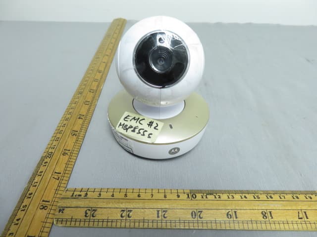
VLJ-MBP855BU
Dec 17, 20205inch Wi-Fi Video Baby Monitor
Equipment Class
DSS - Part 15 Spread Spectrum Transmitter