VLJ80-8230-001.9GHz Digital Modulation Baby Monitor - Baby Unit
Binatone Electronics International Ltd.
Click to zoom
Application Details
- Equipment Class
- PUB - Part 15 Unlicensed PCS Base Station
- Date of Grant
- Jun 16, 2011
- Application Purpose
- Original Equipment
- Date of Application
- Jun 16, 2011
- Equipment Note
- 1.9GHz Digital Modulation Baby Monitor - Baby Unit
- Frequency Range
- 1921.53600000 - 1928.44800000
- Country
- China
Documents & Files
Document Text
Text extracted from the exhibit documents filed with the FCC. Open a document above to read the original.
Users Manual
Userís Guide MBP11 Baby Monitor The features described in this user's guide are subject to modifications without prior notice. Welcome... to your new Motoro la Baby Monitor! Thank you for purchasing the MBP11. Now you c an hear your baby sleeping in the other room. Please retain your original dated sales receipt for your records. For warranty service of your Motorola product, you will need to provide a copy of your dated sales receipt to confirm warranty status. Registration is not required for warranty coverage.For product-related questions, please call: US and Canada 1-888-331-3383On the Web: www.motorola.com This User's Guide provides you with all the information you need to get the most from your product.Before you can use the baby monitor, we recommend you insert and fully charge the battery in the parent unit, so that it continues to work if you disconnect it from the mains power to carry it to another location. Please read the Safety Instructions on page 6 before you install the units.Got everything?ï 1 x Parent unit (MBP11PU)ï 1 x Baby unit (MBP11BU)ï 1 x Rechargeable Ni-MH battery pack for the Parent unitï 1 x Power adapter for the Parent unitï 1 x Power adapter for the Baby unit Overview of your Parent unit 5 6 4213 1 Sound Level LED 3 GREEN and 2 RED LEDs turn on and off in real time to indicate the noise level in baby's room. When audio is being picked up by microphone of baby unit, the LEDs light up to in indicate audio level with reference to the sensitivity setting. The more LEDs light up, the stronger the sound is.No LED lights up means the sound level in baby's room does not exceed the thresholds set through the parent unit.The LEDs are also used for indicating the speaker volume setting on parent unit. The louder you set the speaker volume, the more LEDs light up. 2 Link Indicator On when the parent unit is powered on and linked to the baby unit.Flashes when the parent unit is out of range from baby unit.Off when the parent unit is powered off. 3Power Press and hold to power on/off the parent unit. 4 Volume +Press to increase the speaker volume. 5Volume - Press to decrease the speaker volume. 6 Charging Indicator On steadily when in charging mode. Flashes when low battery is detected.NOTEOff even if connected with power adapter but without battery pack installed. Overview of your Baby unit Important guidelines for installing our Baby Monitorï To use your baby unit and parent unit together, you must be able to establish a radio link between them, and the range will be affected by environmental conditions. ï Any large metal object, like a refrigerator, a mirror, a filing cabinet, a me tallic doors or reinforced concrete, between the baby and parent unit may block the radio signal. ï The signal strength may also be reduced by other solid structures, like walls, or by radio or electrical equipment, such as TV's, computers, cordless or mobile phones, fluorescent lights or dimmer switches. ï If the signal is poor, try moving the parent and/or the baby unit to different positions in the rooms. ï If the signal is poor, try moving the parent and/or the baby unit to different positions in the rooms. 1 Power Indicator On when the parent unit is switched on. Off when the parent unit is switched off. 2Power Press and hold to power on/off the baby unit. 12 5 1. SAFETY INSTRUCTIONS ................................... 62. GETTING STARTED............................................ 7 2.1 Baby unit power supply .......................................72.2 Parent unit battery installation.............................72.3 Belt clip on parent unit and baby unit ..................8 3. USING YOUR BABY MONITOR.......................... 9 3.1 Power on/off the parent unit................................93.2 Power on/off the baby unit ..................................93.3 Adjust speaker volume........................................9 4. DISPOSAL OF THE DEVICE (ENVIRONMENT)............................................... 10 5. CLEANING......................................................... 106. TROUBLESHOOTING ....................................... 117. GENERAL INFORMATION................................ 128. TECHNICAL SPECIFICATIONS........................ 16 6 SAFETY INSTRUCTIONS 1. SAFETY INSTRUCTIONS WARNING: STRANGULATION HAZARD - Keep the adapter cord out of baby's reach.NEVER place the baby monitor or its cord within the crib. Secure the cord some distance away from baby's reach.Never use extension cords with AC Adapters. Only use the AC Adapters provided.This baby monitor is complian t with all relevant standards regarding electromagnetic fi elds and is, when handled as described in the User's Guide, safe to use. Therefore, always read the instructions in this User's Guide carefully before using the device.ï Determine a location for the baby monitor that will provide the best audio reception of your baby in his crib. ï Place the baby monitor on a flat surface, such as a dresser, bureau, or shelf. ï NEVER place the baby monitor or its cord within the crib. ï Secure the cord to the wall to keep cord away from the baby's reach. ï Adult assembly is required. Keep small parts away from children when assembling. ï This product is not a toy. Do n't allow children to play with it. ï This baby monitor is not a substitute for responsible adult supervision. ï Keep this User's Guide for future reference.ï Do not cover the baby monitor with a towel or blanket.ï Never use extension cords with power adapters. Only use the power adapters provided. ï Test this monitor and all its functions so that you are familiar with it pr ior to actual use. ï Do not use the baby monitor near water.ï Do not install the baby monitor near a heat source.ï Only use the chargers and power adapters provided. Do not use other chargers or power adapters as this may damage the device and battery pack. ï Only insert battery pack of the same type.ï Do not touch the plug contacts with sharp or metal objects. CAUTIONRisk of explosi…
Text truncated - open the document above for the full version.
Cover Letter(s)
Binatone Electronics International Limited Floor 23A, 9 Des Voeux Road West, Hong Kong Tel: (852) 2802 7388 Fax: (852) 2802 8138 _______________________________________ . Appendix B1 Letter of Agency for FCC Certification May. 20, 2011 To whom it may concern, Letter of Agency I, an officer of Binatone Electronics International Limited do hereby authorize Intertek Testing Services (Mr. Ken Sit/ Mr. Melvin Nip) to act on our behalf in front of the Federal Communications Commission with respect to all matters relating to certification of equipment under Part 15 and/or Part 95 of the FCC Rules until further notice. I further certify that no party (as defined in §1.2002(b) of CFR 47, 2004) to this application, including myself, is subject to a denial of federal benefits, that includes FCC benefits, pursuant to Section 5301 of the Anti-Drug Abuse Act of 1988, 21 U.S.C., 862. Regards, __________________ Paul Tsui Product Operation Director
Cover Letter(s)
Binatone Electronics International Limited Floor 23A, 9 Des Voeux Road West, Hong Kong Tel: (852) 2802 7388 Fax: (852) 2802 8138 _______________________________________ . May. 20, 2011 To whom it may concern, Request for Permanent Confidentiality Under FCC Part 15 Certification FCC ID: VLJ80-8230-00 Request is hereby submitted by Binatone Electronics International Limited to withhold permanently from public review certain portions of the application for equipment certification for the referenced FCC identifiers. This request for confidentiality is made pursuant to 47 CFR § 0.457(d) and 0.459 of the FCC Rules. In particular, the following sections of the application are to be kept permanently confidential and Binatone Electronics International Limited reserves the right to discern which parties can obtain access to these information: Schematics Detailed Block diagrams Detailed Operational/Functional Description The rationale for request for confidentiality is as followings: This information represents intellectual property of Binatone Electronics International Limited and it is subject to competition. We have invested considerable time and materials in research and development to produce the referenced product. Disclosure of the permanently confidential portions of this application to competitors would not only give them significant competitive advantages in developing similar products, but would also disclose successful implementation of unpublished, leading edge technology developed by us. If you have questions or need further information, please contact the undersigned. Regards, __________________ Paul Tsui Product Operations Director
External Photos
INTERTEK TESTING SERVICES External Photos FCC ID: VLJ80-8230-00 IC: 4522A-80823000 external photos - 1 of 2 HK11050016 Job Number HK11050016 Job Number INTERTEK TESTING SERVICES External Photos FCC ID: VLJ80-8230-00 IC: 4522A-80823000 external photos - 2 of 2
ID Label/Location Info
S/N : Use only power supplies listed in the user manual Input : DC6V Model : MBP16 450mA Made in China S/N : Use only power supplies listed in the user manual Model : MBP16 Input : DC6V 450mA Made in China S/N : Use only power supplies listed in the user manual Input : DC6V Model : MBP11 450mA Made in China S/N : Use only power supplies listed in the user manual Model : MBP11 Input : DC6V 450mA Made in China MBP11&16 LBL S/N : Model : MBP16PU DC 6V 450mA Made in China IC : 4522A-80823001 FCC ID : VLJ80-8230-01 S/N : Model : MBP16BU Made in China IC : 4522A-80823000 FCC ID : VLJ80-8230-00 DC 6V 450mA S/N : Model : MBP11PU DC 6V 450mA Made in China IC : 4522A-80823001 FCC ID : VLJ80-8230-01 S/N : Model : MBP11BU Made in China IC : 4522A-80823000 FCC ID : VLJ80-8230-00 DC 6V 450mA Engraved in glossy Raised 0.3mm Lable paper : 28 x 10 mm Engraved in glossy Raised 0.3mm Lable paper : 34 x 19 mm MBP11 US/CA PU MBP11 US/CA BU Engraved in glossy Raised 0.3mm Engraved in glossy Raised 0.3mm Engraved in glossy Raised 0.3mm Engraved in glossy Raised 0.3mm Engraved in glossy Raised 0.3mm Engraved in glossy Raised 0.3mm MBP11 EU/UK PU MBP11 EU/UK BU MBP16 EU/UK PU MBP16 EU/UK BU MBP16 US/CA PU MBP16 US/CA BU Engraved in glossy Raised 0.15mm MBP11 / 16 EU/UK/US/CA PU BATTERY DOOR Lable paper : 28 x 10 mm Lable paper : 34 x 19 mm Lable paper : 34 x 19 mm Lable paper : 28 x 10 mm Lable paper : 28 x 10 mm Lable paper : 34 x 19 mm
Internal Photos
INTERTEK TESTING SERVICES Internal Photos FCC ID: VLJ80-8230-00 IC: 4522A-80823000 Internal photos - 1 of 3 Internal Photo - 1 Internal Photo - 2 INTERTEK TESTING SERVICES Internal Photos FCC ID: VLJ80-8230-00 IC: 4522A-80823000 Internal photos - 2 of 3 Internal Photo - 3 Internal Photo - 4 INTERTEK TESTING SERVICES Internal Photos FCC ID: VLJ80-8230-00 IC: 4522A-80823000 Internal photos - 3 of 3 Internal Photo - 5
RF Exposure Info
INTERTEK TESTING SERVICES FCC ID: VLJ80-8230-00 RF exposure info - 1 of 1 For Maximum Permissible Exposure (MPE) evaluation of the baby unit, the maximum power density at 20 cm from this mobile transmitter shall be less than the General Population / Uncontrolled MPE limit in OET Bulletin 65. For the baby unit of tested model of MBP16BU, the maximum field strength measured (FS) was 118.6 dBμV/m. The distance (D) between the antenna and the equipment under test (EUT) was 3 meters. And the maximum source-based time- averaging duty factor in four parent units operation is 20.8%. From these data, the exposed power density at a distance (R) of 20cm from the center of radiation of the antenna can be calculated according to OET Bulletin 65 as follow: The radiated power (EIRP) = (FS*D) 2 / 30 = 217.33 mW The radiated (EIRP) source-based time-averaging output power = (217.33 * 0.208) mW = 45.20 mW The power density at 20 cm from the antenna = EIRP / 4πR 2 = 0.0090 mW cm -2 In the frequency range of 1,500 - 100,000MHz, the MPE limit is 1.0 mWcm -2 for general population and uncontrolled exposure. As the measured power density at 20cm from the transmitter is lower than the MPE limit, the compliance to the MPE limit can be ensured by indicating the minimum 20cm separation between the transmitter's radiating structures and body of the user or nearby persons. The following RF exposure statement is proposed to be included in the user manual: “ FCC RF Radiation Exposure Statement Caution: To maintain compliance with the FCC’s RF exposure guidelines, place the baby unit at least 20cm from nearby persons.”
Test Report
INTERTEK TESTING SERVICES 26dB Emission Bandwidth Plots FCC ID: VLJ80-8230-00 bw - 1 of 1 A0 Baby unit, Lowest channel, Traffic carrier Baby unit, Highest channel, Traffic carrier
Test Report
Report no.: HK11050016-1 Baby Unit Ten Pao Adaptor Talk Mode AC Mains Ctrl No.: N/A 6DB AC 150 kHz30 MHz dBμV dBμV 1 PK CLRWR 2 AV CLRWR SGL TDS RBW 9 kHz MT 1 s PREAMP OFFAtt 10 dB AUTO 1 MHz10 MHz 0 10 20 30 40 50 60 70 80 90 100 CF15MAV CF15MQP Date: 20.MAY.2011 19:07:40
Test Report
INTERTEK TESTING SERVICES Unwanted Emission Inside The Sub-Band Plots FCC ID: VLJ80-8230-00 inband - 1 of 1 A0 Baby unit, Lowest channel, Traffic carrier Baby unit, Highest channel, Traffic carrier
Test Report
INTERTEK TESTING SERVICES Peak Transmit Power Plots FCC ID: VLJ80-8230-00 IC: 4522A-80823000 peaktp - 1 of 2 A0 Baby unit, Lowest channel, Traffic carrier Baby unit, Middle channel, Traffic carrier INTERTEK TESTING SERVICES Peak Transmit Power Plots FCC ID: VLJ80-8230-00 IC: 4522A-80823000 peaktp - 2 of 2 A0 Baby unit, Highest channel, Traffic carrier
Test Report
INTERTEK TESTING SERVICES Power Spectral Density Plots FCC ID: VLJ80-8230-00 psd - 1 of 1 A0 Baby unit, Lowest channel, Traffic carrier Baby unit, Highest channel, Traffic carrier
Test Report
- The test report only allows to be revised within the retention period unless further standard or the requirement was noticed. - This report is for the exclusive use of Intertek's Client and is provided pursuant to the agreement between Intertek and its Client. Intertek's responsibility and liability are limited to the terms and conditions of the agreement. Intertek assumes no liability to any party, other than to the Client in accordance with the agreement, for any loss, expense or damage occasioned by the use of this report. Only the Client is authorized to permit copying or distribution of this report and then only in its entirety. Any use of the Intertek name or one of its marks for the sale or advertisement of the tested material, product or service must first be approved in writing by Intertek. The observations and test results in this report are relevant only to the sample tested. This report by itself does not imply that the material, product, or service is or has ever been under an Intertek certification program. Intertek Testing Services Hong Kong Ltd. 2/F., Garment Centre, 576 Castle Peak Road, Kowloon, Hong Kong. Tel: (852) 2173 8888 Fax: (852) 2785 5487 Website: www.hk.intertek-etlsemko.com Binatone Electronics International Limited Application For 47 CFR Part 15 Certification RSS-213 Issue 2 Equipment Certification Unlicensed Personal Communication Service Devices/ 2 GHz License-exempt Personal Communications Service Devices (Baby Unit) FCC ID: VLJ80-8230-00 Model: MBP11BU, MBP16BU IC: 4522A-80823000 Model: MBP11BU, MBP16BU Test Report Number: HK11050016-1 Issue Date: June 01, 2011 MN/ cl INTERTEK TESTING SERVICES Test Report Number: HK11050016-1 Page 1 of 53 FCC ID: VLJ80-8230-00 IC: 4522A-80823000 Table of Contents 1.0 Summary of Test Results........................................................................................ 4 2.0 General Description................................................................................................. 7 2.1 Product Description ................................................................................................. 7 2.2 Technical Description .............................................................................................. 7 2.3 Test Methodology.................................................................................................... 8 2.4 Test Facility............................................................................................................. 8 3.0 System Test Configuration.................................................................................... 10 3.1 Justification ........................................................................................................... 10 3.2 Conducted Emission Test Configuration ................................................................ 11 3.3 Conducted Monitoring and Operational Test Configuration.................................... 11 3.4 EUT Exercising Software....................................................................................... 11 3.5 Details of EUT and Description of Peripherals....................................................... 12 3.6 Measurement Uncertainty ..................................................................................... 12 4.0 Measurement Results............................................................................................ 14 4.1 Antenna Requirement........................................................................................... 14 4.2 Digital Modulation Techniques............................................................................... 14 4.3 Emission Bandwidth.............................................................................................. 15 4.4 Directional Gain of the Antenna ............................................................................. 15 4.5 Peak Transmit Power ............................................................................................ 16 4.6 Power Spectral Density ......................................................................................... 17 4.7 Automatic Discontinuation of Transmission............................................................ 17 4.8 Unwanted Emission Inside the Sub-Band .............................................................. 18 4.9 Emissions Outside the Sub-Band .......................................................................... 19 4.9.1 Radiated Emissions Configuration Photographs ................................................. 20 4.9.2 Radiated Emissions Data ................................................................................... 20 4.9.3 Field Strength Calculation................................................................................... 27 4.9.4 Average Factor Calculation and Transmitter ON Time Measurements ................ 28 4.10 Radiated Emissions from Receiver ...................................................................... 28 4.10.1 Radiated Emission Configuration Photographs ................................................. 29 4.10.2 Radiated Emissions Data ................................................................................. 29 4.11 AC Power Line Conducted Emissions ................................................................. 32 4.11.1 AC Power Line Conducted Emissions Configuration Photographs .................... 33 4.11.2 AC Power Line Conducted Emissions Data ...................................................... 33 4.12 Radio Frequency Radiation Exposure.................................................................. 34 4.13 Radio Frequency Exposure Compliance.............................................................. 34 4.14 Frame Repetition Stability .................................................................................. 35 4.15 Frame Period and Jitter ...................................................................................... 36 4.16 Carrier Frequency …
Text truncated - open the document above for the full version.
Test Setup Photos
INTERTEK TESTING SERVICES The Worst Case Configuration Photographs – Mode: Transmission FCC ID: VLJ80-8230-00 IC: 4522A-80823000 config photos (radiated emission – baby unit) - 1 of 1 Radiated Emission – Baby Unit (with adaptor “Ten Pao”) Front View Rear View INTERTEK TESTING SERVICES The Worst Case Configuration Photographs – Mode: Talk FCC ID: VLJ80-8230-00 IC: 4522A-80823000 config photos (conducted emission) - 1 of 2 Conducted Emission (with adaptor “Ten Pao”) Front View Right Side View INTERTEK TESTING SERVICES The Worst Case Configuration Photographs – Mode: Talk FCC ID: VLJ80-8230-00 IC: 4522A-80823000 config photos (conducted emission) - 2 of 2 Conducted Emission (with adaptor “Ten Pao”) Left Side View
Contact Information
Applicant
Sam Lee(Product Director)
Technical Contact
Intertek Testing Services Hong Kong LtdMelvin Nip
[email protected]2173 8888
Flat D 5/F Garment Centre · Kowloon · Hong Kong
Non-Technical Contact
Intertek Testing Services Hong Kong LtdMelvin Nip
[email protected]2173 8888
Test Firm
Intertek Testing Services Hong Kong Ltd.Billy Chow
Technical Specifications
| # | Rule Parts | Frequency Range | Power Output |
|---|---|---|---|
| 1 | 15D | 1.92 GHz - 1.93 GHz | 97.00 mW |
Other Applications from Binatone Electronics International Ltd.

VLJ-NV531BU
Jul 03, 2022Video Baby Monitor
Equipment Class
DSS - Part 15 Spread Spectrum Transmitter
VLJ-MH002W
Mar 02, 2021Bluetooth Headset
Equipment Class
DSS - Part 15 Spread Spectrum Transmitter
VLJ-ST600
Feb 09, 20215-in-1 Nursery Humidifier
Equipment Class
DSS - Part 15 Spread Spectrum Transmitter
VLJ-SP025
Feb 01, 2021Portable Bluetooth Music Speaker
Equipment Class
DCD - Part 15 Low Power Transmitter Below 1705 kHz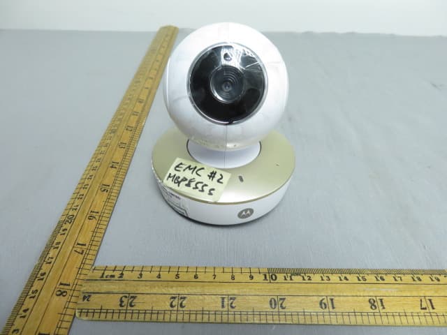
VLJ-MBP855BU
Dec 17, 20205inch Wi-Fi Video Baby Monitor
Equipment Class
DSS - Part 15 Spread Spectrum Transmitter