VMI4KBUDDY4K Video Doorbell
Swann Communications U.S.A. Inc.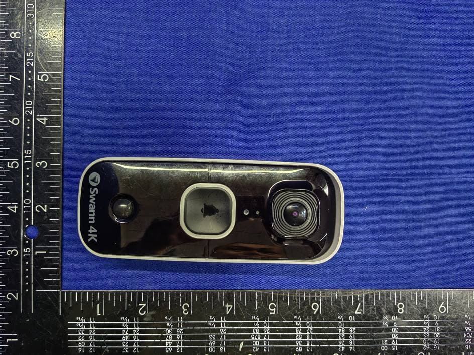
Click to zoom
Application Details
- Equipment Class
- DTS - Digital Transmission System
- Date of Grant
- Aug 23, 2023
- Application Purpose
- Original Equipment
- Date of Application
- Aug 23, 2023
- Equipment Note
- 4K Video Doorbell
- Frequency Range
- 2412.00000000 - 2462.00000000
- Country
- United States
Documents & Files
Document Text
Text extracted from the exhibit documents filed with the FCC. Open a document above to read the original.
Users Manual
1 EN SwannBuddy™ 4K Video Doorbell Timbre con Cámara de Video 4K SwannBuddy™ Sonnette vidéo SwannBuddy™ 4K Campanello video SwannBuddy™ 4K SwannBuddy™ 4K-Video-Türklingel EN QUICK START GUIDE ES GUÍA DE INICIO RÁPIDO FR GUIDE DE DÉMARRAGE RAPIDE IT GUIDA RAPIDA DE SCHNELLSTARTANLEITUNG 2 EN SWANNBUDDY OVERVIEW Night detection sensor Infrared LEDs (for night vision) Microphone Speaker (bottom) Doorbell button FRONT BACK Wire terminals (for optional external power source 12- 24V AC transformer) For more information about the SwannBuddy external power wiring, scan the QR code below: Rubber cover Pull open from the bottom to access: — SET (pair) button — RST (power off) button — microSD card slot 32GB card pre-installed, max.128GB card supported — USB-C charging port Passive infrared motion sensor Light ring QR code (for device pairing) Mounting bracket slots Remove protective film before use 3 EN CHIME OVERVIEW FRONTBACK SpeakerDouble-sided mounting tape area Battery compartment SET buttonLED indicator Installing Batteries 1. Remove the battery compartment cover by sliding it down. 2. Insert two new, high quality "AA" alkaline batteries (supplied), matching the polarity markings (+ and -) shown inside the battery compartment. 3. Replace the battery compartment cover. BATTERY SAFETY INFORMATION • Replace batteries at the same time. Do not mix new and old batteries or battery types (for example, alkaline and lithium batteries). • Keep batteries out of reach of children. • Dispose of used batteries promptly in accordance with local regulations. 4 EN GET STARTED Before using the SwannBuddy for the first time, fully charge it with the included USB-C charging cable. 1 Open the rubber cover on the back of the SwannBuddy. 2 Insert the smaller end of the charging cable into the USB-C port and the larger end into a USB wall charger, such as the USB power adapter that came with your smartphone, as shown on the right. 3 The light ring around the doorbell button on the front of the SwannBuddy will glow solid blue during charging and turn off once the SwannBuddy is fully charged. 4 Actual charging times may vary depending on the USB power adapter used and the remaining battery level. A full charge may take up to six hours. Charging the SwannBuddy Solid blue during charging To USB Wall Charger 5 EN Pairing the Chime with the SwannBuddy You can pair the Chime with the SwannBuddy by following the steps below. 1 Press and hold the SET button on the Chime for about 3 seconds until the LED indicator starts blinking blue, and you hear a voice prompt “Setup is in progress. Press the Doorbell to connect.” 2 Press and hold the Doorbell button on the SwannBuddy for 3 seconds. The LED indicator on the Chime immediately turns off, confirming successful pairing. • Note: If you fail to complete pairing within 90 seconds, the LED indicator on the Chime will automatically turn off. Repeat steps 1-2 to pair the Chime again. 3 To test the Chime, simply press the Doorbell button on the SwannBuddy. You will hear the “Ding Dong” melody. Changing the Chime melody Once the Chime is paired with the SwannBuddy, you can change the Chime’s default “Ding Dong” melody by following the steps below. 1 Press the SET button on the Chime once to select the next melody in the sequence. 2 Press the Doorbell button on the SwannBuddy to listen to the selected melody. 3 Repeat steps 1-2 until you hear a melody you like. There are six melodies to choose from. GET STARTED SET buttonLED indicator 6 EN DOWNLOAD THE SWANN SECURITY APP 1 Download the latest version of the Swann Security app from the Google Play™ Store or Apple App Store® on your Android or iOS mobile device. Simply search for "Swann Security". Or, you can scan the QR code below to get the app. 2 Open the app and create your Swann Security account by tapping “Not yet registered? Sign Up” at the bottom of the screen. Then, activate your Swann Security account by confirming the verification email sent to your registered email address. 7 EN SET UP THE SWANNBUDDY Launch the Swann Security app and sign in. Tap the Pair Device button on the screen (or tap the menu icon in the top left and select Pair Device). The app will now guide you through the pairing process to set up the SwannBuddy with your Wi-Fi network. Please note that the camera is only compatible with the 2.4GHz network. If your router is using the 5GHz band, ensure that it is operating in mixed mode. 8 EN The SwannBuddy can be mounted on the surface using the supplied mounting bracket as shown below. Before mounting the SwannBuddy, ensure that the desired installation location has good, reliable Wi-Fi reception. Using the app, try streaming live video from the SwannBuddy there. If you don’t experience any video streaming issues, you’ve found a suitable place for your device. If you find that the Wi-Fi signal is weak or out of range, consider installing a Wi-Fi range extender to enhance the Wi-Fi coverage of your existing network. MOUNT THE SWANNBUDDY Installing the bracket • If mounting on a wooden surface, screw the bracket directly to the surface. • If mounting on a masonry surface or drywall, insert wall plugs before screwing the bracket to the surface. • If mounting on a window panel, use the supplied double-sided (rectangular) tape. Peel off liner on one side of the tape and apply it to the back of the bracket. Peel off opposite liner, then using a firm amount of pressure, press the bracket against the window panel for 60 seconds. Allow 24 hours for the adhesive to fully cure before attaching the SwannBuddy to the bracket. • For screw installation only: If there is a gap between the wall and bracket, use the supplied bracket foam tape to fill it. Attaching the SwannBuddy Align the mounting bracket slots on the back of the SwannBuddy with the mounted bracket, and then slide it down. Tighten the anti-tamper screw with a small Philips ® screwdriver to secure in place. Anti-tamper screw hole Anti-tamper screw Suggested instal…
Text truncated - open the document above for the full version.
Attestation Statements
Rev 1/26/2023 Swann Communications U.S.A. Inc. Federal Communications Commission Authorization and Evaluation Division 7435 Oakland Mills Road Columbia, MD 21046 USA Date: 8-5-2023 Ref: Attestation Statements Part 2.911(d)(5)(i) Filing FCC ID: VMI4KBUDDY Swann Communications U.S.A. Inc. ("the applicant")certifies that the equipment for which authorization is sought is not“covered” equipment prohibited from receiving an equipment authorization pursuant to section 2.903 of the FCC rules. Sincerely, (Applicantsignature) (Applicant printed name) James Cain/VP Quality Assurance Rev 1/26/2023 Swann Communications U.S.A. Inc. Federal Communications Commission Authorization and Evaluation Division 7435 Oakland Mills Road Columbia, MD 21046 USA Date: 8-5-2023 Ref: Attestation Statements Part 2.911(d)(5)(ii) Filing FCC ID: VMI4KBUDDY Swann Communications U.S.A. Inc. (“the applicant”) certifies that, as of the date of the filing of the application, the applicant is not identified on the Covered List(as a specifically named entity or any of its subsidiaries or affiliates) as an entity producing “covered” equipment. Sincerely, (Applicant signature) (Applicant printed name) James Cain/VP Quality Assurance
Attestation Statements
Rev 1/26/2023 Swann Communications U.S.A. Inc. 12636 Clark Street Santa Fe Springs California United States 90670 Federal Communications Commission Authorization and Evaluation Division 7435 Oakland Mills Road Columbia, MD 21046 USA Date: 7- 26-2023 Ref: Attestation Statements Part 2.911(d)(7) Filing FCC ID or Grantee Code: VMI4KBUDDY Swann Communications U.S.A. Inc. (“the applicant”) certifies that, as of the date of the filing of the application, we designate ourselves as the U.S. agent for service of process. Designated U.S. Agent Information: FRN: 0024573800 Company Name: Swann Communications U.S.A. Inc. Address: 12636 Clark Street Santa Fe Springs California United States 90670 Contact Name: James Cain Contact Person: Vice President Quality Assurance Tel.: 15627772551 Email: [email protected] Sincerely, Swann Communications U.S.A. Inc. James Cain [Applicant signature]
Cover Letter(s)
Swann Communications U.S.A. Inc. Date: 2023-8-5 To: Federal Communications Commission 7435 Oakland Mills Road Columbia, MD FCC ID: VMI4KBUDDY To Whom It May Concern: This letter is to ascertain thatSwann Communications U.S.A. Inc./ 12636 Clark Street Santa Fe Springs California United States 90670 EUT:4K Video Doorbell MODEL No.: SWIFI-4KBUDDY Has been the units used for conducting FCC compliance testing, the SDoC part Have be tested by EMTEK (SHENZHEN) CO., LTD. If you have any question or concerns, pls. contact us. Sincerely, Client’s signature : Client’s name / title :James Cain/VP Quality Assurance Contact information / address: Swann Communications U.S.A. Inc. /12636 Clark Street Santa Fe Springs California United States 90670
Cover Letter(s)
Rev 11/20/07 Swann Communications U.S.A. Inc. Federal Communications Commission Authorization and Evaluation Division Confidentiality Request regarding application for certification of FCC ID: VMI4KBUDDY Pursuant to Sections 0.457 and 0.459 of the Commission’s Rules, we hereby request confidential treatment of information accompanying this application as outlined below: Exhibit Type File Name Block Diagram, Schematics, Operational Description, Block Diagram, Schematics, Operational Description, The above materials contain trade secrets and proprietary information not customarily released to the public. The public disclosure of these materials may be harmful to the applicant and provide unjustified benefits to its competitors. Client’s name / title :James Cain/VP Quality Assurance Contact information / address: Swann Communications U.S.A. Inc. /12636 Clark Street Santa Fe Springs California United States 90670
Cover Letter(s)
Swann Communications U.S.A. Inc. Federal Communications Commission Authorization and Evaluation Division 1435 Oakland Mills Road Columbia, MD 21046 Date: 2023-8-5 SUBJECT: FCC Application for FCC ID: VMI4KBUDDY To Whom It May Concern: We, the undersigned, hereby authorize Lisa Wangat EMTEK (SHENZHEN) CO., LTD.on our behalf, to apply to the Federal Communications Commission on our equipment. Any and all acts carried out byEMTEK (SHENZHEN) CO., LTD.on our behalf shall have the same effect as acts of our own. This is to advise that we are in full compliance with the Anti- Drug Abuse Act. We, the applicant, are not subject to a denial of federal benefits pursuant to Section 5301 of the Anti-Drug Act of 1988, 21 USC853a, and no party to the application is subject to a denial of federal benefits pursuant to that section. Regards, Client’s name / title :James Cain/VP Quality Assurance Contact information / address: Swann Communications U.S.A. Inc. /12636 Clark Street Santa Fe Springs California United States 90670
External Photos
EUT EXTERNAL PHOTOGRAPHS ----------------The end----------------
Internal Photos
EUT INTERNAL PHOTOGRAPHS WiFi Module 433.92MHz Module WiFi Antenna 433.92MHz Antenna ----------------The end----------------
RF Exposure Info
FCC ID : VMI4KBUDDY RF EXPOSURE EVALUATION According to FCC 1.1310: The criteria listed in the following table shall be used to evaluate the environment impact of human exposure to radio frequency (RF) Radiation as specified in §1.1307(b) Limits for Maximum Permissible Exposure (MPE) Frequency Range(MHz) Electric Field Strength(V/m) Magnetic Field Strength(A/m) Power Density(mW/cm 2 ) Average Time (A) Limits for Occupational/Control Exposures 300-1500 -- -- F/300 6 1500- 100000 -- -- 5 6 (B) Limits for General Population/Uncontrol Exposures 300-1500 -- -- F/1500 6 1500- 100000 -- -- 1 30 11.1 Friis transmission formula: Pd= (Pout*G)\ (4*pi*R 2 ) Where Pd= Power density in mW/cm 2 Pout=output power to antenna in mW G= Numeric gain of the antenna relative to isotropic antenna Pi=3.1416 R= distance between observation point and center of the radiator in cm Pd the limit of MPE, 1mW/cm 2 ,If we know the maximum gain of the nd total power input to the antenna, through the calculation, we will know the distance where the MPE limit is reached. RF Exposure Information: The radiated output power of this device meets the limits of FCC/IC radio frequency exposure limits.This device should be operated with a minimum separation distance of 20cm (8 inches) between the equipment and a person's body. 11.2 Measurement Result WIFI2.4G Antenna gain: 1.96 dBi Measured power (dBm) Tune-up power (dBm) Max tune-up power (dBm) Antenna Gain Numeric Evaluation result (mW/cm2 ) Power density Limits (mW/cm2 ) 28.25 29 29 1.57 0.2088 1 433.92MHz Antenna gain: -9.14 dBi Measured power (dBm) Tune-up power (dBm) Max tune-up power (dBm) Antenna Gain Numeric Evaluation result (mW/cm2 ) Power density Limits (mW/cm2 ) 13.31 14 14 0.12 0.0005 1 Note: WIFI and 433.92MHz support for simultaneous delivery MAX RF EXPOSURE EVALUATION WIFI2.4G (mW/cm2 ) 433.92MHz (mW/cm2 ) Summation of Evaluation result (mW/cm2 ) Power density Limits (mW/cm2 ) 0.2088 0.0005 0.2093 1
Test Report
Antenna test Report VSW07 SKYLIGHT ENGINEER DEPT APPROVAL BY DRAWN BY DATE Version Simon Louis jiang 2023.08.23 V02 SKY LIGHT Electronic (Shen Zhen) Limited Website: http://www.skylight.com.hk (TEL) 86-755-27511234 Content Antenna Performance{VSW07 Antenna} conclusion Instrumentation Performance 132 3/9 ITEM ANTENNA SPEC Model Name VSW07-- WiFi Frequency & Gain 2400MHz 2420MHz 2440MHz 2460MHz 2480MHz 1.82 1.75 1.71 1.81 1.96 Peak Gain(dBi) 1.96 Average Gain(dB) 1.81 Impedance 50 Ω Antenna Size 14.5*9.8 ( mm ) Manufacture Sky Light Electronic (ShenZhen) Limited VSWR < 2.0 Return Loss(dB) <-10 SPEC--WiFi 4/9 ITEM ANTENNA SPEC Model Name VSW07-- Sub-1G Frequency & Gain 413MHz 423MHz 433MHz 443MHz 453MHz -14.53 -11.83 -9.14 -8.75 -10.19 Peak Gain(dBi) -8.75 Average Gain(dB) -10.88 Impedance 50 Ω Antenna Size 56.2*19.8 ( mm ) Manufacture Sky Light Electronic (ShenZhen) Limited VSWR < 2.0 Return Loss(dB) <-10 SPEC--Sub 1G 5/9 Instrumentation Performance 6/9 Instrumentation Performance 7/9 VSW07 in the lab 8/9 Antenna Size--WiFi 9/9 Antenna Size--Sub-1G 10/9 Performance of VSW07-2.4G2D&3D sectional view XY Planeat 2.4GHz 11/9 Performance of VSW07-2.4G2D&3D sectional view XZ Planeat 2.4GHz 12/9 Performance of VSW07-2.4G2D&3D sectional view XZ Planeat 2.4GHz 13/9 SKY LIGHT Electronic (Shen Zhen) Limited Version: 01 Website: http://www.skylight.com.hk (TEL) 86-755-27511234
Test Report
Report No. ENS2306210104W00102R Page 1 of 63 Ver.1.0 TEST REPORT Product Name : 4K Video Doorbell Model Number : SWIFI-4KBUDDY FCC ID : VMI4KBUDDY Prepared for : Swann Communications U.S.A. Inc. Address : 12636 Clark Street Santa Fe Springs California United States 90670 Prepared by : EMTEK (SHENZHEN) CO., LTD. Address : Building 69, Majialong Industry Zone,Nanshan District, Shenzhen, Guangdong, China Tel: (0755) 26954280 Fax: (0755) 26954282 Report Number : ENS2306210104W00102R Date(s) of Tests : June 21, 2023 to July 31, 2023 Date of issue : August 3, 2023 $二维码$ Report No. ENS2306210104W00102R Page 2 of 63 Ver.1.0 TABLE OF CONTENTS 1 TEST RESULT CERTIFICATION ........................................................................................................ 3 2 EUT TECHNICAL DESCRIPTION ...................................................................................................... 5 3 SUMMARY OF TEST RESULT ........................................................................................................... 6 4 TEST METHODOLOGY ...................................................................................................................... 7 4.1 GENERAL DESCRIPTION OF APPLIED STANDARDS .............................................................. 7 4.2 MEASUREMENT EQUIPMENT USED ........................................................................................ 7 4.3 DESCRIPTION OF TEST MODES ............................................................................................... 8 5 FACILITIES AND ACCREDITATIONS ................................................................................................ 9 5.1 FACILITIES .................................................................................................................................. 9 5.2 EQUIPMENT ................................................................................................................................ 9 5.3 LABORATORY ACCREDITATIONS AND LISTINGS ................................................................... 9 6 TEST SYSTEM UNCERTAINTY ....................................................................................................... 10 7 SETUP OF EQUIPMENT UNDER TEST ........................................................................................... 11 7.1 RADIO FREQUENCY TEST SETUP 1 ........................................................................................ 11 7.2 RADIO FREQUENCY TEST SETUP 2 ........................................................................................ 11 7.3 CONDUCTED EMISSION TEST SETUP ................................................................................... 14 7.4 BLOCK DIAGRAM CONFIGURATION OF TEST SYSTEM ....................................................... 15 7.5 SUPPORT EQUIPMENT ............................................................................................................ 15 8 TEST REQUIREMENTS .................................................................................................................... 16 8.1 DTS 6DB BANDWIDTH .............................................................................................................. 16 8.2 DTS 99% BANDWIDTH ............................................................................................................. 21 8.3 MAXIMUM PEAK CONDUCTED OUTPUT POWER ................................................................. 26 8.4 MAXIMUM POWER SPECTRAL DENSITY ............................................................................... 35 8.5 UNWANTED EMISSIONS IN NON-RESTRICTED FREQUENCY BANDS ............................... 40 8.6 RADIATED SPURIOUS EMISSION ........................................................................................... 48 8.7 CONDUCTED EMISSION TEST ................................................................................................ 60 8.8 ANTENNA APPLICATION .......................................................................................................... 63 Report No. ENS2306210104W00102R Page 3 of 63 Ver.1.0 1 TEST RESULT CERTIFICATION Applicant : Swann Communications U.S.A. Inc. Address : 12636 Clark Street Santa Fe Springs California United States 90670 Manufacturer : Swann Communications U.S.A. Inc. Address : 12636 Clark Street Santa Fe Springs California United States 90670 EUT : 4K Video Doorbell Model Name : SWIFI-4KBUDDY Trademark : Swann Measurement Procedure Used: APPLICABLE STANDARDS STANDARD TEST RESULT FCC 47 CFR Part 2, Subpart J FCC 47 CFR Part 15, Subpart C PASS IC RSS-GEN, Issue 5(04-2018)+A1(03-2019)+A2(02-2021) IC RSS-247 Issue 2(02-2017) PASS The above equipment was tested by EMTEK(SHENZHEN) CO., LTD. The test data, data evaluation, test procedures, and equipment configurations shown in this report were made in accordance with the procedures given in ANSI C63.10 (2013) and the energy emitted by the sample EUT tested as described in this report is in compliance with the requirements of FCC Rules Part 2, Part 15.247, IC RSS-247 Issue 2 and IC RSS-GEN, Issue 5. The test results of this report relate only to the tested sample identified in this report. Date of Test : June 21, 2023 to July 31, 2023 Prepared by : Una Yu /Editor Reviewer : Joe Xia /Supervisor Approve & Authorized Signer : Lisa Wang/Manager Report No. ENS2306210104W00102R Page 4 of 63 Ver.1.0 Modified History Version Report No. Revision Date Summary Ver.1.0 ENS2306210104W00102R / Original Report Report No. ENS2306210104W00102R Page 5 of 63 Ver.1.0 2 EUT TECHNICAL DESCRIPTION Characteristics Description Product: 4K Video Doorbell Model Number: SWIFI-4KBUDDY Sample Number: 2# IEEE 802.11 WLAN Mode Supported: 802.11b 802.11g 802.11n(20MHz channel bandwidth) Modulation: DSSS with DBPSK/DQPSK/CCK for 802.11b; OFDM with BPSK/QPSK/16QAM/64QAM for 802.11g/n; Operating Frequency Range: 2412-2462MHz for 802.11b/g/n(HT20); Number of Channels: 11 channels for 802.11b/g/n(HT20); Tran…
Text truncated - open the document above for the full version.
Test Report
Report No. ENS2306210104W00102R Page 40 of 63 Ver.1.0 8.5 UNWANTED EMISSIONS IN NON-RESTRICTED FREQUENCY BANDS 8.5.1 Applicable Standard According to FCC Part15.247(d) and KDB 558074 D01 15.247 Meas Guidance v05r02 According to RSS-247, 5.5 8.5.2 Conformance Limit According to FCC Part 15.247(d): In any 100 kHz bandwidth outside the frequency band in which the spread spectrum or digitally modulated device is operating, the RF power that is produced shall be at least 20 dB below that in the 100 kHz bandwidth within the band that contains the highest level of the desired power, based on either an RF conducted or a radiated measurement, provided that the transmitter demonstrates compliance with the peak conducted power limits. If the transmitter complies with the conducted power limits based on the use of root-mean-square averaging over a time interval, as permitted undersection 5.4(d), the attenuation required shall be 30 dB instead of 20 dB. Attenuation below the general field strength limits specified in RSS-Gen is not required. 8.5.3 Test Configuration Test according to clause 6.1 radio frequency test setup 8.5.4 Test Procedure The transmitter output (antenna port) was connected to the spectrum analyzer Reference level measurement Establish a reference level by using the following procedure: Set instrument center frequency to DTS channel center frequency. Set the span to ≥ 1.5 times the DTS bandwidth. Set the RBW = 100 kHz. Set the VBW ≥ 3 x RBW. Set Detector = peak. Set Sweep time = auto couple. Set Trace mode = max hold. Allow trace to fully stabilize. Use the peak marker function to determine the maximum PSD level. Note that the channel found to contain the maximum PSD level can be used to establish the reference level. Band-edge measurement Use the following spectrum analyzer settings: Span = wide enough to capture the peak level of the emission operating on the channel closest to the band-edge, as well as any modulation products which fall outside of the authorized band of operation Set RBW ≥ 1% of the span=100kHz Set VBW ≥3 x RBW Set Sweep = autoSet Detector function = peakSet Trace = max hold Allow the trace to stabilize. Set the marker on the emission at the bandedge, or on the highest modulation product outside of the band, if this level is greater than that at the bandedge. Enable the marker-delta function, then use the marker-to-peak function to move the marker to the peak of the in-band emission. The marker-delta value now displayed must comply with the limit specified in this Section. Emission level measurement Set the center frequency and span to encompass frequency range to be measured. Set the RBW = 100 kHz. Set the VBW =300 kHz. Set Detector = peak Sweep time = auto couple. Trace mode = max hold. Allow trace to fully stabilize. Use the peak marker function to determine the maximum amplitude level. Ensure that the amplitude of all unwanted emissions outside of the authorized frequency band (excluding restricted frequency bands) are attenuated by at least the minimum requirements . Report the three highest emissions relative to the limit. Report No. ENS2306210104W00102R Page 41 of 63 Ver.1.0 8.5.5 Test Results Temperature: 25 ̊C Relative Humidity: 45% ATM Pressure: 1011 mbar Note: All theantenna(Antenna 1)and modes(802.11b/g/n)have been tested and the worst(Antenna 1,802.11b) resultrecorded was report as below: Reference level measurement TestMode Antenna Freq(MHz) Max.Point[MHz] Result[dBm] 11B Ant1 2412 2411.49 11.09 2437 2437.49 11.46 2462 2461.49 11.74 Report No. ENS2306210104W00102R Page 42 of 63 Ver.1.0 11B_Ant1_2412 11B_Ant1_2437 11B_Ant1_2462 Report No. ENS2306210104W00102R Page 43 of 63 Ver.1.0 Band edge measurements TestMode Antenna ChName Frequency [MHz] RefLevel[dBm] Result[dBm] Limit[dBm] Verdict 11B Ant1 Low 2412 11.09 -29.56 ≤-18.91 PASS High 2462 11.74 -36.27 ≤-18.26 PASS Report No. ENS2306210104W00102R Page 44 of 63 Ver.1.0 11B_Ant1_Low_2412 11B_Ant1_High_2462 Report No. ENS2306210104W00102R Page 45 of 63 Ver.1.0 TestMode Antenna Frequency[MHz] FreqRange [Mhz] RefLevel [dBm] Result [dBm] Limit [dBm] Verdict 11B Ant1 2412 30~1000 11.09 -67.89 ≤-18.91 PASS 1000~26500 11.09 -41.07 ≤-18.91 PASS 2437 30~1000 11.46 -67.83 ≤-18.54 PASS 1000~26500 11.46 -49.67 ≤-18.54 PASS 2462 30~1000 11.74 -67.45 ≤-18.26 PASS 1000~26500 11.74 -47.44 ≤-18.26 PASS Report No. ENS2306210104W00102R Page 46 of 63 Ver.1.0 11B_Ant1_2412_30~1000 11B_Ant1_2412_1000~26500 11B_Ant1_2437_30~1000 11B_Ant1_2437_1000~26500 Report No. ENS2306210104W00102R Page 47 of 63 Ver.1.0 11B_Ant1_2462_30~1000 11B_Ant1_2462_1000~26500 Report No. ENS2306210104W00102R Page 48 of 63 Ver.1.0 8.6 RADIATED SPURIOUS EMISSION 8.6.1 Applicable Standard According to FCC Part 15.247(d),15.205, 15.209 and KDB 558074 D01 15.247 Meas Guidancev05r02 According to IC RSS-Gen and RSS-247 8.6.2 Conformance Limit According to FCC Part 15.247(d): radiated emissions which fall in the restricted bands, as defined in §15.205(a), must also comply with the radiated emission limits specified in §15.209(a) (see §15.205(c)). According to FCC Part15.205, Restricted bands MHz MHz MHz GHz 0.090-0.110 16.42-16.423 399.9-410 4.5-5.15 10.495-0.505 16.69475-16.69525 608-614 5.35-5.46 2.1735-2.1905 16.80425-16.80475 960-1240 7.25-7.75 4.125-4.128 25.5-25.67 1300-1427 8.025-8.5 4.17725-4.17775 37.5-38.25 1435-1626.5 9.0-9.2 4.20725-4.20775 73-74.6 1645.5-1646.5 9.3-9.5 6.215-6.218 74.8-75.2 1660-1710 10.6-12.7 6.26775-6.26825 123-138 2200-2300 14.47-14.5 8.291-8.294 149.9-150.05 2310-2390 15.35-16.2 8.362-8.366 156.52475-156.52525 2483.5-2500 17.7-21.4 8.37625-8.38675 156.7-156.9 2690-2900 22.01-23.12 8.41425-8.41475 162.0125-167.17 3260-3267 23.6-24.0 12.29-12.293 167.72-173.2 3332-3339 31.2-31.8 12.51975-12.52025 240-285 3345.8-3358 36.43-36.5 12.57675-12.57725 322-335.4 3600-4400 (2) 13.36-13.41 According toFCC Part15.205the level of any transmitter spurious emission in Restricted bands shall not exceed the level of the emission speci…
Text truncated - open the document above for the full version.
Test Setup Photos
TEST SETUP PHOTOGRAPHS 1.1. Photos of Conducted Emission Measurement 1.2. Photos of Radiation Emission Measurement Spurious Emission Test Setup (Below 1GHz) Spurious Emission Test Setup (Above 1GHz) ----------------The end----------------
Contact Information
Applicant
Raymond Chan(Compliance Manager)
Test Firm
EMTEK (Shenzhen) Co., Ltd.Lisa Wang
[email protected]8675526954280
Technical Specifications
| # | Rule Parts | Frequency Range | Power Output |
|---|---|---|---|
| 1 | 15C | 2.41 GHz - 2.46 GHz | 668.00 mW |
Other Applications from Swann Communications U.S.A. Inc.
VMISE3KPT
Apr 01, 2026PAN & TILT WI-FI CAMERA
Equipment Class
DTS - Digital Transmission System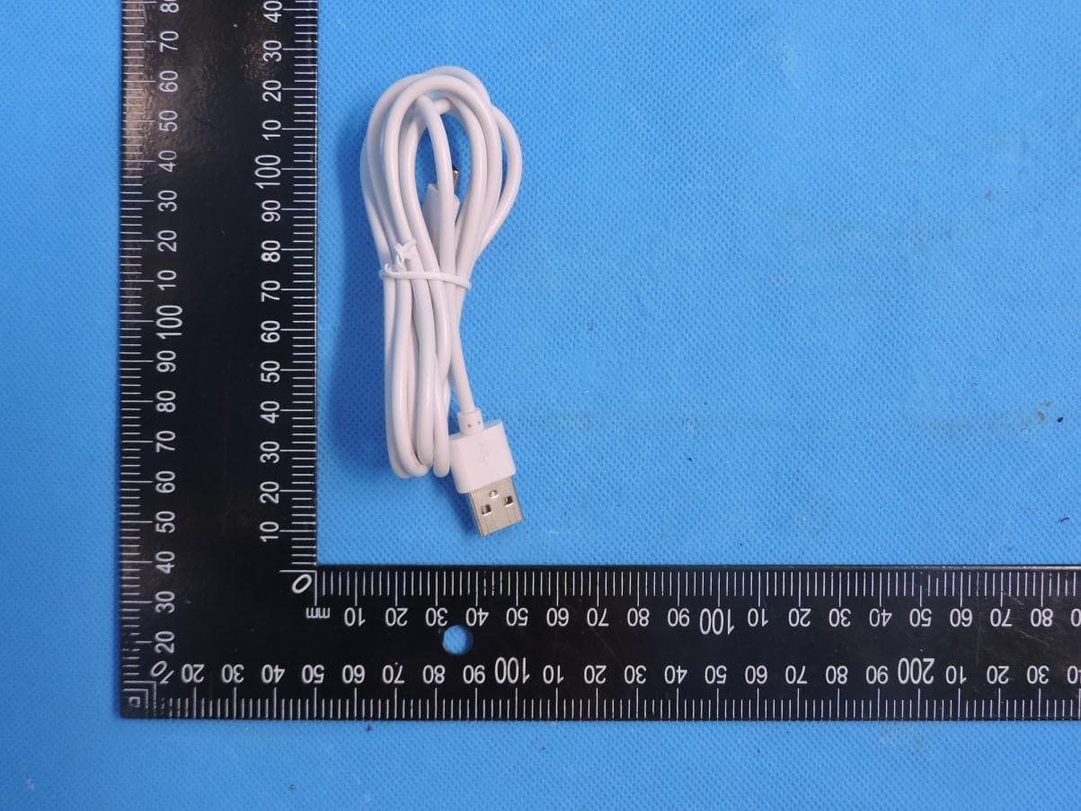
VMISE2KPT
Aug 11, 2024EVO 2K Indoor Pan Tilt Camera
Equipment Class
DTS - Digital Transmission System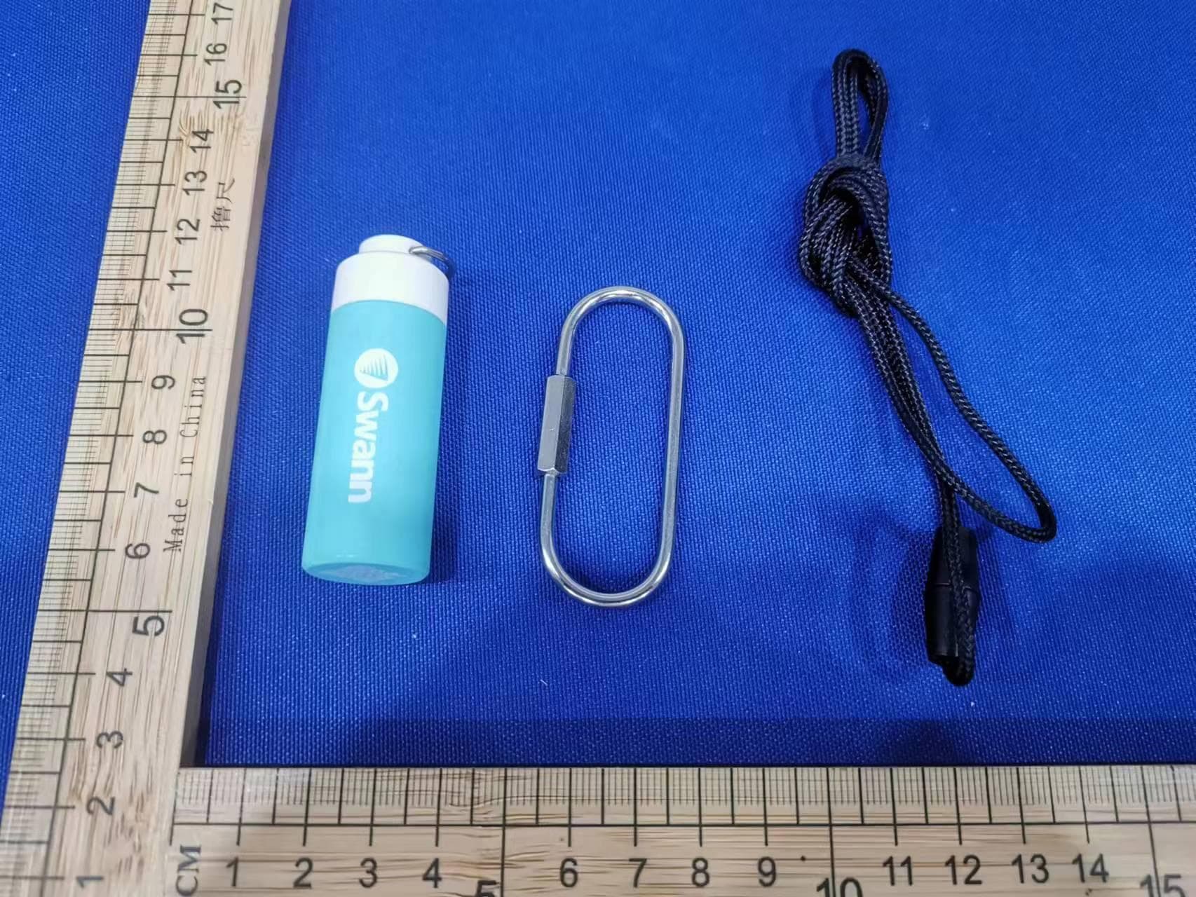
VMIMPRS
Sep 04, 2023Personal Alarm
Equipment Class
DTS - Digital Transmission System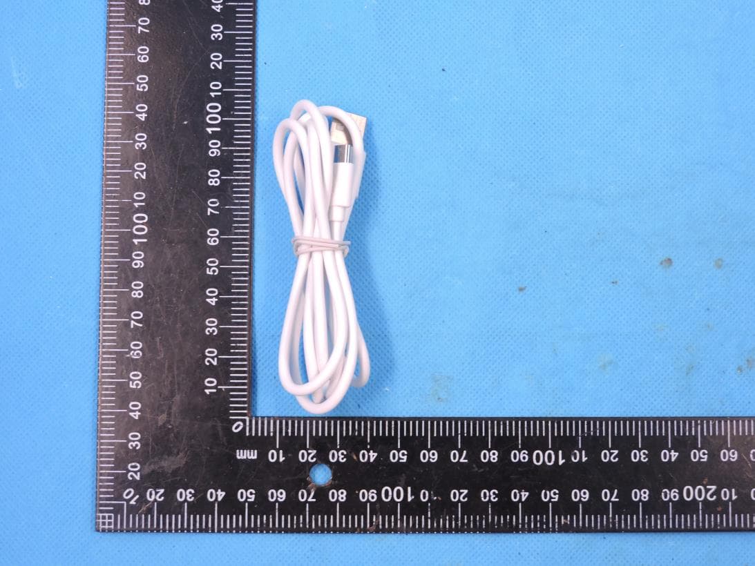
VMICOREPRO
Nov 07, 2022CoreCam Pro 2K Wire-Free Security Camera with Spotlight
Equipment Class
DTS - Digital Transmission System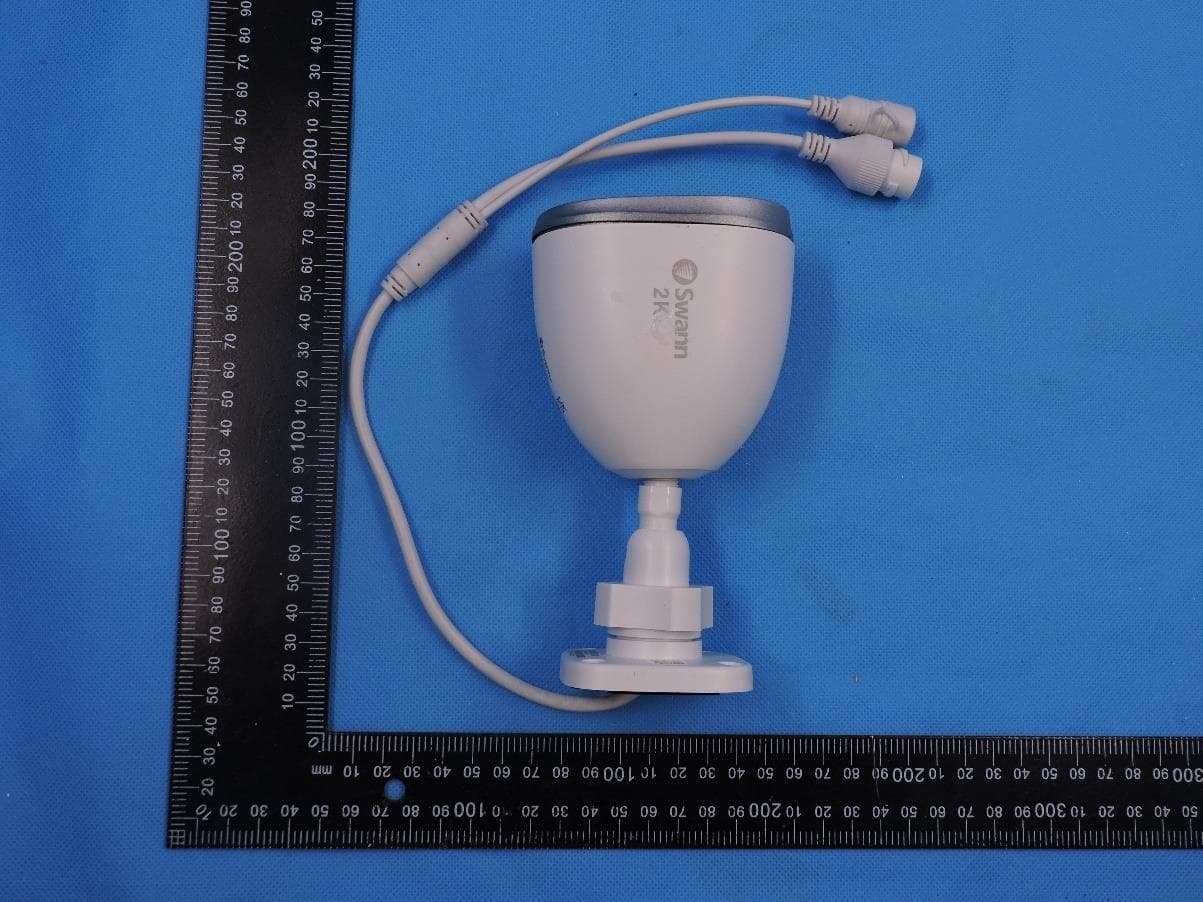
VMI2KOCAM
Aug 03, 20222K Outdoor Wi-Fi Spotlight Camera
Equipment Class
DTS - Digital Transmission System