VMTZBA-BT44Bluetooth module
ZBA, Inc.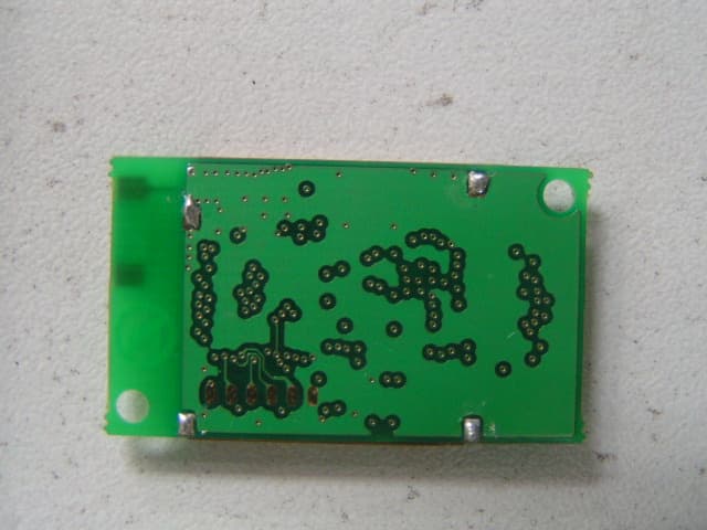
Click to zoom
Application Details
- Equipment Class
- DSS - Part 15 Spread Spectrum Transmitter
- Date of Grant
- Oct 30, 2007
- Application Purpose
- Original Equipment
- Date of Application
- Oct 30, 2007
- Equipment Note
- Bluetooth module
- Frequency Range
- 2402.00000000 - 2480.00000000
- Company
- ZBA, Inc.
- Country
- United States
Documents & Files
Document Text
Text extracted from the exhibit documents filed with the FCC. Open a document above to read the original.
Users Manual
ZBA, Inc. ZBA Bluetooth 2.0 Module with on board antenna. Assembly No. BC04-191 ZBA, Inc 94 Old Camplain Road, Hillsborough, NJ 08844 www.zbausa.com ZBA, Inc. "Changes or modifications not expressly approved by the party responsible for compliance could void the user's authority to operate the equipment." "This device complies with Part 15 of the FCC rules. Operations is subject to the following two conditions: (1) This device may not cause harmful interference, and (2) This device must accept any interference received, including interference that may cause undesired operation." "This equipment complies with FCC radiation exposure limits set forth for an unctrolled environment. End users must follow the specific operating instructions for satisfying RF exposure compliance. To maintain compliance with FCC RF exposure compliance requirements, please follow operation instruction as documented in this manual. " "The final end product must be labeled in a visible area with the following: Contains FCC ID: VMTZBA-BT44." "The end user manual shall include all required regulatory information/warning as show in this manual." Table of Contents ZBA, Inc. 1 Document Status .............................................................................................................. 4 2 Scope................................................................................................................................ 5 3 Bluetooth Assembly Description: .................................................................................... 5 4 Features ............................................................................................................................ 5 5 Applications ..................................................................................................................... 6 6 Block Diagram ................................................................................................................. 6 7 Specifications ................................................................................................................... 7 7.1 Pin Configurations & Dimensions ........................................................................... 7 7.2 Dimensional drawing ............................................................................................... 9 7.3 General Specifications ........................................................................................... 10 7.4 Electrical Characteristics ....................................................................................... 10 7.4.1 Absolute Maximum Ratings .......................................................................... 10 7.4.2 Radio Characteristics ..................................................................................... 10 7.4.3 Power Consumption....................................................................................... 13 7.4.3.1 Current measurements on the BC04-191 ................................................ 13 7.4.3.2 Datasheet specification of the BC04 External Module .............................. 13 8 Serial Port Profile........................................................................................................... 14 8.1 Default Configuration ............................................................................................ 14 8.2 Configuration Command Set-up & Procedures ..................................................... 14 8.2.1 Entering the Set-up Mode .............................................................................. 15 8.2.2 Testing the Communication Link .................................................................. 15 8.2.3 Command list ................................................................................................. 15 8.2.4 Set RS232 Baud Rate (bps)............................................................................ 15 8.2.5 Set/inquired UART Parameters ..................................................................... 16 8.2.6 Set Authentication.......................................................................................... 16 8.2.7 Set Password .................................................................................................. 16 8.2.8 Set Device Name............................................................................................ 17 8.2.9 Set Device Type ............................................................................................. 17 8.2.10 Set Master/Slave Mode .................................................................................. 17 8.2.11 Clear Paired Device Address ......................................................................... 18 8.2.12 Set Sniff Power Saving Mode........................................................................ 18 8.2.13 Set Sniff Power Saving Mode—Extended..................................................... 18 8.2.14 Reset to Factory Default ................................................................................ 18 8.2.15 Set/Inquire Scan Time.................................................................................... 18 8.2.16 Set/Inquire Paired Device .............................................................................. 19 8.2.17 Inquire Version .............................................................................................. 19 8.2.18 Inquired remote device Address ................................................................... 19 8.2.19 Set/Inquired Paired Device Address .............................................................. 20 8.2.20 Inquired Device BD Address ......................................................................... 20 8.2.21 Software Reset ............................................................................................... 20 8.2.22 Set/Inquire about Low power mode............................................................... 20 8.2.23 Set/ Inquire about Data processing mode …
Text truncated - open the document above for the full version.
Cover Letter(s)
Date: September 18, 2007 To: Federal Communications Commission, Authorization & Evaluation Division, 7435 Oakland Mills Road, Columbia, MD 21046 EMC Compliance Management Group 684 West Maude Avenue Sunnyvale CA 94085 Re: Confidentiality Request Gentlemen: This letter is to comply with 47 CFR 0.457(d)(2) pertaining to confidentiality material. ZBA Inc. requests that the following documents regarding this submission for FCC ID: VMTZBA-BT44 be kept confidential: 1. Block Diagram – Block Diagram.pdf 2. Schematics – Schematics.pdf These exhibits contain technical information, therefore this information cannot be published, if this information were to be made public it could be used to the disadvantage of the applicant in the marketplace. Yours Sincerely, Victor Zazzu ZBA Inc. VP Engineer ZBA, Inc. 94 old Camplain Road Hillsborough, NJ 08844 Ph: 908-359-2070 Fax: 908-595-0909 Web: Http://www.zbausa.com
Cover Letter(s)
In order to obtain a modular transmitter approval, a cover letter requesting modular approval must be submitted and the numbered requirements identified below must be addressed in the application for equipment authorization. 1. The modular transmitter must have its own RF shielding. This is intended to ensure that the module does not have to rely upon the shielding provided by the device into which it is installed in order for all modular transmitter emissions to comply with Part 15 limits. It is also intended to prevent coupling between the RF circuitry of the module and any wires or circuits in the device into which the module is installed. Such coupling may result in non-compliant operation. Yes, it has its own RF shielding, please see the external and internal pictures. 2. The modular transmitter must have buffered modulation/data inputs (if such inputs are provided) to ensure that the module will comply with Part 15 requirements under conditions of excessive data rates or over-modulation. Yes, the module has buffered data input. 3. The modular transmitter must have its own power supply regulation. This is intended to ensure that the module will comply with Part 15 requirements regardless of the design of the power supplying circuitry in the device into which the module is installed. Yes, the Bluetooth chip BC417143B contains a internal regulator, when the input power is 3.3V±10%, it can works normally. 4. The modular transmitter must comply with the antenna requirements of Section 15.203 and 15.204(c). The antenna must either be permanently attached or employ a “unique” antenna coupler (at all connections between the module and the antenna, including the cable). Any antenna used with the module must be approved with the module, either at the time of initial authorization or through a Class II permissive change. The “professional installation” provision of Section 15.203 may not be applied to modules. Yes, the module uses ceramic antenna on the PCB. 5. The modular transmitter must be tested in a stand-alone configuration, i.e., the module must not be inside another device during testing. This is intended to demonstrate that the module is capable of complying with Part 15 emission limits regardless of the device into which it is eventually installed. Unless the transmitter module will be battery powered, it must comply with the AC line conducted requirements found in Section 15.207. AC or DC power lines and data input/output lines connected to the module must not contain ferrites, unless they will be marketed with the module (see Section 15.27(a)). The length of these lines shall be length typical of actual use or, if that length is unknown, at least 10 centimeters to insure that there is no coupling between the case of the module and supporting equipment. Any accessories, peripherals, or support equipment connected to the module during testing shall be unmodified or commercially available (see Section 15.31(i)). Yes, we used two test jigs and evaluated two OEM boards. The EUT (module) was tested is a stand alone configuration. 6. The modular transmitter must be labeled with its own FCC ID number, and, if the FCC ID is not visible when the module is installed inside another device, then the outside of the device into which the module is installed must also display a label referring to the enclosed module. This exterior label can use wording such as the following: “Contains Transmitter Module FCC ID: XYZMODEL1” or “Contains FCC ID: XYZMODEL1.” Any similar wording that expresses the same meaning may be used. The Grantee may either provide such a label, an example of which must be included in the application for equipment authorization, or, must provide adequate instructions along with the module which explain this requirement. In the latter case, a copy of these instructions must be included in the application for equipment authorization. The module has its own FCC ID, And also in the Users Manual, there are instructions give to the OEM on how to label the end product. 7. The modular transmitter must comply with any specific rule or operating requirements applicable to the transmitter and the manufacturer must provide adequate instructions along with the module to explain any such requirements. A copy of these instructions must be included in the application for equipment authorization. For example, there are very strict operational and timing requirements that must be met before a transmitter is authorized for operation under Section 15.231. For instance, data transmission is prohibited, except for operation under Section 15.231(e), in which case there are separate field strength level and timing requirements. Compliance with these requirements must be assured. Yes, The EUT is compliant with all applicable FCC rules. 8. The modular transmitter must comply with any applicable RF exposure requirements. For example, FCC Rules in Sections 2.1091, 2.1093 and specific Sections of Part 15, including 15.319(i), 15.407(f), 15.253(f) and 15.255(g), require that Unlicensed PCS, UNII and millimeter wave devices perform routine environmental evaluation for RF Exposure to demonstrate compliance. In addition, spread spectrum transmitters operating under Section 15.247 are required to address RF Exposure compliance in accordance with Section 15.247(b)(4). Modular transmitters approved under other Sections of Part 15, when necessary, may also need to address certain RF Exposure concerns, typically by providing specific installation and operating instructions for users, installers and other interested parties to ensure compliance. The EUT is compliant with all applicable RF exposure requirements. See the RF exposure test in the report.
External Photos
Front View Rear View
ID Label/Location Info
Label Location
Internal Photos
Uncovered View Front View Rear View
Operational Description
Operation description: The BC04-191 is a general purpose Bluetooth module incorporating ceramic antenna designed to be incorporated into an end product. The BC04-191 Bluetooth Module is a Class 2 Bluetooth module using BlueCore4-External chipset from Cambridge Silicon Radio, a leading Bluetooth chipset supplier. It provides a fully compliant Bluetooth system for data and voice communications. Interfaces with a host via UART (USB optional). The module and device firmware is fully compliant with the Bluetooth specification V2.0. The module (BC04-191) is powered 3.3V from the OEM board. It has 79 channels and hopping in normal use. Specifications: • Default UART Baud Rate: 9600 baud • Number of Bits: 8 • Stop bit: One • Parity: None • H/W Flow Control: Disable • PIN: 1111 • Device Name: ZBA-SPP • Mode: Slave • Sleep Mode: Deep sleep when ever possible. • Partner pairing is dropped at power off or un-pairing by master. Please see the users manual for more detail information.
Test Report
684 West Maude Avenue Sunnyvale, CA 94085 Tel. (650) 988-0900 Fax (650) 988-6647 www.ecmg-global.com FCC CERTIFICATION RADIO MEASUREMENT TECHNICAL REPORT On Model Name: Bluetooth Module Model Number: BC04-191 Trademark : ZBA FCC ID : VMTZBA-BT44 Prepared for ZBA, Inc. According to FCC Part 15 (2007), Subpart C Test Report #: ZBA-0708-0717SH-FCC Prepared by: Chris Huang Reviewed by: Harry Zhao QC Manager: Paul Chen Test Report Released by: 2007, October 23 ⎯⎯⎯⎯⎯⎯⎯⎯⎯ ⎯⎯⎯⎯⎯⎯ Paul Chen Date NVLAP Lab code: 200068-0 ISO/IEC 17025:1999, ISO 9002:1994 Test Location Tests performed in a Certified ANSI Semi-Anechoic Chamber and Shielded Room performed testing. Test Site Location: CEMCL EMC Laboratory (Changzhou) No.18, Changzhou Qianjia Industry Park Yaoguan, Changzhou, Jiangsu, China 213011 Tel: 86-519-8776088 Fax: 86-519-8770888 FCC Registration Number: 174996 Accreditation Bodies The report is prepared by EMC Compliance Management Group, which is a fully accredited Test Laboratory for ITE, ISM and Telecommunications Products. Table of Contents DISCLAIMER NOTICE _________________________________________ 1 REPRODUCTION CLAUSE_____________________________________ 1 OPINIONS AND INTERPRETATIONS ___________________________ 1 STATEMENT OF MEASUREMENT UNCERTAINTY ______________ 1 ADMINISTRATIVE DATA _____________________________________ 2 EUT DESCRIPTION ___________________________________________ 2 ANTENNA STATEMENT ______________________________________ 2 TEST SUMMARY _____________________________________________ 3 TEST MODE JUSTIFICATION _________________________________ 4 EUT EXERCISE SOFTWARE ___________________________________ 4 EQUIPMENT MODIFICATION _________________________________ 4 TEST SYSTEM DETAILS ______________________________________ 5 CONFIGURATION OF TESTED SYSTEM________________________ 6 ATTACHMENT 1 – RADIATED SPURIOUS EMISSIONS __________ 7 ATTACHMENT 2 – RF EXPOSURE CALCULATION _____________ 22 ATTACHMENT 3 – CONDUCTED EMISSION TEST RESULTS ___ 24 ATTACHMENT 4 – BANDWIDTH _____________________________ 28 ATTACHMENT 5 – MAXIMUM PEAK OUTPUT POWER TEST___ 32 ATTACHMENT 6 – BAND EDGE TEST ________________________ 36 ATTACHMENT 7 – NUMBER OF HOPPING CHANNELS ________ 41 ATTACHMENT 8 – HOPPING CHANNELS SEPARATION _______ 44 ATTACHMENT 9 – TIME OF OCCUPYING TEST ____________ 48-55 EMC Test Report #: ZBA-0708-0717SH-FCC Prepared for ZBA, Inc. Prepared by EMC Compliance Management Group Page 1 of 55 Disclaimer Notice When government drawing, specification, or other data are used for any purpose other than in connection with a definitely related government procurement operation, the United States Government thereby incurs no responsibility nor any obligation whatsoever; and the fact that the Government may have formulated, furnished, or in any way supplied the said drawing, specifications, or other data, is not to be regarded by implication or otherwise in any manner licensing the holder or any other person or corporation, or conveying any rights or permission to manufacture, use, or sell patented invention that may in any way be related thereto. This report must not be used to claim product endorsement by NVLAP or any agency of the U.S. Government. Reproduction Clause Any reproduction of this document must be done in full. No single part of this document may be reproduced without permission from EMC Compliance Management Group, 684 West Maude Avenue Sunnyvale, CA 94085. Opinions and Interpretations This test report relates to the abovementioned equipment under test (EUT). Without the permission of EMC Compliance Management Group Test Lab this test report is not permitted to be duplicated in extracts. This test report does not entitle to carry any test mark on this or similar products. The manufacturer has sole responsibility of continued compliance of the device. Statement of Measurement Uncertainty The data and results referenced in the document are true and accurate. The reader is cautioned that there may be errors within the calibration limits of the equipment and facilities that can account for a nominal measurement error. Furthermore, component and process variability of devices similar to that tested may result in additional deviation. EMC Test Report #: ZBA-0708-0717SH-FCC Prepared for ZBA, Inc. Prepared by EMC Compliance Management Group Page 2 of 55 Administrative Data Test Sample : Bluetooth Module Model Number : BC04-191 Trade Mark : ZBA Date Tested : 2007, August 31 / 2007, September 18 / 2007, October 18 Applicant : ZBA, Inc. 94 old camplain Rd Hillsborough NJ 08844 Telephone : 908-359-2070 Manufacturer : Chongqing Jinou Science and Technology Development Co., Ltd. Guigu City Villa 12-2-101, huanxuan branch 108# Yuzhou Road, Hi-tech Development zone, Chongqing 400041, P.R.China Telephone : 86-23-68798999 Fax : 86-23-68889515 EUT Description ZBA, Inc. Model number BC04-191(referred to as the EUT in this test report) is a Bluetooth Module. We tested the EUT with two kinds of test jigs: One of the test jig named: JO-0205-1-1, uses USB port to power and communicate. The other test jig named: JO-0208-1-5, uses USB port to power and RS232 port to communicate. And, for the test jigs, the data and power connector is a little different. Both of the two kinds of test jigs are tested. For RF test items, only one was recorded. Antenna Statement The Bluetooth module has no antenna connector. It has it’s integrate PCB antenna. EMC Test Report #: ZBA-0708-0717SH-FCC Prepared for ZBA, Inc. Prepared by EMC Compliance Management Group Page 3 of 55 Test Summary The Electromagnetic Compatibility requirements on BC04-191 for this test are stated below. All results listed in this report relate exclusively to this above-mentioned model as the Equipment Under Test. This report confers no approval or endorsement upon any other component, host or subsystem used in the test set-up. EMC Test Items Reference FCC Part 15 (2007), Subpart C Specification Description Test Results Remark FCC Part 15.203 An…
Text truncated - open the document above for the full version.
Test Setup Photos
Conduction Test Setup Pictures Radiation Test Setup Pictures (Low Frequency) Radiation Test Setup Pictures (High Frequency) Test Configration Setup with test jig #1 Front View Rear View Setup with test jig #2 Front View Rear View
Contact Information
Applicant
Vivian Han
Test Firm
CEMCL EMC Laboratory (Changzhou)Xiaoming Lu
Technical Specifications
| # | Rule Parts | Frequency Range | Power Output |
|---|---|---|---|
| 1 | 15C | 2.40 GHz - 2.48 GHz | 2.57 mW |
Other Applications from ZBA, Inc.
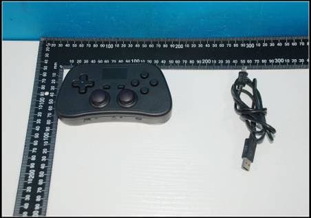
VMT-ZBAGC0-KG
Nov 04, 2012WIRELESS HID CONTROLLER
Equipment Class
DSS - Part 15 Spread Spectrum Transmitter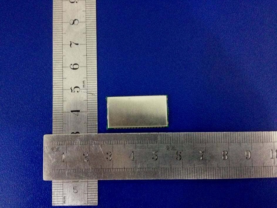
VMTBT44-111S
Jul 17, 2012Class 1 Bluetooth Module
Equipment Class
DSS - Part 15 Spread Spectrum Transmitter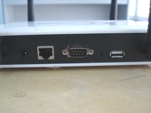
VMTBTMS-X
Jun 14, 2010Bluetooth Media System
Equipment Class
DSS - Part 15 Spread Spectrum Transmitter