VNH-T001MHDMI Dongle
Inkel Corporation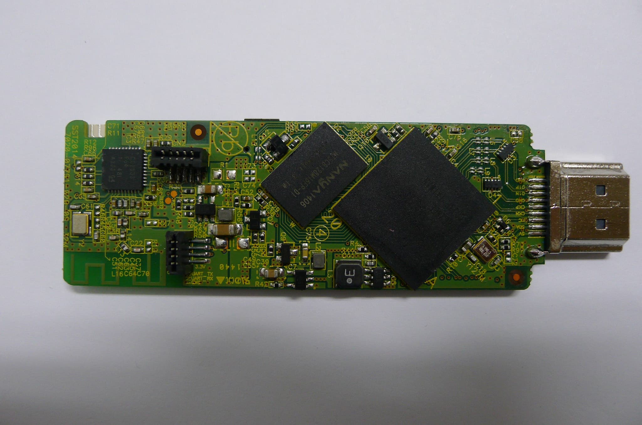
Click to zoom
Application Details
- Equipment Class
- DTS - Digital Transmission System
- Date of Grant
- Nov 03, 2014
- Application Purpose
- Original Equipment
- Date of Application
- Nov 03, 2014
- Equipment Note
- HDMI Dongle
- Frequency Range
- 2405.00000000 - 2480.00000000
- Company
- Inkel Corporation
- Country
- South Korea
Documents & Files
Document Text
Text extracted from the exhibit documents filed with the FCC. Open a document above to read the original.
Users Manual
User plugs the device in, device loads. Model name: VUDU SPARK (HDMI Dongle) RS ‐ T1 (Remote controller) CC 00 F CC ID: VNH ‐ T 00 1M VNH ‐ T001R Load Screen (video) 1 Device searches for wifi. 2 Device displays available wifi choices. User then selects p referred wifi. p 3 User enters wifi password. 4 User enters wifi password. 5 User can choose to show password. 6 After completing password, users submits password. 7 Device connect to the chosen wifi. 8 If the connection is not successful, user is notified. Failure to connect reverts user back to wifi selection screen (Slide #3). Failure to connect reverts user back to wifi selection screen (Slide #3). 9 On first ‐ time boot, user will be prompted to create a Vudu account or login. Landing screen TBD. 10 After creating a Vudu account or logging in, user will access full Vudu app. 11 FCC Notice This equipment has been tested and found to comply with the limits for a Class B digital device, pursuant topart 15 of the FCC Rules. These limits are designed to provide reasonable protection against harmful interferencein a residential installation. This equipment generates, uses and can radiate radio frequency energy and, if not installed and used in accordanc e with the instructions, may cause harmful interference to radio communications. However, there is no guarantee that interference will not occur in a particular installation. If this equipment does cause harmful interference to radio or television reception, which can be determined by turning the equipment off and on, the user is encouraged to try toc orrect the interference by one or more of the following measures: - Reorient or relocate the receiving antenna.- Increase the separation between the equipment and receiver.- Connect the equipment into an outlet on a circuit different from that to which the receiver is connected.- Consult the dealer or an experienced radio/TV technician for help.This device complies with part 15 of the FCC Rules. Operation is subject to the following two conditions: (1) This device may not cause harmful interference, and (2) this device must accept any interference received, including interference that may cause undesired operation. IMPORTANT NOTE: FCC RF Radiation Exposure Statement: This equipment complies with FCC RF radiation exposure limits set forth for an uncontrolled environment. This equipment should be installed and operated with a minimum distance of 20 centimeters between the radiator and your body. This transmitter must not be co-located or operating in conjunction with any other antenna or transmitter. NOTE: THE GRANTEE IS NOT RESPONSIBLE FOR ANY CHANGES OR MODIFICATIONS NOT EXPRESSLY APPROVED BY THE PARTY RESPONSIBLE FOR COMPLIANCE. SUCH MODIFICATIONS COULD VOID THE USER’S AUTHORITY TO OPERATE THE EQUIPMENT. (FCC Part 15.21) Caution: changes or modifications not expressly approved by the party responsible for compliancecould void the user's authority to operate the equipment. z Only batteries of the same or equivalent type as recommended are to be used. z Insert batteries with the correct polarity as indicated on the product. z Remove batteries during long periods of non-use. Remove exhausted batteries promptly. z This product requires two AAA(UM-4) batteries z Dispose of batteries safety, Batteries may explode or leak if disposed of in a fire. z Protect the enviroment by not disposing of the batteries or this product with houhold waste (2002/96/EC) Check you local authority for recycling advice and facilities KEEP PACKING FOR FUTURE REFERENCE. MADE IN KOREA
Cover Letter(s)
Inkel Corporation. 93, Cheongjung-Ro, Bupyeong-Gu, Incheon, 403-853, Republic of Korea Date: October 27, 2014 Federal Communications Commission 7435 Oakland Mills Road Columbia MD 21046 c.c. Timco Engineering, Inc. Certification Division 849 N.W. State Road 45 P.O. Box 370 Newberry, Florida 32669 USA To whom it may concern: I, the undersigned, hereby authorize Technical Manager Issac Jin of MOVON CORPORATION and here after referred to as MOVON CORPORATION , to act on our behalf in all manners relating to application for equipment authorization, including signing of all documents relating to these m atters. Any and all acts carried out by Technical Manager Issac Jin of MOVON CORPORATION on our behalf shall have the same effect as acts of our own. I, the undersigned, hereby certify that we are not subject to a denial of federal benefits, that includes FCC benefits, pursuant to Section 5301 of the Anti-Drug Abuse Act of 1988, 21 U.S.C. 853(a). In authorizing MOVON CORPORATION as our agent, we still recognize that we are responsible to: a) comply with the relevant provisions of the certification program; b) make all necessary arrangements for the conduct of the evaluation, including provision for examining documentation and access to all areas, records (including internal audit reports) and personnel for the purposes of evaluation (e.g. testing, inspection, assessment, surveillance, reassessment) and resolution of complaints; c) make claims regarding certification only in respect of the scope for which certification has been granted; d) do not use our product certification in such a manner as to bring the Certification Division into disrepute and not make any statement regarding our product certification which the Certification Division may consider misleading or unauthorized; Inkel Corporation. 93, Cheongjung-Ro, Bupyeong-Gu, Incheon, 403-853, Republic of Korea e) upon suspension or cancellation of certification, discontinue use of all advertising matter that contains any reference thereto and return any certification documents as required by the Certification Division; f) use certification only to indicate the products are certified as being in conformity with specified standards; g) endeavor to ensure that no certificate or report nor any part thereof is used in a misleading manner; h) ensure that any reference to our product certification in communication media such as documents, brochures or advertising, complies with the requirements of the Certification Division; i) keep a record of all complaints made known to the us relating to the product’s compliance with requirements of the relevant standard and to make these records available to the Certification Division when requested; j) take appropriate action with respect to such complaints and any deficiencies found in products or services that affect compliance with the requirements for certification; k) document the actions taken. This authorization is valid until further written notice from the applicant. Sincerely Yours, Eun-HWan, Shim / R&D Strategy Team Principal Research Engineer Inkel Corporation. REMARK: 1. This authorization letter will be sent along with your application when filing with the Certification Division. 2. Please follow the format and type it on company letterhead and send original to us. 3. Authorized signature must be in agreement with grantee code contact in FCC database.
Cover Letter(s)
October 22, 2014 Federal Communications Commission 7435 Oakland Mills Road Columbia MD 21046 Subject: Request for Confidentiality FCC ID: A3LSMG7508 W To Whom It May Concern: Pursuant to the provisions of Sections 0.457 and 0.459 of the Commission’s rules (47 CFR §§ 0.457, 0.459), we are requesting the Commission to withhold the following attachments as confidential document from public disclosure indefinitely. Schematics Block Diagram Operational Description Antenna Specification Parts List Tune-Up Procedure Above mentioned document contains detailed system and equipment description are considered as proprietary information in operation of the equipment. The public disclosure of above documents might be harmful to our company and would give competitor an unfair advantage in the market. In additional to above mentioned documents, pursuant to Public Notice DA 04-1705 of the Commission’s policy, in order to comply with the marketing regulations in 47 CFR §2.803 and the importation rules in 47 CFR §2.1204, while ensuring that business sensitive information remains confidential until the actual marketing of newly authorized devices. We are requesting the commission to grant short-term confidentiality request on the following attachments until 180 days External Photos Internal Photos Test Setup Photos User Manual It is our understanding that all measurement test reports, FCC ID label format and correspondence during certification review process cannot be granted as confidential documents and such information will be available for public review once the grant of equipment authorization is issued. Best Regards CHANHO, YOUN General Manager Samsung Electronics CO. LTD TEL: +1-973-808-6362 E-mail: [email protected]
External Photos
External photos of EUT Front view of EUT Rear view of EUT Side view of EUT Side view of EUT Side view of EUT Side view of EUT
ID Label/Location Info
MODEL : VUDU SPARK FCC ID : VNH-T001M Made in Korea 5 V0.5 A
Internal Photos
Internal photos of EUT Internal photo (Front) Internal photo (Rear) Internal photo (Front) WLAN Module (removed shield case) Antenna (Zigbee) Antenna(WLAN)
Operational Description
ACS2450HFL57 Ver 1.0 (2014.10.08) 1/7 FCC Approval Sheet Products Dielectric Chip Antenna Customer Inkel Model HDMI Dongle Supplier PARTRON Supplier CODE ACS2450HFL57 SAMSUNG By designed By checked By approved / / / PARTRON By designed By checked By approved 김홍기 Antenna 2 Team Quality Assurance Laboratory Hongki.Kim Nam-Sik. Min Byoung-Jun.Yim 10/08 10/08 10/08 2014. 10.08 22-6, Seokwoo-dong, Hwaseong-si, Gyeonggi-doKorea, 440-170Tel : 82-31-201-7870~6Fax : 82-31-201-7800www.partron.co.kr ACS2450HFL57 Ver 1.0 (2014.10.08) 2/7 - Contents - ※ Cover ............................ .................................... .............................. ............................ ......................... 1p ※ Contents ............................ .................................... .............................. ......................... ......................... 2p 1. Antenna specification ....................... .............................. .............................. ...................... ................... 3p 2. Structure .......................................... .............................. ........................ .................... ............................ 7p . ACS2450HFL57 Ver 1.0 (2014.10.08) 3/7 1. Antenna specification Specification VSWR Dielectric Chip Ant. Monopole Type Ant. 0dBi Nondirectional Cross Polarization Internal Antenna PARTRON / HDMI Dongle ACS2450HFL57 Ver 1.0 (2014.10.08) 4/7 [ Azimuth ] Gain Radiation Pattern A z i m u t h Frequency Max. Avg. 2400 -1.46 -4.24 2425 -1.87 -4.86 2445 -0.84 -3.89 2465 -2.36 -5.52 2485 -2.11 -5.56 ACS2450HFL57 Ver 1.0 (2014.10.08) 5/7 [ Elevation1 ] Gain Radiation Pattern E l eva t i on 1 Frequency Max. Avg. 2400 0.06 -6.26 2425 -0.46 -6.90 2445 0.64 -5.81 2465 -0.81 -7.31 2485 -0.82 -7.27 ACS2450HFL57 Ver 1.0 (2014.10.08) 6/7 [ Elevation2 ] Gain Radiation Pattern E l eva t i on 2 Frequency Max. Avg. 2400 -0.58 -6.04 2425 -0.82 -6.48 2445 0.40 -5.29 2465 -0.83 -6.53 2485 -0.43 -6.20 ACS2450HFL57 Ver 1.0 (2014.10.08) 7/7 2. Structure Antenna Pattern Side2 Top Bottom Side1 Application Note AN043 4 ANTENNA DESIGN The PCB antenna on the CC2511 USB dongle reference design is a meandered Inverted F Antenna (IFA). The IFA was designed to match an impedance of 50 ohm at 2.45 GHz. Thus no additional matching components are necessary. 4.1 Design Goals The reflection at the feed point of the antenna determines how much of the applied power is delivered to the antenna. A reflection of less than -10 dB across the 2.4 GHz ISM band, when connected to a 50 ohm source, was a design goal. Reflection of less than -10 dB, or VSWR less than 2, ensures that more than 90% of the available power is delivered to the antenna. Bandwidth is in this document defined as the frequency band where more than 90% of the available power is delivered to the antenna. Another design goal was to fit the size of the PCB antenna on a USB dongle and to obtain good performance also when the dongle is connected to a computer. 4.2 Simulation IE3D from Zeland, which is an electromagnetic simulation tool, was used to design the antenna. The accuracy of the simulation is controlled by the mesh. An increase of the mesh increases the simulation time. Thus, for initial simulations mesh = 1 should be used. When a fairly good result is achieved a higher mesh should be used to obtain more accurate results. Comparison of simulation and measurement results shows that the measured reflection is between the result obtained with mesh = 5 and mesh = 1; see Figure 2 for details. Figure 2: Comparison of Simulation and Measurements Results SWRA117D Page 3 of 21 Application Note AN043 4.3 Layout and Implementation Small changes of the antenna dimensions may have large impact on the performance. Therefore it is strongly recommended to make an exact copy of the reference design to achieve optimum performance. The easiest way to implement the antenna is to import the gerber or DXF file showing the antenna layout. These files are named IFA_USB.spl and IFA_USB.dxf respectively and are included in the CC2511 USB dongle reference design available from http://www.ti.com\lpw. The imported file can be used as a template when drawing the antenna. By using this procedure it should be possible to make an exact copy. If the PCB CAD tool being used does not support import of DXF or gerber files, Figure 3 and Table 1 should be used to ensure correct implementation. It is recommended to generate a gerber file for comparison with IFA_USB.spl when making a manual implementation. Most gerber viewers have the possibility to import several gerber files at the same time. Thus by placing the gerber file, showing the manually implemented antenna, on top of IFA_USB.spl it is easy to verify that the antenna is correctly implemented. It is also recommended to use the same thickness and type of PCB material as used in the reference design. Information about the PCB can be found in a separate readme file included in the reference design. To compensate for a thicker/thinner PCB the antenna could be made slightly shorter/longer. Figure 3: Antenna Dimensions L1 3.94 mm L2 2.70 mm L3 5.00 mm L4 2.64 mm L5 2.00 mm L6 4.90 mm W1 0.90 mm W2 0.50 mm D1 0.50 mm D2 0.30 mm D3 0.30 mm D4 0.50 mm D5 1.40mm D6 1.70 mm Table 1: Antenna Dimensions SWRA117D Page 4 of 21 Application Note AN043 5.2 Radiation Pattern The radiation pattern for the antenna implemented on the CC2511 USB dongle reference design has been measured in an anechoic chamber. Figure 7 through Figure 12 shows radiation patterns for three planes, XY, XZ and YZ, measured with vertical and horizontal polarization. All these measurement were performed without connecting the dongle to a computer. Figure 13 and Figure 14 shows the radiation pattern when the dongle is connected to a laptop. All measurements were performed with 0 dBm output power. Figure 6 shows how the different radiation patters are related to the positioning of the antenna. XY plane YZ plane XZ plane Fi…
Text truncated - open the document above for the full version.
Test Report
MOVON CORPORATION Report Number: MOV-14-RF-I057 Page : (1) of (90) The results shown in this test report refer only to the sample(s) tested unless otherwise stated. This test report cannot be reproduced, except in full, without the written approval of MOVON CORPORATION. FCC Part 15 Subpart C §15.247 Test Report Equipment Under Test HDMI Dongle Model Name VUDU SPARK Applicant Inkel Corporation. FCC ID VNH-T001M Manufacturer Inkel Corporation. Date of Test(s) 2014. 10. 15 ~ 2014. 10. 27 Date of Issue 2014. 10. 28 In the configuration tested, the EUT complied with the standards specified above. Issue to Issue by Inkel Corporation. 93, Cheongjung-ro, Bupyeong-Gu, Incheon, 403-853, Korea Tel.: +82-32-650-6141 Fax: +82-32-650-6466 MOVON CORPORATION 498-2, Geumeo-ro, Pogok-eup, Cheoin-gu, Yongin-si, Gyeonggi-do, Korea, 449-812 Tel.: +82-31-338-8837 Fax: +82-31-338-8847 MOVON CORPORATION Report Number: MOV-14-RF-I057 Page : (2) of (90) The results shown in this test report refer only to the sample(s) tested unless otherwise stated. This test report cannot be reproduced, except in full, without the written approval of MOVON CORPORATION. Revision history Revision Date of issue Description Revised by -- August 28, 2014 Initial -- MOVON CORPORATION Report Number: MOV-14-RF-I057 Page : (3) of (90) The results shown in this test report refer only to the sample(s) tested unless otherwise stated. This test report cannot be reproduced, except in full, without the written approval of MOVON CORPORATION. Table of contents 1. GENERAL INFORMATION ............................................................................................. 4 1.1. DETAILS OF APPLICANT .................................................................................................................................... 4 1.2. MANUFACTURER / FACTORY INFORMATION ........................................................................................................ 4 1.3. SUMMARY OF TEST RESULTS ............................................................................................................................ 5 2. EUT DESCRIPTION ........................................................................................................ 6 2.1. DECLARATIONS BY THE MANUFACTURER ............................................................................................................ 6 2.2. DETAILS OF MODIFICATION ............................................................................................................................... 6 3. MEASUREMENT EQUIPMENT ...................................................................................... 7 4. TRANSMITTER RADIATED SPURIOUS EMISSIONS AND CONDUCTED SPURIOUS EMISSIONS .................................................................................................................. 8 4.1. TEST SETUP ................................................................................................................................................... 8 4.1.1. TRANSMITTER RADIATED SPURIOUS EMISSIONS ............................................................................................... 8 4.2. LIMIT ............................................................................................................................................................. 9 4.3. TEST PROCEDURES ....................................................................................................................................... 11 4.3.1. TEST PROCEDURES FOR RADIATED SPURIOUS EMISSIONS ............................................................................... 11 4.3.2. TEST PROCEDURES FOR CONDUCTED SPURIOUS EMISSIONS ........................................................................... 11 4.4. TEST RESULT ............................................................................................................................................... 12 4.4.1. SPURIOUS RADIATED EMISSION ................................................................................................................... 12 4.4.4. BAND EDGE .............................................................................................................................................. 32 4.4.5. OUT OF BAND EMISSIONS IN NON-RESTRICTED FREQUENCY BAND ................................................................... 38 5. 6 ㏈ BANDWIDTH ....................................................................................................... 63 5.1.TEST SETUP .................................................................................................................................................. 63 6.2. LIMIT ........................................................................................................................................................... 63 6.3. TEST PROCEDURE ........................................................................................................................................ 63 6.4. TEST RESULTS ............................................................................................................................................. 63 6. MAXIMUM OUTPUT POWER MEASUREMENT .......................................................... 72 6.1. TEST SETUP. .............................................................................................................................................. 72 6.2. LIMIT ........................................................................................................................................................... 72 6.3 TEST PROCEDURE..................................................................................................................72 6.4 TEST RESULTS .............................................................................................................................................. 73 7. POWER SPECTRAL DENSITY MEASUREMENT ....................................................... 76 7.1. TEST SE…
Text truncated - open the document above for the full version.
Test Setup Photos
Test setup photo of EUT A. Setup photo of EUT Photo of radiated spurious emission at below 30 ㎒ Photo of radiated spurious emission at 30 ㎒ ~ 1 000 ㎒ Photo of radiated spurious emission at above 1 000 ㎒ Photo of Conducted emission at below 30 ㎒
Contact Information
Applicant
Eun-HWan Shim(R&D Strategy Team Principal Research Engineer)
Test Firm
MOVON CorporationDanny Kim
Technical Specifications
| # | Rule Parts | Frequency Range | Power Output |
|---|---|---|---|
| 3 | 15C | 2.40 GHz - 2.48 GHz | 380.00 µW |
Other Applications from Inkel Corporation

VNH-IK8ARS
Dec 03, 2015Bluetooth module
Equipment Class
DSS - Part 15 Spread Spectrum TransmitterVNH-T001R
Oct 28, 2014REMOTE CONTROLLER
Equipment Class
DTS - Digital Transmission System
VNH-IK-CSRBC05
Sep 22, 2014Bluetooth module
Equipment Class
DSS - Part 15 Spread Spectrum Transmitter
VNH-IK-CSR8645
Feb 17, 2014BLUETOOTH MODULE
Equipment Class
DSS - Part 15 Spread Spectrum Transmitter
VNH-S5
Aug 25, 2013SURROUND PANORAMA
Equipment Class
DSS - Part 15 Spread Spectrum Transmitter