VNK15554TRUST US DS-3250 MULTIMEDIA DESKSET-KEYBOARD
Trust International BV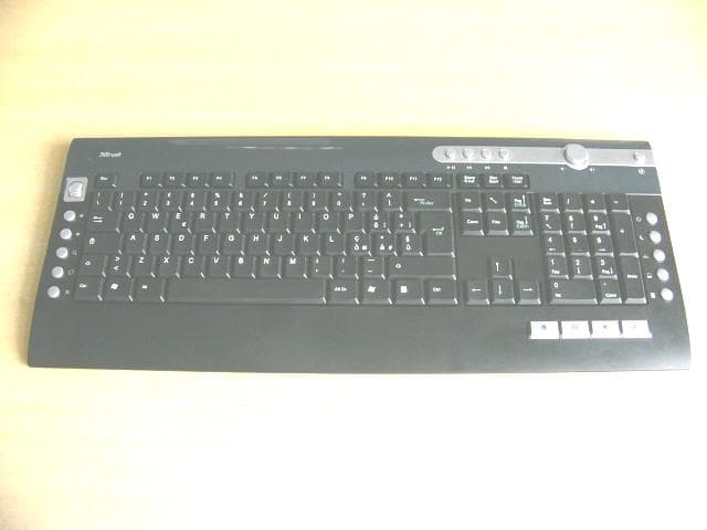
Click to zoom
Application Details
- Equipment Class
- DXX - Part 15 Low Power Communication Device Transmitter
- Date of Grant
- Sep 19, 2007
- Application Purpose
- Original Equipment
- Date of Application
- Sep 19, 2007
- Equipment Note
- TRUST US DS-3250 MULTIMEDIA DESKSET-KEYBOARD
- Frequency Range
- 27.14500000 - 27.14500000
- Company
- Trust International BV
- Country
- Netherlands
Documents & Files
Document Text
Text extracted from the exhibit documents filed with the FCC. Open a document above to read the original.
Users Manual
UK WIRELESS OPTICAL MULTIMEDIA DESKSET DS- 3250 DE FR IT ES PL NL PT GR DK SE HU CZ FI NO TR RU User’s manual Version 1.0 SK USER’S MANUAL Installation 1 2 A B C D E G F H 4 3 USER’S MANUAL USER’S 1 MANUAL Product information A: Internet Buttons Browser back Browser forward Search Browser reload Browser stop C: Launch/special Buttons Start Internet Browser Start E-mail program Favorites Launch Windows default Mediaplayer* Insert special characters D: System Buttons Power Sleep / Standby Wake up My computer* Calculator* B: Media Keys Play / Pause Previous track Next track Stop Volume down direction Volume up direction Mute Media Center Functions Previous Screen Channel Up Channel Down OK E: USB Receiver F: Mouse 4 th and 5 th buttons (Browser Back/ Forward ) G: Scrollwheel with on frontside Battery empty LED H: Multimedia buttons (functions: see table B) * Driver from Trust website needed to support function in Windows 2000 UK Installation 1 Open battery compartments on bottom sides of mouse and keyboard and place the 4 batteries. 2 Connect USB Transmitter to PC and wait until automatic installation has completed. (Answer any question Windows asks with Allow, Continue, Next, OK or Yes) 3 Push connect button on USB Transmitter. 4 Push connect button on bottom side of Keyboard and finally connect button on bottom side of mouse. USER’S MANUAL 2 Note Multimedia and Office keys • Launch keys will start the default internet browser, E-mail program and Mediaplayer installed on your PC. Configure default programs: XP: Start Æ Control PanelÆ Add/Remove Programs Æ Set Program Access and Defaults. Vista: Start Æ Control PanelÆDefault ProgramsÆSet programs access and computer defaultsÆ Custom • The multimedia keys also work with other media player software like Itunes. • 4th and 5 th Mouse button only work in games that support standard 5 button mice. Special characters • The keyboard country layout settings in Windows should correspond with the keyboard layout of your Trust keyboard. Layout of the Trust keyboard is specified by a sticker on the Box. To set the keyboard Layout in Windows: Go to: Start Æ Control Panel (classic view) Æ Regional and Language Options Æ Languages Æ Details (Vista: “Change Keyboards”) • The Alt Gr key gives access to special characters like the € sign. An overview of the special characters per country is available at www.trust.com/keyboardlayout. Performance • Maximum Wireless working distance is around 2,5 meter. • Reduced wireless performance can be caused by: - (Metal) objects close to or between transmitter and keyboard Æ Remove objects. - Other wireless devices close by Æ Remove devices or reconnect USB transmitter to get different communication ID. - Empty batteries Æ Replace batteries. • Mouse will have reduced tracking performance on very shiny or transparent surfaces. Energy • Battery lifetime: Mouse: +/- 130 hours. Keyboard: +/- 4500 hours. • The mouse will enter sleep mode after 10 minutes of inactivity, but will respond immediately after pressing a button. • When mouse batteries are empty, the battery empty LED in front of the scroll wheel will light. • Never recharge the batteries provided and never throw them onto a fire. • Observe local regulations when disposing of batteries. Safety instructions • Do not open or repair this device. • Do not use the device in a damp environment. Clean the device with a dry cloth. USER’S MANUAL 3 See www.trust.com/15052 for up-to-date FAQs, Windows 2000 driver and instruction manuals. For extensive service, register at www.trust.com/register. UK • This device meets the essential requirements and other relevant conditions of the applicable European directives. The Declaration of Conformity (DoC) is available at www.trust.com/15052/ce. Wireless • This class 1 wireless device works at a frequency of 27 MHz It meets the essential requirements and other relevant conditions of R&TTE Directive 1999/5/EC and can be used in the following countries: all EU countries, as well as RU, TR, NO and HU. There are no limitations per channel for the above- mentioned countries. See www.trust.com/15052 for an updated list of the countries where the use of this device is permitted. • There may be restrictions for the use of this device outside of the EU. If this device is used outside of the EU, check whether this device meets the local regulations. Frequency: 27.045 ~ 27.145MHz Bandwidth: approx. 6 KHz; Power: 0,5 mW. • Be careful when using wireless devices if you have a pacemaker or are dependent on other life- saving, sensitive electronic equipment, because this device transmits radio signals. • If possible, dispose of the device at a recycling centre. Do not dispose of the device with the household waste. Warranty & copyright • This device has a two-year product warranty which is valid from the date of purchase. See www.trust.com/warranty for more information. • It is forbidden to reproduce any part of this instruction manual without the permission of Trust International B.V.
External Photos
EUT top view EUT bottom view
ID Label/Location Info
This device complies with Part 15 of the FCC Rules. Operation is subject to the following two conditions: (1) this device may not cause harmful interference, and (2) this device must accept any interference received, including interference that may cause undesired operation. Proposed Label Location on EUT EUT Bottom View/Proposed FCC ID Label Location FCC ID: VNK15554
Internal Photos
EUT inside whole view Main board component side Main board solder side
Schematics
55 44 33 22 11 D D C C B B A A C18 C17 C16 C15 C14 C13 C12 C11 C10 C9 C8 C7 C6 C5 C4 C3 C2C1 R8R7R6 R5R4R3R2R1 V1V2Z1Z2 V1V2Z1Z2 R8R7R6R5R4R3R2R1C18C17C16C15C14C13C12C11C10C9C8C7C6C1C2C3C4C5 0 0 0000 0 0 0 BAT VDD VDD BAT 0 0 0 0 VDD VDD VDD C3 *27p C133p XT132.768KHz SW2 R9 100k C15104 C2 33p C7B *30p + C10200UF R8200k C13104 L1 100uH C7A *24p R50 C5*56p + C14200UF L3 *0uH R710 BT1 SW1 C12104 C8 *3p C4*12p R3 1.5M + C11 200UF R1 4.7M J1CON261234567891011121314151617181920212223242526 D15819 C622p R2 470 R4 470k MA6231 1234567 10111213141516 28 29 30 31 32 33363738394041434445464748 49 50 51 54 55 56 57 58 59 60 62 63 89 6417 18 19 20 21 22 23 24 25 26 27 343542 52 53 61 C1C0VDD1VDD5OSC-INOSC-OUT10TXCBORF-INORF-OUTRF-OUTORF-IN2TXD SVDIN VSS1 R7 R6 R5 R4R1R0 38394041 RFSEL VSS VL DCVR C19C18 C17 C16 C15 C12 C11 C10 C9 C8 C7 C6 C4 C3 89 C2BTL COL21 COL20 V1 V2 Z1 Z2 24 W1 W2 XTB R3R2 42 C14 C13 C5 C9*75p XT2A 27.095MHz SWE L2 1.8uH XT2B 27.145MHz D2
Test Report
The test report consists 18 pages in total. It may be duplicated completely for legal use with the allowance of the applicant. It shall not be reproduced except in full, without the written approval of Ke Mei Ou Laboratory Corporation. The test result in the report only applied to the tested sample. FCC TEST REPORT Under FCC 15 Subpart C, Paragraph 15.227 Prepared For: Trust International BV Laan van Barcelona 600, 3317 DD Dordrecht, Postbus 8043, 3301 CA Dordrecht, The Netherlands September 20, 2007 FCC ID: VNK15554 EUT: TRUST US DS-3250 WIR MM DESKST-KEYBOARD Model: 15554 Report Type: Original Report Test Engineer: Jacky Huang Test Date: September 18, 2007 Review By: Apollo Liu / Manager Ke Mei Ou Laboratory Co., Ltd. 7A, Jiaxiangge, Jiahuixincheng, No.3027, Shennan Rd., Futian, Shenzhen, Guangdong, P.R.China. Zip Code: 518033 Tel: + 86 755 83642690 Fax: + 86 755 83297077 www.kmolab.com Trust International BV FCC ID: VNK15554 KMO FCC ID Report Report #: KSZ2007090701J09 Page 2 of 2 TABLE OF CONTENTS 1. General Information....................................................................................................................................................3 1. 1 Notes......................................................................................................................................................................3 1. 2 Testing Laboratory..................................................................................................................................................3 1. 3 Details of Applicant................................................................................................................................................3 1. 4 Application Details..................................................................................................................................................3 1. 5 Test Item.................................................................................................................................................................3 1. 6 Test Standards.........................................................................................................................................................3 2. Technical Test...............................................................................................................................................................4 2. 1 Summary of Test Results.........................................................................................................................................4 2. 2 Antenna Requirement..............................................................................................................................................4 3. EUT Modifications.......................................................................................................................................................4 4. Conducted Power Line Test.........................................................................................................................................5 4. 1 Test Equipment.......................................................................................................................................................5 4. 2 Test Procedure........................................................................................................................................................5 4. 3 Test Setup...............................................................................................................................................................5 4. 4 Configuration of The EUT.......................................................................................................................................6 4. 5 EUT Operating Condition........................................................................................................................................7 4. 6 Conducted Power Line Emission Limits..................................................................................................................7 4. 7 Conducted Power Line Test Result...........................................................................................................................7 5. Radiated Emission Test................................................................................................................................................8 5. 1 Test Equipment.......................................................................................................................................................8 5. 2 Test Procedure........................................................................................................................................................8 5. 3 Radiated Test Setup.................................................................................................................................................8 5. 4 Configuration of The EUT.....................................................................................................................................10 5. 5 EUT Operating Condition......................................................................................................................................10 5. 6 Radiated Emission Limit.......................................................................................................................................10 5. 7 Radiated Emission Test Result...............................................................................................................................11 6. Band Edge..................................................................................................................................................................12 6. 1 Test Equipment.....................................................................................................................................................12 6. 2 Test Procedure.............................…
Text truncated - open the document above for the full version.
Test Setup Photos
Radiated emission test view
Contact Information
Applicant
Mr. Bernard Schrijvers Schrijvers(Manager Research & Development)
Test Firm
SinTek Laboratory Co., Ltd.Eric Lin
Technical Specifications
| # | Rule Parts | Frequency Range | Power Output |
|---|---|---|---|
| 1 | 15C | 27.145 MHz - 27.145 MHz | 0.00 µW |
Other Applications from Trust International BV
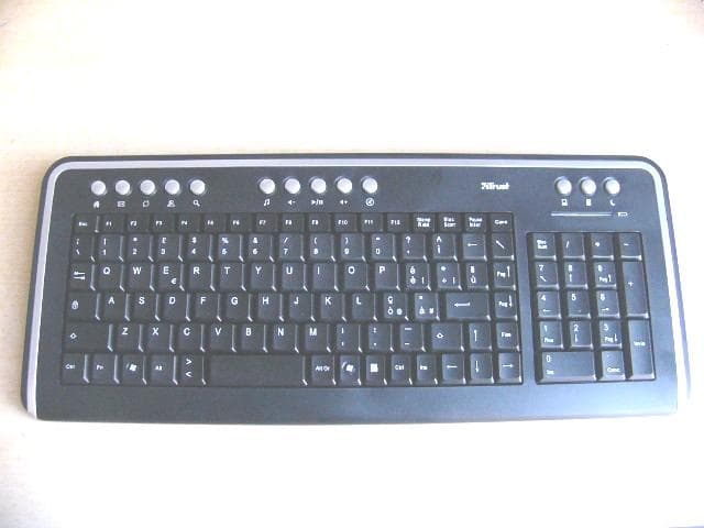
VNK-15555
Dec 12, 2007TRUST US DS-3200 WLOPT SL DESK
Equipment Class
DXX - Part 15 Low Power Communication Device Transmitter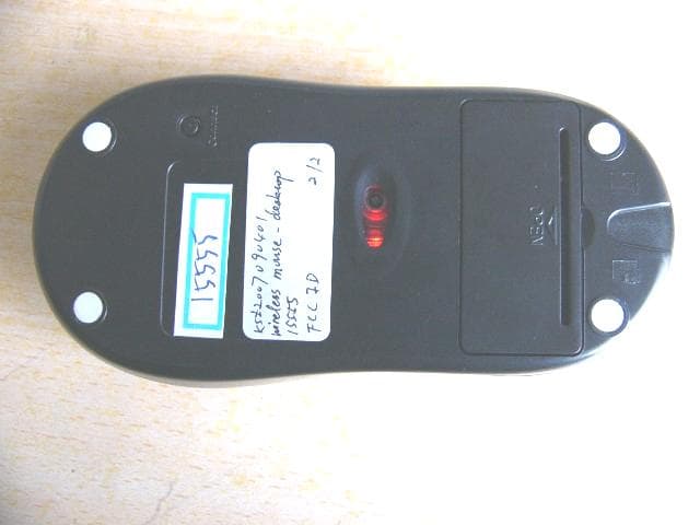
VNK15555
Dec 12, 2007TRUST US DS-3200 WLOPT SL DESK
Equipment Class
DXX - Part 15 Low Power Communication Device Transmitter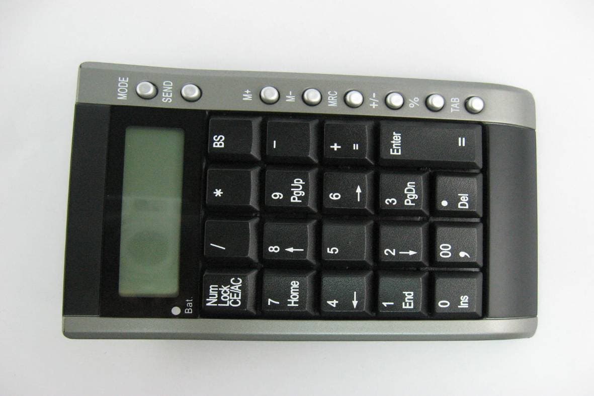
VNK-15560K
Nov 14, 2007KP-4100p Wireless Calculator Keypad & Mouse
Equipment Class
DXX - Part 15 Low Power Communication Device Transmitter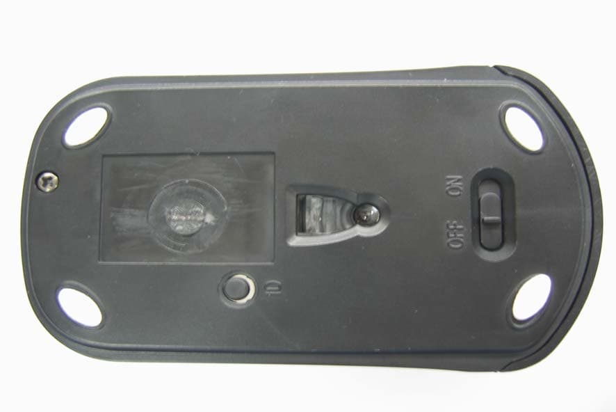
VNK-15560M
Nov 14, 2007KP-4100p Wireless Calculator Keypad & Mouse
Equipment Class
DXX - Part 15 Low Power Communication Device Transmitter