VO5HEADSETBluetooth Headset
SANMY Technology Co., Ltd.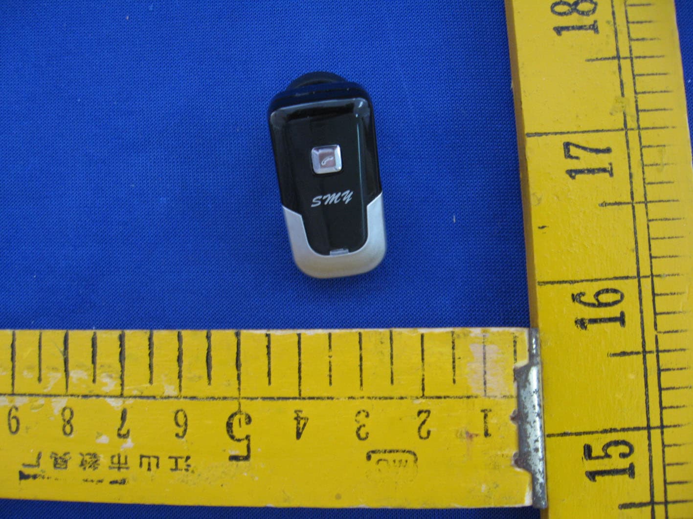
Click to zoom
Application Details
- Equipment Class
- DSS - Part 15 Spread Spectrum Transmitter
- Date of Grant
- Nov 08, 2007
- Application Purpose
- Original Equipment
- Date of Application
- Nov 08, 2007
- Equipment Note
- Bluetooth Headset
- Frequency Range
- 2402.00000000 - 2480.00000000
- Company
- SANMY Technology Co., Ltd.
- Country
- China
Documents & Files
Document Text
Text extracted from the exhibit documents filed with the FCC. Open a document above to read the original.
Users Manual
SMY TM SM-057 BLUETOOTH HEADSET ADDITIONAL INFORMATION CONTENTS SPEC. 1.1 features 1.2 YOUR HEADSET OVERVIEW 1.3 KEY-PRESS AND FUNCTION 1.4LEDINDICATOR 1.5 ACCESSORIES 2 HOW TO START 2.1 CHARGING HEADSET 2.2/ TO SWITCH OFF /ON 2.3 PAIRING AND CONNECTING 3 TAL K 3.1 MAKING A CALL 3.2 ENDING A CALL 3.3 REDIALLING THE LAST NUMBER 3.4 ANSWERING A CALL 3.5 ADJUSTING VOLUME 4 important 4.1 before using your headset 4.2 storage your headset 4.3 available distance and compatibility 1SPEC. 1.1FEATURES z AUTOMATIC STANDBY FUNCTION z SUPPORTING REDIALLING A CALL z RECHARGEABLE BATTERY z 1.2 HEADSET OVERVIEW 1.3 FUNCTION z SWITCH ON z SWITCH OFF z ANSWERING A CALL z ENDING A CALL z REDIALLING A CALL 1.4LEDINDICATOR LIGHT z LEDLED z The indicator light will turn to be red when charging ,while the red indicator turns to be off, the headset is fully charged z LED z If the red indicator light turns to flash .that means the battery is low .please charge your headset in time. z LED z The indicator light keeps blue flashing that means headset is paired. z LED z The headset is in active status or standby status when the indicator flashes in blue. 1.5ACCESSORIES MULTI-FUNCTION BUTTON 2 HOW TO START 2.1 CHARGING YOUR HEADSET 2.1.1 Charging your headset by alternating current z 220VAC z Plug the travel adapter into the electrical outlet.(110-220AcV) z z Then plug the other side of the travel adapter into the headset socket. 2.1.2 USING THE CAR KITS CHARGER z z Plug the car kit charger into the car power outlet. z z Then plug the other side of the car kit charger into the headset socket 2.1.3 IMPORTANT z z Before using your headset for the first time. make sure the battery is not low. This is a rechargeable headset. z z The charger must be matched with this manufacturer’s mold. z 5.5VDC~6VDC z The voltage should between 5.5VDC~6.0VDC. z z The red indicator light displayed during changing ,when the indicator light turns off, that is fully charged z 10~20() z When you keep the headset for long time no use. It’s normal that the red indicator will keeps not display while after 10—20 minutes start to display z 2.2/ to switch off /on CAR KIT CHARGER Ac charger z 3 To switch on ,press and hold the multi-function key for about 3 seconds. until the blue indicator turns on lasting blue. z z 3 z To switch off ,press and hold for about 3 seconds. until the red indicator turns off 2.3 PAIRING WITH YOUR BLUETOOTH PHONE z z Ensure that the headset is power off z 3 z Press and hold the multi-function for about 3 seconds until the the blue indicator turns to be off,then release. z ,, z Set your Bluetooth phone to discover the headset by following your phone’s guide ,typically ,the steps involve going to a ‘ setup’ ‘connect’or ‘bluetooth’ menu on your phone and then selecting the option to discover Bluetooth devices. z SM-M057,, , Your phone will find the SM-057 headset and ask if you want to pair with is. confirm this by pressing the yes or ok key . z z 0000(4), z Enter a passkey or PIN,0000(4 zeros) the press the yes or ok key . z z Select the “connect”, then start to create a connect between the headset and mobile. z ,2, z If successful, the blue indicator will flash in every 2 seconds. If not, please reconnect again. 3 Talk 3.1 Making a call z Make sure the headset has been connected with the phone already. Then make a call as usual by your phone 3.2 ENDING A CALL z z Press the multi-function once. 3.3 z 2 z Press the multi-function twice ,within 2 seconds. 3.4 ANSWERING A CALL z , z After you hearing the ring tone ,press the multi-function once 3.5 ADJUSTING THE VOLUME z . z Please adjust the volume on your mobile phone 4IMPORTANT 4.1BEFORE USING YOUR HEADSET z 2.0 z Please check whether you phone has the Bluetooth devices,your headset is compatible with most phone that are compliant with Bluetooth version2.0 and support the headset and/or hand-free profiles ensure that your phone has Bluetooth capability by visiting your phone manufacturer’s website 4.2STORAGE YOUR HEADSET z Ensure your headset is power off. z -1545 z Avoid storage at high temperatures(-15-45) z z .Do not expose the headset or any of its supplied parts to rain or other liquids 4.3 operation range and interfering z 10 ,, z The operation range is about 10m. pairing a unique link between Bluetooth and pone. Pls keep away from the wireless devices when you are calling, it will not interfere with any other electric equipments . *** Caution *** This device complies with part 15 of the FCC Rules. Operation is subject to the following two conditions: (1) This device may not cause harmful interference, and (2) this device must accept any interference received, including interference that may cause undesired operation. Changes of modifications not expressly approved by the party responsible for compliance could void the user ’s authority to operate the equipment. FCC statement Note: This equipment has been tested and found to comply with the limits for a Class B digital device, pursuant to part 15 of the FCC Rules. These limits are designed to provide reasonable protection against harmful interference in a residential installation. This equipment generates, uses and can radiate radio frequency energy and, if not installed and used in accordance with the instructions, may cause harmful interference to radio communications. However, there is no guarantee that interference will not occur in a particular installation. If this equipment does cause harmful interference to radio or television reception, which can be determined by turning the equipment off and on, the user is encouraged to try to correct the interference by one or more of the following measures: --Reorient or relocate the receiving antenna. --Increase the separation between the equipment and receiver. --Connect the equipment into an outlet on a circuit different from that to which the receiver is connected. --Consult the dealer or an experienced radio/TV technician for help.
Block Diagram
R O M R A M B a s e b a n d D SP C P U 2.4GHz Radio I/O F il t e r Y 1 = 16 M H z SP I UA R T / U S B P I O P C M A u d i o I n / O u t B a tt e r y C h a r g e r B u tt on M i c r o p hon e S p ea k e r B a tt e r y B u l e T oo t h H ea d s e t E l ec t r o c i r c u i t C h a r t
External Photos
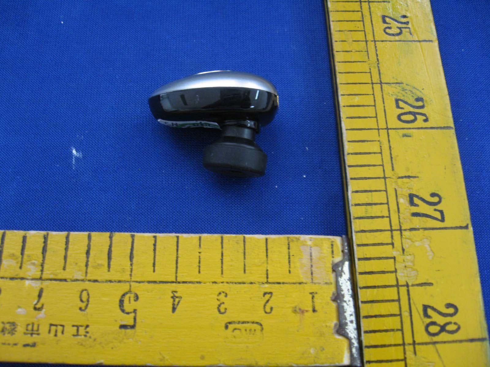
External Photos
ID Label/Location Info
10.7mm 11mm FCC ID:VO5HEADSET SM-057
Internal Photos
Page 1 of 2 Internal Photos Page 2 of 2
Operational Description
Bean Plus Operation Description The Bean Plus use the Bluetooth Technology to connect with Mobile which have built in Bluetooth .Using the HFP&profile of Bluetooth to have call function. The following is the function subject: 1. call ID display when there is a incoming call 2. receive call 3. end call 4. volume control 5. last num redial 6. active the voice dialing when mobile support this function 7. showing mobile phone status. The function theory as below: 1. function diagram `` `` 2. The Mobile Wireless Headset uses a short-range wireles communication Technology. The design applied is in in ternational identification ISM (Industrial Scientific and Medical )frequency bandwidth environment that is 2.4GHz—2.48GHz bandwidth. 3. The Mobile Wireless Headset is a wireless mono headset Within a range of 10 meters, This headest can connect to other Bluetooth devices which have built-in audio gateway,such as Mobile Phone,Desktop,Notebook Computer or PDA etc... Filter Bluetooth Module Speaker MIC Battery Key-press RAM XTAL 16M
Schematics
1 2 34 ABCD 4 3 2 1 D CBA C6 5P6 +1.8V SPI-MISO SPI-CSB SPIO_MOSI SPI_CLK UART_RTS UART_CTS UART_TXUART_RX R51M(NC) R647K R747K Y116M C910P C83P9 C4 15P R1047K R847K +3.6V +1.8V P1TE C12 10n C5 100n R1147K R947K R26 2.2R L1 2.2nH C22P A1 GIGAANT 3030A6250-01 L2 15nH C14 15P +1.8V C1NC C15 15P +1.8V +1.8V +1.8V C7 4.7uF Unbalanced 1 GND 5 Balanced 4 Balanced 6 GND 7 DC 2 GND 8 NC 3 T1 DBF81F101-6 C18 10n C19 4.7uF L6 33uH +1.8V 1 A S1RB551 BAT SP1 R SPEAKER R35 4.7K R37 4.7K R36 4.7K +1.8V PIO8PIO6PIO7 SCL 6 GND 4 SDA 5 VCC 8 WP 7 A0 1 A1 2 A2 3 U2 AT24C32 R33 10R C23 104 MIC1-42dB R32 2.2K L3 15nH C20 15P R47150K 1% R46 220K 1% SW3 ON/OF +3.6V SW2 F2 SW1 VOL+ AIO0 VIN 1 GND 2 SHDN 3 BYP 4 VOUT 5 U3 RT9167-2.7V C3810n +3.6V SW4 V- +3.6V C37 4.7uF C39 4.7uF C35 4.7uF PIO9 123456 J2 UART 123456 J1SPI SPI-MISO SPI-CSB SPIO_MOSI SPI_CLK UART_RTS UART_CTS UART_TXUART_RX R63 2R2 G 0 5V 1 D- 2 D+ 3 G 4 G 0 J3 CHANG C47 1uF R62 2R2 +5V C1147n C10 47n BAT 3.6V LED2Blue LED1 RED R45120 R44 100 +3.6V SW7 POWER ON/OFF BAT PIO9 PIO1 PIO0 R1247K PIO2 R1347K +3.6V C3 100n AIO0 +5V +3.6V R3 150K 1% R2 220K 1% MIC+ MIC- PIO4 PIO4 MIC- MIC+ MIC- PIO8PIO6PIO7 ON PIO1PIO0PIO2 C13 5p6 PIO3T3PIO10T10PIO11T11 Title BC413159 8X8 Revision 0.05 Date 3-AUG-2005 PIO[0] A1 PIO[2] A2 PIO[11] A3 PIO[9] A4 LX A6 VSS_BAT A7 VDD_BAT A8 LED[0] A9 LED[1] A10 VDD_CHG A11 VDD_PIO B1 PIO[1] B2 PIO[3] B3 PIO[10] B4 NC B5 VDD_MEM B6 NC B7 VDD_MEM B8 NC B10 VDD_RADIO C1 VSS_RADIO C2 AUX_DAC C3 VSS_PADS4 C4 VSS_MEM C5 NC C6 VSS_MEM C7 VSS_PADS3 C8 TEST_EN C10 RX_IN D1 VSS_RADIO D2 NC D3 VSS_PADS2 D9 RESETB D10 VDD_PADS D11 TX_B E1 VSS_RADIO E2 VSS_SHIELD E3 VSS_CORE E9 NC E10 VDD_CORE E11 TX_A F1 VSS_RADIO F2 NC F3 PIO[4] F9 PIO[5] F10 VSS_LO G1 VSS_LO G2 NC G3 NC G10 VREG_IN H1 VDD_VCO H2 VREG_EN H3 NC H10 SPKR_N J1 SPKR_P J2 VSS_LDO J3 VSS_ANA J4 VSS_ANA J5 AIO[0] J6 VDD_MEM J7 TEST[2] J8 VSS_PADS1 J9 NC J10 VREG_OUT K1 VSS_ANA K2 VSS_ANA K3 XTAL_OUT K4 NC K5 NC K6 TEST[1] K7 VDD_MEM K8 VDD_ANA L1 MIC_P L2 MIC_N L3 XTAL_IN L4 VDD_ANA1 L5 AIO[1] L6 USB_DN L9 USB_DP L10 VDD_USB L11 PIO[8] A5 PIO[7] G9 PIO[6] F11 UART_RX K10 UART_TX K9 UART_RTS L8 UART_CTS K11 SPI_CLK C11 SPI_MOSI C9 SPI_MISO B11 SPI_CSB B9 AIO[2] L7 PCM_SYNC H9 PCM_IN J11 PCM_OUT G11 PCM_CLK H11 U1BC413159 R612.2K RESET +1.8V Q1 3904 R4150K R80220K 1% C80105 RESET +1.8V +1.8V
Test Report
SHENZHEN SETEK TECHNOLOGY CO., LTD. Report No.:SE07FCI049R FCC TEST REPORT REPORT NO.:SE07FCI049R MODEL NO.: SM-057 LISTED MODELS: SM-058, SM-059, SM-060, SM-049 RECEIVED: Oct 10, 2007 TESTED: Oct 10, 2007 to Oct 20, 2007 APPLICANT: SANMY Technology Co., Ltd ADDRESS: No6,Hesheng Industrial Area, Heping High Tech Zone, Fuyong Town, Shenzhen, China ISSUED BY: SHENZHEN SETEK TECHNOLOGY CO., LTD. LAB LOCATION: 2/F,A3 Bldg,East Industry Zone,Overseas Chinese Town, Shenzhen,China This test report consists of 60 pages in total, it may be duplicated completely for legal use with the approval of the applicant, It should not be reproduced except in full, without the written approval of our laboratory, The test results in the report only apply to the tested sample. SHENZHEN SETEK TECHNOLOGY CO., LTD. Our website: www.setek.com.cn E-mail:[email protected] TEL:86-755-26966362 FAX: 86-755-26966270 SHENZHEN SETEK TECHNOLOGY CO., LTD. Report No.:SE07FCI049R Page 2 of 60 The device described above is tested by SHENZHEN SETEK TECHNOLOGY CO., LTD. to determine the maximum emission levels emanating from the device and the severe levels of the device can endure and its performance criterion. This report applies to above tested sample only and shall not be reproduced in part without written approval of SHENZHEN SETEK TECHNOLOGY CO., LTD. Prepared for : SANMY Technology Co., Ltd Address : No6,Hesheng Industrial Area, Heping High Tech Zone, Fuyong Town, Shenzhen, China Product : BLUETOOTH HEADSET Model No. : SM-057, SM-058, SM-059, SM-060, SM-049 Trademark : SMY Test Standard : FCC Part 15 Paragraph 15.203, Paragraph 15.207 and Paragraph 15.247 Prepared by : SHENZHEN SETEK TECHNOLOGY CO., LTD. Address : 2/F, A3 Bldg, East Industry Zone, Overseas Chinese Town, Shenzhen, China FCC Registration Number: 966959 Tel: (86-755) 26966362 Fax:(86-755) 26966270 Prepared by : (Engineer) Reviewer by : (Project Engineer) Approved by : (Manager) Report Number : SE07FCI049R Date of Test : Oct 10, 2007 to Oct 20, 2007 Date of Report : Oct 20, 2007 SHENZHEN SETEK TECHNOLOGY CO., LTD. Report No.:SE07FCI049R Page 3 of 60 TABLE OF CONTENTS Description Page The Report Description 1. GENERAL INFORMATION ............................................................................................................ 5 1.1. Description of Device (EUT) ....................................................................................................................5 1.2. Description of Support Device..................................................................................................................6 1.3. Summary of test results.............................................................................................................................6 1.4. List of Measuring Equipments Used.........................................................................................................7 1.5. Test Facility ..............................................................................................................................................7 1.6. Measurement Uncertainty .........................................................................................................................7 2. ANTENNA REQUIREMENT ......................................................................................................... 8 2.1. Standard Applicable..................................................................................................................................8 2.2. Antenna Connected Construction .............................................................................................................8 3. POWER LINE CONDUCTED MEASUREMENT ....................................................................... 9 3.1. Test Equipment .........................................................................................................................................9 3.2. Block Diagram of Test Setup....................................................................................................................9 3.3. Power Line Conducted Emission Measurement Limits(Class B) .............................................................9 3.4. Configuration of EUT on Measurement .................................................................................................10 3.5. Operating Condition of EUT ..................................................................................................................10 3.6. Test Procedure ........................................................................................................................................10 3.7. Power Line Conducted Emission Measurement Results ........................................................................10 4. TEST OF HOPPING CHANNEL BANDWIDTH....................................................................... 13 4.1 Applicable Standard .......................................................................................................................................13 4.2 EUT Setup ......................................................................................................................................................13 4.3 Test Equipment List and Details ....................................................................................................................13 4.4 Test Procedure................................................................................................................................................13 4.5 Test Result......................................................................................................................................................13 5. TEST OF HOPPING CHANNEL SEPARATION ...................................................................... 17 5.1 Applicable Standard .......................................................................................................................................17 5.2 EUT Setup …
Text truncated - open the document above for the full version.
Test Report
SHENZHEN SETEK TECHNOLOGY CO., LTD. Report No.:SE07FCI049R Page 53 of 60 APPENDIX I (Compliance Statements) SHENZHEN SETEK TECHNOLOGY CO., LTD. Report No.:SE07FCI049R Page 54 of 60 Subclause 15.247 (a) – Equal Hopping Frequency Use Requirement: Each of the transmitter’s hopping channels is used equally on average. The EUT complies with the Bluetooth RF specifications. For details refer to the Bluetooth standard. Subclause 15.247 (a) – Receiver Input Bandwidth Requirement: The associated receiver(s) complies with the requirement that its input bandwidth matches the bandwidth of the transmitted signal. The receiver bandwidth is equal to the receiver bandwidth in the 79 hopping channel mode, which is 1 MHz. The receiver bandwidth was verified during Bluetooth RF conformance testing. Subclause 15.247 (a) – Receiver Hopping Capability Requirement: The associated receiver has the ability to shift frequencies in synchronisation with the transmitted signals. The EUT complies with the Bluetooth RF specifications. For details refer to the Bluetooth standard. SHENZHEN SETEK TECHNOLOGY CO., LTD. Report No.:SE07FCI049R Page 55 of 60 Subclause 15.247 (a) – Hopping Sequence Requirement: The hopping sequence is generated and provided with an example.
Test Setup Photos
Radiated Emission Setup Photo
Contact Information
Applicant
Amanda Zhang(General Manager Assistant)
Test Firm
Shenzhen SETEK Technology Co., Ltd.Phenix Zhang
Technical Specifications
| # | Rule Parts | Frequency Range | Power Output |
|---|---|---|---|
| 1 | 15C | 2.40 GHz - 2.48 GHz | 600.00 µW |
Other Applications from SANMY Technology Co., Ltd.
VO5SM-062
Mar 05, 2008Bluetooth Headset
Equipment Class
DSS - Part 15 Spread Spectrum Transmitter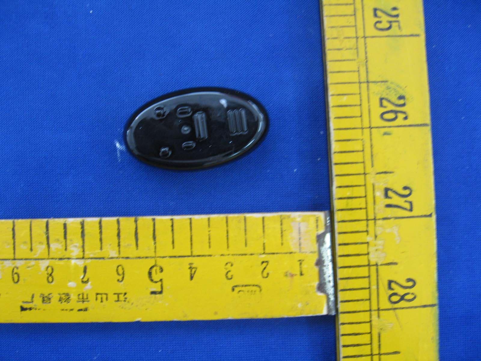
VO5SM-S36
Mar 04, 2008Bluetooth Headset
Equipment Class
DSS - Part 15 Spread Spectrum Transmitter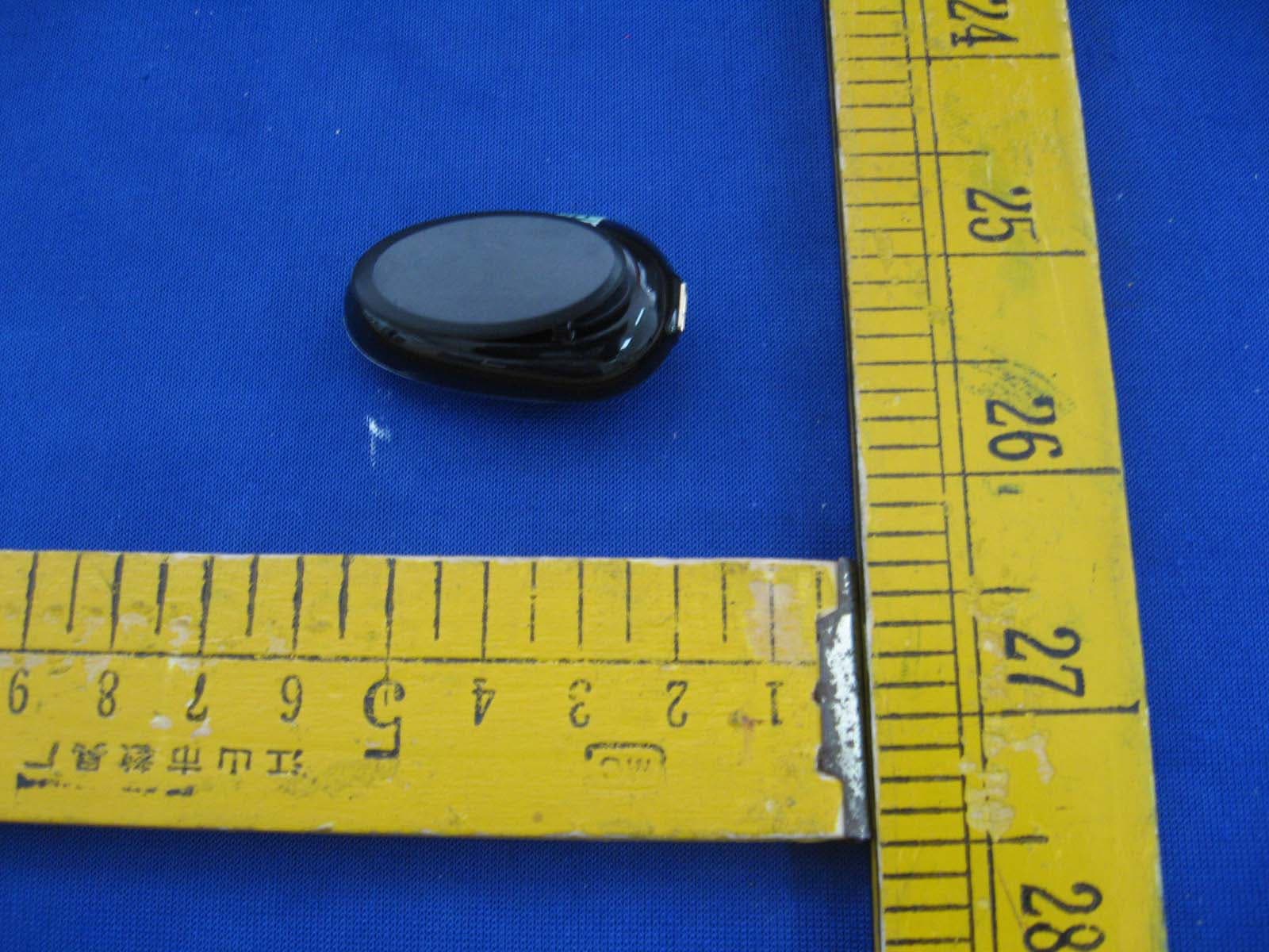
VO5SM-S38
Mar 02, 2008Bluetooth Headset
Equipment Class
DSS - Part 15 Spread Spectrum Transmitter