VOZFK126MWWireless Silicone Keyboard
Jinghong Industrial (Hong Kong) Co., Limited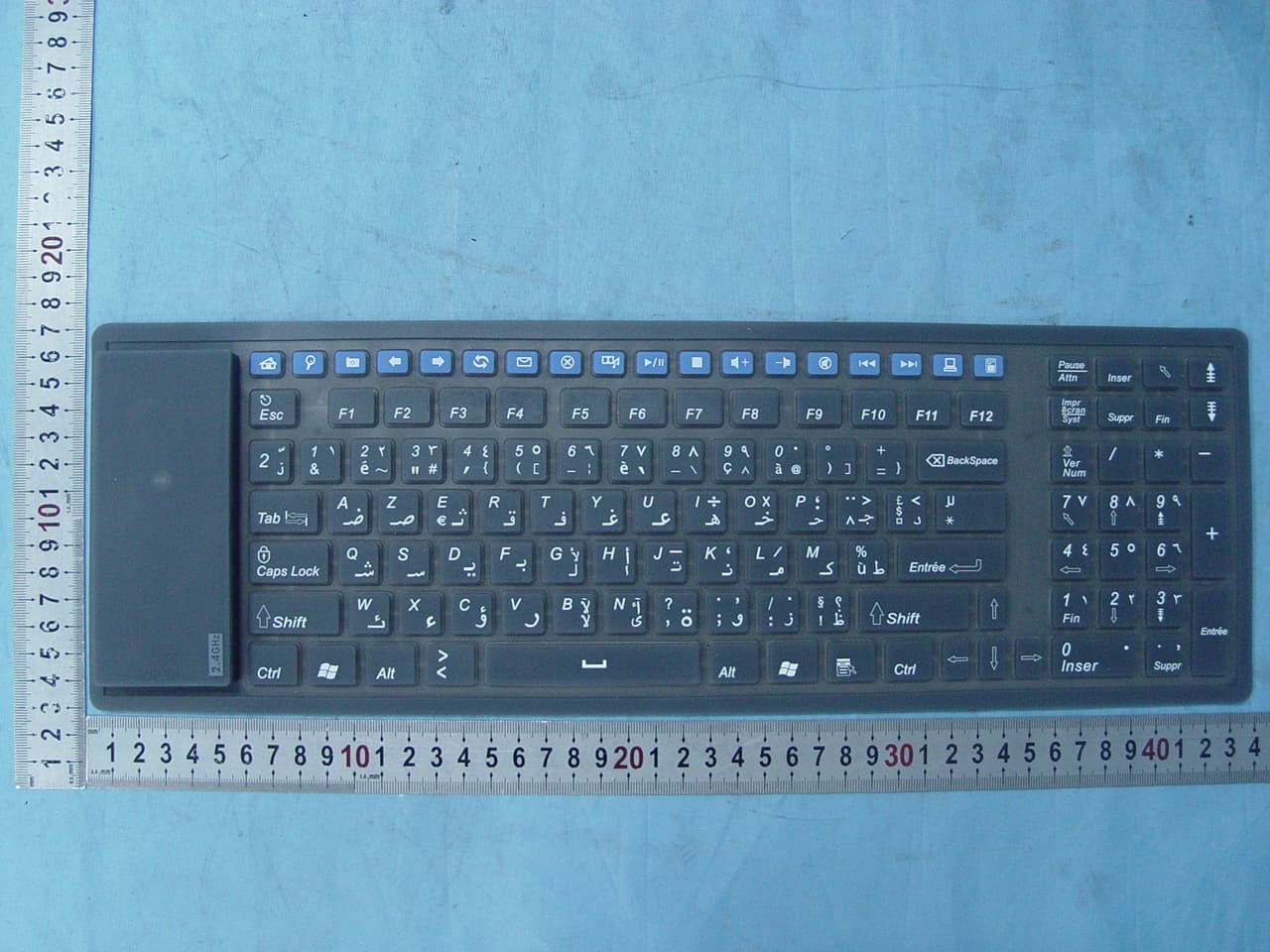
Click to zoom
Application Details
- Equipment Class
- DXX - Part 15 Low Power Communication Device Transmitter
- Date of Grant
- Sep 27, 2007
- Application Purpose
- Original Equipment
- Date of Application
- Sep 27, 2007
- Equipment Note
- Wireless Silicone Keyboard
- Frequency Range
- 2405.00000000 - 2477.00000000
- Country
- China
Documents & Files
Document Text
Text extracted from the exhibit documents filed with the FCC. Open a document above to read the original.
Users Manual
RF Keyboard User' s Guide work frequency:2.4GHz Welcome Your wireless keyboard uses digital radio technology to connect with your computer. The communication between the keyboard and your computer is achieved by using highly precise and reliable radio waves. It does not require in-sight usage as the infra-red one does, since radio waves can penetrate non-metallic objects as: wood, mirror etc, and it can radiate signals full 360 degree direction! So you can place your receiver anywhere. By using our keyboard, you do not have to let bulky cables occupy your table. Your wireless keyboard comes with multimedia keys and an internet access key, which is compatible with Windows ME, Windows 2000,Windows XP. The multimedia control function is then installed in your computer, which means you can access through the internet quickly, too. The Batteries The cordless keyboard uses two AAA alkaline batteries, they can be used for more than six months under proper usage. Installing the Batteries into the Keyboard Step 1.Remove the battery compartment cover (on the bottom of the keyboard) as the arrow in the picture to open it. Step 2.Insert the AA alkaline batteries as shown inside the battery compartment. Step 3.Replace the cover carefully. We’ve also developed low voltage warning circuit. During using of the keyboard, when the voltage is low, the keyboard will send the low voltage signal to the receiver, then the marked COM red LED will keep flashing, reminding you of low voltage warning signal, until there, no warning signal from the keyboard. When there, low voltage signal warning, please replace the batteries in time, we suggest you use same specification batteries, and avoid usage of new and old ones. When you use the keyboard, if you find the input of the letters is slow, abnormal, or having no reaction, may be it, low voltage, please check the batteries. Indicating lights of the Receiver 1.COM: communication light/low voltage warning light. When receiving positive signals from the mouse or keyboard, the light will be shinning. When the wireless keyboard or mouse is low voltage, there,s warning signal being sent to the receiver, the COM indicating light will keep flashing, until there,s no warning code in the signal. Connecting the Receiver Your RF keyboard use reliable radio waves to communicate with your computer and does not have bulky cables. Radio waves transmitted by the keyboard are receiver by the receiver, then through the receiver connect to your personal computer. Establishing the Communication Channel between the Keyboard and the Receiver 1.Press the CONNECT button at the left side of the keyboard once. 2.Then, within 5 seconds, press the CONNECT button on the receiver. Waiting for 10 seconds, if succeed in communication, the keyboard should be used normally, at the same time the communication indicator LED will light on. If the keyboard fails to be working normally after 10 seconds, please repeat the previous steps again. Working Circumstance After you have installed the receiver, you are ready to place the keyboard on your desktop. Before you enjoy a great feeling of convenience from the advanced digital, please check the following aspects to optimize the use of your wireless keyboard: For optimal performance, placing the receiver at least 20 centimetres away from the PC case, monitor, external disk drive, or other electrical devices, just to prevent disturbance. Radio waves can penetrate through non-metallic objects like: wood, mirror, etc, and can radiate signal full 360 degree direction, but it can not penetrate through metallic objects, so, keyboard and mouse and receiver should not be placed on metal desktop, suggest placing them at least 20 centimetres away from such metal objects. Between the keyboard and receiver, there should not be big metal plate which will affect the transmitting and the receiving of radio signals. We give out the standard testing receiving distance based under the normal radio wave interference circumstance. Generally the distance can be a little longer. But if there are stir machine, motor, or electric drill, etc, such interference nearby may cause the cursor moving slowly, abnormally, etc. Then you can shorten the distance between the receiver and the keyboard, so as to overcome such disturbance. Using the Hot Keys The cordless keyboard comes with eight multimedia keys and four internet keys. All of these hot keys are compatible with Windows ME, 2000, XP. The Functions of Hot Keys 1.The eight hot keys are compatible with the Windows Media Player, (Start-Program- Accessory-entertainment-Windows Media Player) 1) Media 2) Play/Pause 3) Prev Track 4) Next Track 5) Volume- 6) Volume+ 7) Mute 8) Stop 2. Internet Keys 1) WWW 2) E-mail 3) Forward 4) Backward 5)Search 6)Refresh 7)Favorites 8)WWW Stop 3:Windows Power Key 1)My computer 2)Calculator 3)Power 4)Sleep 5)Wake Up FCC STATEMENT 1. This device complies with Part 15 of the FCC Rules. Operation is subject to the following two conditions: (1) This device may not cause harmful interference, and (2) This device must accept any interference received, including interference that may cause undesired operation. 2. Changes or modifications not expressly approved by the party responsible for compliance could void the user’s authority to operate the equipment.
Block Diagram
TX Block Diagram Antenna RF Generator oscillation 26MHZ RF MCU U1 X 32 oscillation 12MHZ U3 DC-DC Setup U2 EEPROM Key Matrix TX FM Modulator RF Amplifier
ID Label/Location Info
FCC Label& Location Info Label Location
Operational Description
TX Operation Description Modulation Type: FSK TX Frequency: 2405M-2477 MHz The is an wireless keyboard with frequency 2.4 GHz. The remote control distance reaches 10 meters. The keyboard is designed with 3 parts: MCU U1(MA1922), RF module URFM (RFM5010) and EEPROM U2 (93C46B). U3 converts battery voltage to a stable DC 3V for supplying the keyboard. U1 receives signals of MB1 when working. All signals are processed in U1 and are encoded. URFM is a wireless module. It contains of functions of modulation, amplification and transmission by antenna. * END *
Schematics
123456 A B C D 654321 D C B A Title NumberRevisionSize B Date:18-Sep-2007Sheet of File:F:\IC \\2.4G RF\RFM5010 \ combo\MA1922RFM5010.DDB Drawn By: SPI DISPI CK SPI DOSPI CS VDD2 VDD1 P42 / EEP CS P43 / EEP SK / BTL CS 1 SK 2 DI 3 DO 4 GND 5 NC 6 NC 7 VCC 8 U2 93LC46A P10 / COL2 P03 / COL11 P02 / COL12 P01 / COL13 P00 / COL14P23 / COL15 P22 / COL16 P21 / COL17 P27 / COL3 P25 / COL5 P24 / COL6 P07 / COL7 P06 / COL8 P05 / COL9 P04 / COL10 P26 / COL4 P11 / COL1 P12 / COL0 P37 / ROW7 P36 / ROW6 P35 / ROW5 P34 / ROW4 P33 / ROW3 P32 / ROW2 P31 / ROW1 P30 / ROW0 P20 / COL18 / EEP IO P41 / BTL DT P13 / SW_ID P17 / V2 P16 / V1 P15 / Z2 P14 / Z1 P20 / COL18 / EEP IO NRZ IO P17 64 P52 1 XRESET 2 XEN_EXROM 7 XEN_PROBE 4 ORFIN_13M 5 ORFOUT_13M 6 RF24G_CK_OUT 3 PDVREF 8 PDSIN 9 VSS 10 OSCI 11 OSC2 12 VDD 13 REGVA 14 REGVREF 15 D+_CLK 16 D-_DATA 17 VD1 18 P42 19 P43 20 P20 21 P21 22 P22 23 P23 24 P00 25 P01 26 P02 27 P03 28 P04 29 P05 30 VPP 31 VSS 32 P06 33 P07 34 P24 35 P25 36 P26 37 P27 38 P10 39 P11 40 P12 41 P13 42 P30 43 P31 44 P32 45 P33 46 P34 47 VSS 48 49 P35 50 P36 51 P37 52 P40 53 P41 54 P44 55 P45 56 P46 57 P47 58 P50 59 P51 60 P14 61 P15 62 P16 63 U1 MA1922 X32 12MHz C35 *20pF C34 *20PF VDD2 C36 100uF P41 / BTL DT P13 / SW_ID P17 / V2 P16 / V1 P15 / Z2 P14 / Z1 SW_Z SW_V V 4 Z 2 ( Volome ) ( Whell up & down ) R35 470K VBT SWID LED_BTL R33 560 VDD1 VOUT 1 VDD 3 GND 2 U5 AIC1680N22 P42 / EEP CS P43 / EEP SK / BTL P43 / EEP SK / BTL D61 RB421 C65 0.1uF C62 0.1uF VBT C61 220uF _ + BT1 2AA*2 VDD1 C64 120uF L61 100uH VSS 1 VIN 3 VOUT 2 U3 RTS9261-33 VDD2 VOUT 3 VSS 1 VIN 2 U4 XC6206-27 C21 0.1uF + C20 100uF MA1922 + RFM5010 V1.0 VDD1 SPI DOSPI CS NRZ IO SPI DISPI CK VOUT 3 VSS 1 VIN 2 U6 XC6206-25 2.5V 2.5V C69 0.1uF C68 100uF Csn 1 GDO0 2 GDO2 3 SO 4 SCLK 5 SI 6 VCC 7 GND 8 ANT URF RFM5010 P10 / COL2 P03 / COL11P02 / COL12P01 / COL13P00 / COL14P23 / COL15P22 / COL16P21 / COL17 P27 / COL3P25 / COL5P24 / COL6P07 / COL7P06 / COL8P05 / COL9 P04 / COL10 P26 / COL4P11 / COL1P12 / COL0 P37 / ROW7P36 / ROW6P35 / ROW5P34 / ROW4P33 / ROW3P32 / ROW2P31 / ROW1P30 / ROW0 123456789 10111213141516171819202122232425262728 MB1 MLK P33 / ROW3 P1 C18 P2 C19
Test Report
Page 1of 40 FCC ID: VOZFK126MW ACCURATE TECHNOLOGY CO. LTD REPORT NO. ATE20072280 FCC CERTIFICATION On Behalf of Jinghong Industrial (Hong Kong) Co., Limited Wireless Silicone Keyboard Model No.: FK-126MW FCC ID: VOZFK126MW Prepared for : Jinghong Industrial (Hong Kong) Co., Limited Address : La 2, Block B, Hengmingzhu, Bao Tian Industry, Qianjin 2 Rd., Baoan District, Shenzhen, China Prepared by : ACCURATE TECHNOLOGY CO. LTD Address : F1, Bldg. A, Changyuan New Material Port, Keyuan Rd. Science & Industry Park, Nanshan, Shenzhen, Guangdong P.R. China Tel: (0755) 26503290 Fax: (0755) 26503396 Report Number : ATE20072280 Date of Test : September 18, 2007 Date of Report : September 21, 2007 Page 2of 40 FCC ID: VOZFK126MW ACCURATE TECHNOLOGY CO. LTD REPORT NO. ATE20072280 TABLE OF CONTENTS Description Page Test Report Certification 1. GENERAL INFORMATION .......................................................................................................... 4 1.1. Description of Device (EUT)....................................................................................................................4 1.2. Description of Test Facility ......................................................................................................................4 1.3. Measurement Uncertainty.........................................................................................................................4 2. MEASURING DEVICE AND TEST EQUIPMENT ..................................................................... 5 3. FUNDAMENTAL AND HARMONICS RADIATED EMISSION MEASURMENT ................ 6 3.1. Block Diagram of Test Setup....................................................................................................................6 3.2. The Emission Limit ..................................................................................................................................6 3.3. Configuration of EUT on Measurement ...................................................................................................7 3.4. Operating Condition of EUT ....................................................................................................................7 3.5. Test Procedure ..........................................................................................................................................7 3.6. The Field Strength of Radiation Emission Measurement Results ............................................................8 4. RADIATED EMISSION FOR FCC PART 15 SECTION 15.249(D)......................................... 11 4.1. Block Diagram of Test Setup..................................................................................................................11 4.2. The Emission Limit For Section 15.249(d) ............................................................................................11 4.3. EUT Configuration on Measurement .....................................................................................................13 4.4. Operating Condition of EUT ..................................................................................................................13 4.5. Test Procedure ........................................................................................................................................13 4.6. The Emission Measurement Result ........................................................................................................14 5. BAND EDGES ................................................................................................................................. 17 5.1. The Requirement ....................................................................................................................................17 5.2. EUT Configuration on Measurement .....................................................................................................17 5.3. Operating Condition of EUT ..................................................................................................................17 5.4. Test Procedure ........................................................................................................................................17 5.5. The Measurement Result ........................................................................................................................18 6. ANTENNA REQUIREMENT........................................................................................................ 19 6.1. The Requirement ....................................................................................................................................19 6.2. Antenna Construction .............................................................................................................................19 APPENDIX I ( TEST CURVES) (20pages) Page 3of 40 FCC ID: VOZFK126MW ACCURATE TECHNOLOGY CO. LTD REPORT NO. ATE20072280 Test Report Certification Applicant : Jinghong Industrial (Hong Kong) Co., Limited Manufacturer : Jinghong Industrial (Hong Kong) Co., Limited EUT Description : Wireless Silicone Keyboard (A) MODEL NO.: FK-126MW (B) SERIAL NO.: N/A (C) POWER SUPPLY: DC 3.0V (AAA battery ̄2) Measurement Procedure Used: FCC Rules and Regulations Part 15 Subpart C Section 15.249: 2006 & ANSI C63.4: 2003 The device described above is tested by ACCURATE TECHNOLOGY CO. LTD to determine the maximum emission levels emanating from the device. The maximum emission levels are compared to the FCC Part 15 Subpart C Section15.249 limits. The measurement results are contained in this test report and ACCURATE TECHNOLOGY CO. LTD is assumed full responsibility for the accuracy and completeness of these measurements. Also, this report shows that the Equipment Under Test (EUT) is to be technically compliant with the FCC requirements. This report applies to above tested sample only. This report shall not be reproduced in part without written approval of ACCURATE TECHNOLOGY C…
Text truncated - open the document above for the full version.
Contact Information
Applicant
Alan Zhu(General Manager)
Test Firm
Accurate Technology Co., Ltd.Sean Liu
Technical Specifications
| # | Rule Parts | Frequency Range | Power Output |
|---|---|---|---|
| 1 | 15C | 2.40 GHz - 2.48 GHz | - |
Other Applications from Jinghong Industrial (Hong Kong) Co., Limited
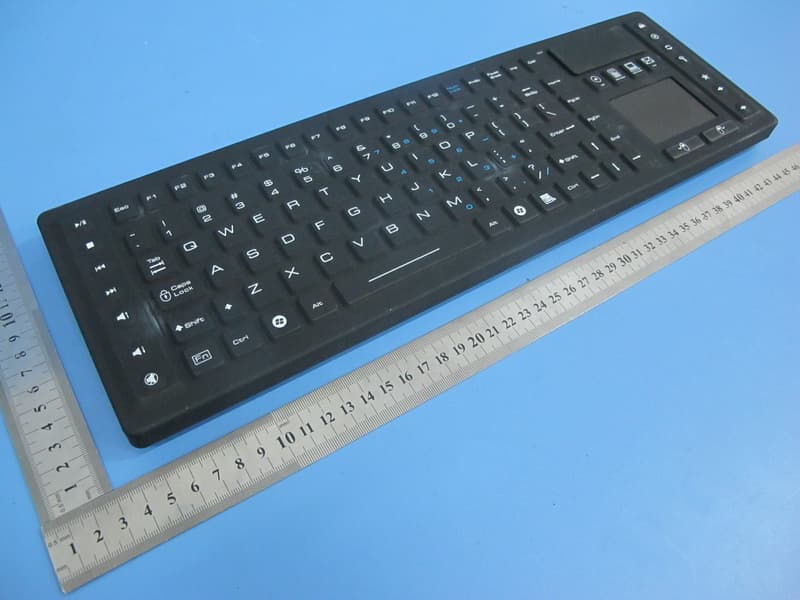
VOZ-TBK104
May 07, 2015Industrial Wireless Keyboard
Equipment Class
DXX - Part 15 Low Power Communication Device Transmitter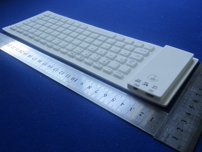
VOZ-FR85BT
Jul 06, 2012Silicone Flexible Bluetooth Keyboard
Equipment Class
DSS - Part 15 Spread Spectrum Transmitter