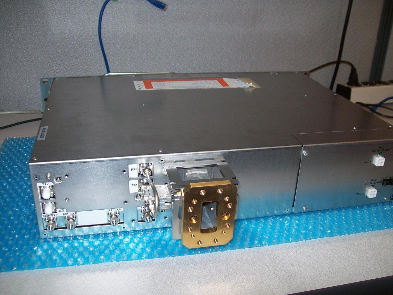
VQL58155NNLite N 5.8 GHz Digital Microwave Radio
NEC Corporation of America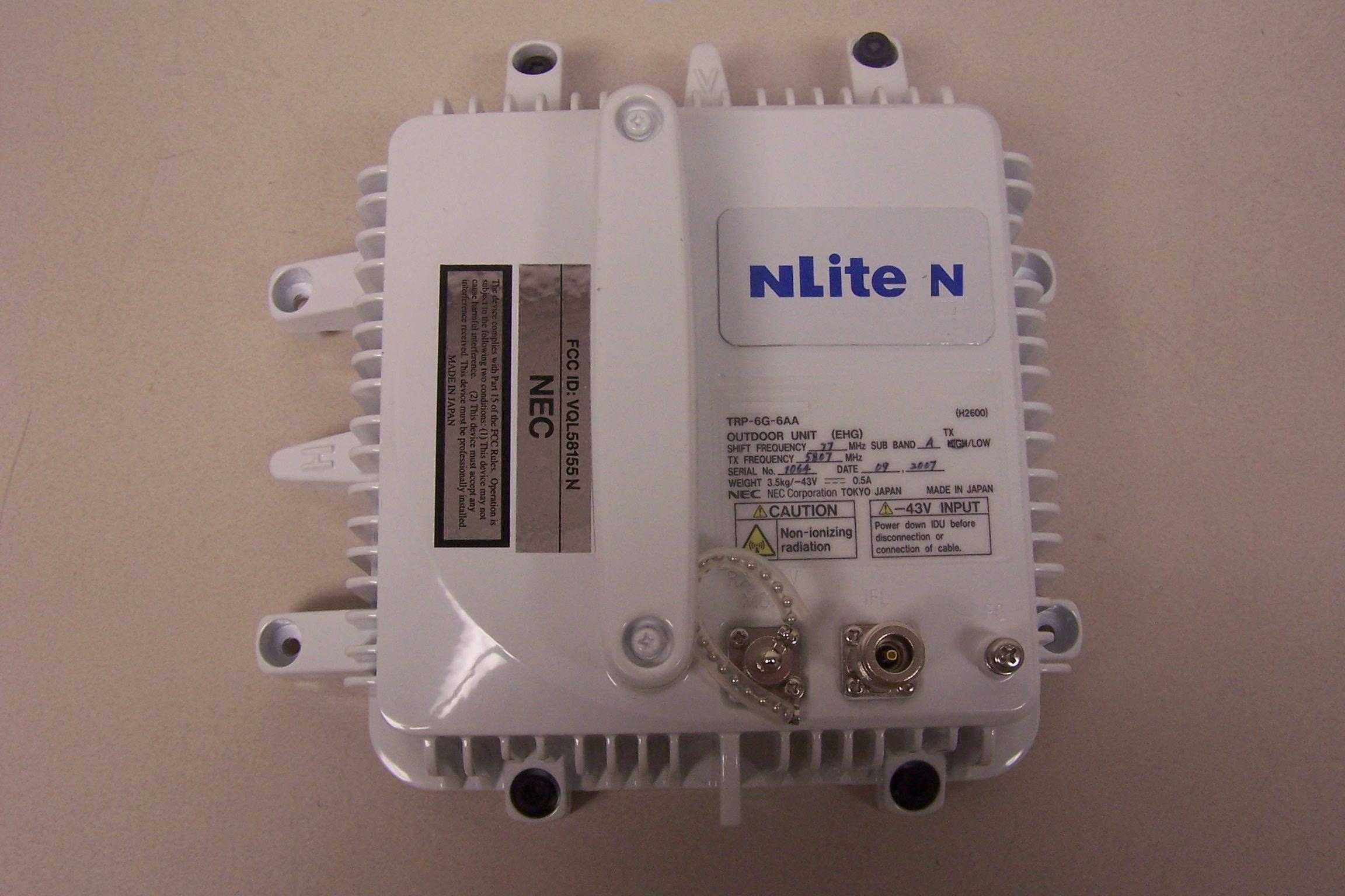
Click to zoom
Application Details
- Equipment Class
- DTS - Digital Transmission System
- Date of Grant
- Apr 08, 2010
- Application Purpose
- Original Equipment
- Date of Application
- Apr 08, 2010
- Equipment Note
- NLite N 5.8 GHz Digital Microwave Radio
- Frequency Range
- 5741.00000000 - 5834.00000000
- Company
- NEC Corporation of America
- Country
- United States
Documents & Files
Document Text
Text extracted from the exhibit documents filed with the FCC. Open a document above to read the original.
Users Manual
6-38 GHz Digital Radio System NLite N Safety Information Preface Abbreviations Instruction Manual I.Description Radio Frequency Plan for NLite N II.Operation III.Installation and Initial Line Up IV.Maintenance Appendix: LCT Operation LAN INTERFACE (10/100BASE-T(x)) Application and Setting Contents ROI-S07042 CL-2 Special User Information for Part 15 Devices: The user is cautioned that any changes / modifications not approved by the responsible party could void the user’s authority to operate the equipment. Statement for all intentional and unintentional radiators. Changes or modifications not expressly approved by the party responsible for compliance could void the user’s authority to operate the equipment. NOTE: This equipment has been tested and found to comply with the limits for a Class A digital device, pursuant to part 15 of the FCC Rules. These limits are designed to provide reasonable protection against harmful interference when the equipment is operated in a commercial environment. This equipment generates, uses, and can radiate radio frequency energy and, if not installed and used in accordance with the instruction manual, may cause harmful interference to radio communications. Operation of this equipment in a residential area is likely to cause harmful interference in which case the user will be required to correct the interference at his own expense. NOTE: The antennas used for this transmitter must be installed to provide a separation distance of at least 147 cm from all persons and must not be located or operating in conjunction with any other antenna or transmitter.
Users Manual
J101¤Ï¥·¡¼¥ë¥É¥±¡¼¥¹³°¤ÇÎɤ¤RX IF IN 51 QDEM 22 BUTTERWORTH 3RD BT=2.52(FS=24.448M) IF AMP2 51 51 INPUT/OUTPUT IMPEDANCE 50¦ ̧ INPUT/OUTPUT IMPEDANCE 50¦ ̧ (-15 TO 0DBM) 0.68 #11,12,13 #9,10 INPUT/OUTPUT IMPEDANCE 50¦ ̧ 0.12 22 FS=42M,48M¤Ï¡¢BPF¥¹¥ë¡¼ DEM BPF 0.33 100 RX IF 1.08V IF AGC 0 TO 3.3V 1.64V 28.6MA 3.28V 0.0246W CONT 0V TO 1V GAIN 1000 >1.6V 10000 100 1=LB OUTPUT RF-ON VC1 VC2 24M°Ê²¼ OUT1 0 142M°Ê¾å OUT2 1 0 OUTPUT RF-ON VC1 VC2 24M°Ê²¼ OUT1 0 142M°Ê¾å OUT2 1 0 0=LB 1=LB LB OUT 0=LB HLLB OLBCNTP OLBCNTN AMP->ATTDVGA 0 1 OUT1VC1 VC2 RF-ON L H NORM ATT=5.2DB VCC-0.78V ¥·¡¼¥ë¥É¥±¡¼¥¹ROOM2Æâ IF AMP1 10000 0V TO 1V 1000 THROUGH_HOLE 0.0246W 0-1.5V 0.33 G=15.5DB J102¤Ï¥·¡¼¥ë¥É¥±¡¼¥¹³°¤ÇÎɤ¤ 0-3.28V REGULATE 1 0 OUT2 H> 2.0V #22,23 IN VC1VC2 OUT1 OUT2 GND VPSO VPSI OCOM ICOM ENBLGAIN INPT MODEHPFLDETIDECL1DECL2DECL3 DETOOUTPEPAD ENBLGAIN INPT MODEHPFLDETIDECL1DECL2DECL3 DETOOUTPEPAD VPSO VPSI OCOM ICOM +- +- IFI GND L IFO VS BIAS V+ V- V+ V- K REF A IN VC1VC2 OUT1 OUT2GND 2XLORF+RF-EN IOUT+IOUT- QOUT+QOUT-EXPAD VCC GND GNDRF 1 #GH3#GH2#GH1 INPUT OUTPUT GNDVCC IN VC1VC2 OUT1 OUT2GND VCCGND EP 1 #GH3#GH2#GH1 IN VC1VC2 OUT1 OUT2GND RF_INB0B1B2B3B4 ATTNOUT AMPIN IBIAS ISET RF_OUT NSMODEM NWZ-029706-004 14 1 modem Jun. 15, 2009 2 1 R160 21 R111 21 R112 21 R161 21 R162 2 1 L3139 2 1 L3133 2 1 R142 2 1 R141 21 C157 21 C156 2 1 L111 21 R159 21 R158 21 R144 21 R143 2 1 R173 2 1 R172 2 1 R171 2 1 R170 21 R3103 2 1 R3102 21 R3101 2 1 R129 21 L171 21 L130 21 L108 2 1 R121 2 1 C169 2 1 C168 2 1 C167 2 1 C164 2 1 C163 21 C200 2 1 R136 2 1 R137 2 1 C135 21R164 2 1 R163 21R168 2 1 C139 2 1 C154 2 1 C155 2 1 C143 21R165 2 1 C137 2 1 C205 21R166 2 1 R167 2 1 C136 21 L110 6 5 3 2 IC107 4 1 IC107 2 1 L113 2 1 C142 2 1 C140 21 C243 2 1 C197 2 1 C196 12 8 7 6 4 1 11 9 IC108 21 C210 21 C211 23 14131615 GH1 5 10 IC108 21 R156 21 R157 21 R146 21 R145 21 C127 3 1 2 IC105 7 4 IC109 2 1 R101 2 1 C124 PN C138 21 R140 21 R118 21 R119 7 4 IC110 21 R151 21 R120 21 R113 1 TH102 21 R138 8 6 5 1 32 IC109 2 1 R116 21 R110 21 C123 2 1 R102 2 1 R105 2 1 R109 PN C126 6 32 IC110 2 1 R114 1 TH101 21R115 10 9 23 22 13 12 11 7 6 20 18 17 16 IC104 21 C114 21 C115 21 C108 21 C104 21 C129 21 C130 8 21 19 3 1 GH1 24 2 5 1514 4 IC104 21 C118 2 1 C107 PN C121 21 C119 21 C116 21 C117 21 C128 2 1 L114 21R122 21 C178 21 C239 21 C170 21 C174 21 C173 8 21 19 3 1 GH1 24 2 5 1514 4 IC106 21 C122 10 9 23 22 13 12 11 7 6 20 18 17 16 IC106 21 C179 21 C111 21 C131 PN C193 21 C182 21 C183 2 1 L140 21 C198 21 C3107 21 C3101 21 C3108 21 C3102 21 L124 2 1 C158 46 3 1 5 2 IC3101 2 1 C3103 21 C233 21 C234 21 C235 21 C237 21 C236 21 C105 21 C109 21 C112 21 C110 21 C113 2 1 L109 12 3 1314 6789 10 1815 IC101 2 1 C3104 21 L170 21 C176 21 C159 2 1 L126 2 1 L129 2 1 C165 2 1 C166 21 C177 21 C171 2 1 C3106 21R132 2 1 R130 21R134 2 1 C175 21 C103 21 R108 21 R107 21 R106 21 C132 21 L119 2 1 C3111 2 1 C125 46 3 1 5 2 IC3103 2 1 C102 21 R199 GH3GH2GH1 1 J101 21 C3110 21 C3109 2 1 C146 2 1 C145 21 C153 21 C152 46 3 1 5 2 IC102 21 R200 GH3GH2GH1 1 J102 46 3 1 5 2 IC3102 2 1 C147 6 54 1 2 3 IC111 21 L115 2 1 L116 2 1 C150 2 1 C149 2 1 C148 21 C133 21 C134 11 2 1 20 19 17 16 5 4 GH1 IC101 21 C141 21 C144 GND CKC03R1E103K NO_ASSY=TRUE UPC2708TB-E3-A CKC03R1E103K NO_ASSY=TRUE NO_ASSY=TRUE RM73H1J181FT RM73Z1JR00T CKC03R1E103K CKC03R1E103K LT5517EUF#TRPBF RES220 RES220 GND NO_ASSY=TRUE GND GNDGND OLBCNTN NO_ASSY=TRUE LQW18AN12NG00D CKC03R1A104K MAX2027EUP+T XP5V_DEM CKC03R1A104K RM73Z1JR00T GRM1552C1H390FZ01D RM73H1J511FT CKC03R1A104K RM73Z1JR00T H.FL-R-SMT CKC03R1A104K RM73H1J681FT NO_ASSY=TRUE QOUT_N RM73H1J681FT GND RM73H1J681FT RM73H1J331FT GND RM73H1J681FT RM73H1J331FT CKC18B1C225K NO_ASSY=TRUE QOUT_P RM73H1J123FT NO_ASSY=TRUE RM73H1J331FTRM73H1J331FT CKC18B1C225K NO_ASSY=TRUENO_ASSY=TRUE CKC18B1C225K GND GND RM73H1J511FT GND RM73H1J100FT GND GND GRM1552C1H150FZ01D GRM1552C1H150FZ01D GND NO_ASSY=TRUE RM73Z1JR00T RM73Z1JR00T NO_ASSY=TRUE LQW18AN39NG00D GND CKC03R1E103K CKC03X7R1H102K TEESVA1C106M8R GND TPD GND GND ORXCBL0 RM73H1J123FT IOUT_P XP5V_DEMXP5V_DEM GND CKC03R1E103K GND +5V RM73Z1JR00T ORXCBL1 IFLOOPBACK OLBCNTP OBPFSELBOBPFSEL OBPFSEL GND XP5V_DEM +5V GND GND GND +5V GND GND GNDGND CKC03R1E103K GND H_FL_R_SMT GND GNDGNDGNDGND UPG2214TB-E4-A GNDGND GND GND GND GRM1552C1H390FZ01D LQW18ANR22G00D GND GND GND UPG2214TB-E4-A GND GNDGND CKC03R1E103K CKC03R1E103K GND GND OLBCNTP CKC03R1E103K GND CKC03R1A104K GND GND GND GND LQH32CN1R0M23L XP5V_DEM GND GND GND +5V GND GND GND GND +5V GND GND GND N_280M_SPXOPON PON R139_1_C106_2 XP3R3V_REG1 RM73H1J103FT CKC03R1E103K GND RM73H1J273FT GND AD8061ARZ-REEL7 GND XP5V_DEM RM73H1J471FTRM73H1J152FT GND GND CKC03R1A104K GND TLV3501AIDR TLV3501AIDR RM73H1J392FT GND TEESVA1C106M8R UPC1093T-E1-AZ GND VOLTAGE=+3.3 OIFAGCD GND RM73H1J121FT CKC03R1A104K OLBCNTN OBPFSELB XP5V_DEM RM73H1J123FT CKC03R1E103K CKC03X7R1H102K GND GND H_FL_R_SMT RM73Z1JR00T GND RM73H1J123FT NO_ASSY=TRUE IOUT_N NO_ASSY=TRUE CKC18B1C225K ORXCBL4ORXCBL3 AD8368ACPZ-REEL7 GRM1552C1H120FZ01D RM73H1J223FT GND AD8061ARZ-REEL7 LT5517EUF#TRPBF GND +5V NO_ASSY=TRUE GRM1552C1H120FZ01D LQW18AN56NG00D LQW18AN47NG00D H.FL-R-SMT NO_ASSY=TRUE AD8368ACPZ-REEL7 NO_ASSY=TRUE AD8368ACPZ-REEL7 IC106_24 XP5V_DEM CKC03R1A104K CKC03R1E103K LQW18AN47NG00D GND NO_ASSY=TRUE GND CKC03R1E103K UPG2214TB-E4-A NO_ASSY=TRUE UPG2214TB-E4-A MAX2027EUP+T GND ORXCBL2 CKC03R1A104K XP5V_DEM CKC03R1E103K GND NO_ASSY=TRUE GND RM73H1J103FT GND GND LQW18AN LQW18AN47NG00D THS9000DRWR LQW18AN22NG00D LQW18AN RX_IF 11D8 6A6 4B10 1B4 2F12E1 11D3 2C1 11E3 4C11 11D8 6B6 4B10 1B5 11E5 5C10 5B5 1B11 11D5 5C10 5B5 1B11 11D5 5C10 5B5 1B6 11D8 6B6 4B10 1B4 6C8 3C5 12B11 1C2 7E4 12B11 1E9 11F3 11D8 6A6 4B10 1B5 11E5 5C10 5B5 1B6 2D1 11E311E311E3 7B5 IC102_8_C158_2 CKC03R1A104K NO_ASSY=TRUE GRM1552C1H120FZ01D LQW18AN27NG00D CKC03R1A104K NO_ASSY=TRUE RM73H1J181FT NO_ASSY=TRUE GJM1552C1H100FB01D NO_ASSY=TRUE XP5V_DEM GND NLV25T-1R0J-PF NO_ASSY=TRUE GND NO_ASSY=TRUE NO_ASSY=TRUE CKC03R1E103K CKC03R1E103K GJM155…
Text truncated - open the document above for the full version.
Users Manual
ROI-S07045-051ECONTENTS July, 2009 CL-1 NLite N 6-38 GHz DIGITAL RADIO SYSTEM Section III INSTALLATION AND INITIAL LINE UP CONTENTS TITLEPAGE 1GENERAL ••••••••••••••••••••••••••••••••••••••••••••••••••••••••••••• 1-1 2INSTALLATION •••••••••••••••••••••••••••••••••••••••••••••••••••••• 2-1 2.1Packages••••••••••••••••••••••••••••••••••••••••••••••••••••••••••• 2-2 2.2Unpacking of MDP and TRP •••••••••••••••••••••••••••••••••• 2-9 2.3MDP Mounting••••••••••••••••••••••••••••••••••••••••••••••••••• 2-13 2.4DC-DC CONV UNIT Mounting (Optional) ••••••••••••••••• 2-16 2.5TRP Mounting ••••••••••••••••••••••••••••••••••••••••••••••••••• 2-17 2.5.1Mounting •••••••••••••••••••••••••••••••••••••••••••••••••••••••••• 2-19 2.5.2TRP Wall Mounting••••••••••••••••••••••••••••••••••••••••••••• 2-70 2.5.3TRP Rack Mounting•••••••••••••••••••••••••••••••••••••••••••• 2-74 2.6Feeder Connection ••••••••••••••••••••••••••••••••••••••••••••• 2-76 2.7Cable Termination •••••••••••••••••••••••••••••••••••••••••••••• 2-94 2.8Wiring and Forming•••••••••••••••••••••••••••••••••••••••••• 2-127 2.9Frame Grounding••••••••••••••••••••••••••••••••••••••••••••• 2-131 2.10Waterproof Protection••••••••••••••••••••••••••••••••••••••• 2-134 3INITIAL LINE UP ••••••••••••••••••••••••••••••••••••••••••••••••••••• 3-1 3.1Start-up••••••••••••••••••••••••••••••••••••••••••••••••••••••••••••• 3-2 3.2Shut-down ••••••••••••••••••••••••••••••••••••••••••••••••••••••••• 3-8 3.3Initial Setting •••••••••••••••••••••••••••••••••••••••••••••••••••••• 3-9 3.3.1Equipment Setup ••••••••••••••••••••••••••••••••••••••••••••••• 3-10 3.3.2Provisioning ••••••••••••••••••••••••••••••••••••••••••••••••••••• 3-11 3.4Antenna Orientation ••••••••••••••••••••••••••••••••••••••••••• 3-12 3.5Lineup Test••••••••••••••••••••••••••••••••••••••••••••••••••••••• 3-26 3.6TRP Mounting/Demounting (ALL INDOOR TRP) ••••••• 3-33 3.6.1TRP Demounting (ALL INDOOR TRP)••••••••••••••••••••• 3-41 3.7System Expansion (ALL INDOOR TRP) •••••••••••••••••• 3-43 CONTENTSROI-S07045 CL-2 2 pages (This page is intentionally left blank.) ROI-S07045GENERAL 1-1 1. GENERAL This section provides installation and initial line up information on the NLite N used for 6-38 GHz microwave radio system. GENERALROI-S07045 1-2 2 pages (This page is intentionally left blank.) ROI-S07045INSTALLATION 2-1 2. INSTALLATION The standard installation is summarized in this section. Included herein is information on typical installation work flow and guides for MDP installation, TRP installation, Antenna (ANT) installation, waveguide connection and coaxial cable connections. The installation flow diagram is shown below. This product is a part of radio link system, and is intended to be connected with a external antenna. This product will be installed and operated by professional. After installation, the professional person shall make sure that the system shall comply with the relevant limits for general public exposure specified as basic restrictions or reference levels in the council Recommendation 1999/519/EC. Fig. 2-1 Typical Installation Flow Diagram Unpacking of MDP (see para 2.2) Unpacking of TRP (see para 2.2) TRP Mounting (see para 2.5) MDP Mounting (see para 2.3) Feeder Connection (see para 2.6) Frame Grounding (see para 2.9) Cable Termination (see para 2.7) Waterproof Protection (see para 2.10) INSTALLATIONROI-S07045 2-2 2.1 Packages Each unpacked component of the [ ] GHz [ ] MB digital radio system must be checked as shown below. CONTENS LISTDRAWING NO. MDP and TRPFig. 2-2 Mounting BracketFig. 2-4 Installation KitFig. 2-5 and Fig. 2-7 ROI-S07045INSTALLATION 2-3 Notes:*1One more TRP and MODEM module are provided for HS/ Twinpath configuration. *2One spare fuse is provided in the MODEM module. *3TRP NHG Type: 6-38 GHz, TRP NHG2 Type: 6-8GHz/13- 38 HGz, TRP Mx Type: 52 GHz Fig. 2-2 Contents of Basic Unit Package 3 1 2 4 5 6 7 (*1) SELV ! AUX/ALM LCTNMS NE SC IN/OUT EOW PROTECT CALL MMC MAINT MEMORY MDP XIF IN XIF OUT IF IN/OUT TX RX RESET XPIC CTRL XPIC PWR TRP MD/ CBL PWR PULL G G ALM 100M PORT 1PORT 2 100M Ns Ns DS1 IN/OUT WS IN/OUT N (*1) No.DESCRIPTION 1 TRP-( )G-1B (NHG)/ TRP-( )G-5B (NHG2)/ TRP-6G-6AA (EHG)/ TRP-24G-2B*3 2MDP-150MB-3AA (MDP) 3O-Ring (Attached to the waveguide type TRP) 4 Power Connector (Molex Housing M5557-4R ( ×1ea) and Socket Contact (5556TL ( × 4 each)) 5Cylindrical Fuse ((RKS-F91000-0107) (6.3A) ( ×1ea) *2) 6XPIC CTRL Cable (×1) (apply for XPIC configuration only) 7X-IF Coaxial Cable (×2) (apply for XPIC configuration only) INSTALLATIONROI-S07045 2-4 Fig. 2-3 Contents of Optional Unit Package Νοte:√: Usable *1: TRP (NHP type) can not be used with DC-DC CONV. *2: ALL INDOOR TRP can not be used with NWA-0011060-001 (24/ 48V type). SELV PWR PULL PWR ALM FUSE (250V/8AH) − 43V G OUT STD G SELV PWR PULL PWR ALM FUSE (250V/8AH) − 43V G OUT STD G NWA-011060-001 DC-DC CONV UNIT SER No. DATE , WEIGHT 2.5kg MADE IN JAPAN NEC Corporation TOKYO JAPAN 1+0 System STD Input : 20 60V 3.4A 1.0A Output : − 43V 1.3A 1+1 System STD Input : 20 60V 1.3A×2 3.4A 1.0A ×2 Output : − 43V 1 No.DESCRIPTION 1NWA-011060-[ ] DC-DC CONV UNIT (see Fig. 2-7 for details) DC-DC CONV UNITNHG/NHG2/EHGNHPALL INDOOR TRP NWA-0011060-001 (24/48V type) √*1*2 NWA-011060-002 (48V type) √ *1 √ NWA-011060-003 (24V type) √ *1 √ ROI-S07045INSTALLATION 2-5 Fig. 2-4 Pole Mounting Bracket (Supplied with Antenna) 3 21 4 No.DESCRIPTION 1Pole Mounting Bracket for Coaxial Cable (6 GHz)/Waveguide Connection Type 2Pole Mounting Bracket for Coaxial Cable Connection Type (6 GHz) 3Pole Mounting Bracket for Wave Guide connection Type 4Pole Mounting Bracket for Antenna direct Mounting Type INSTALLATIONROI-S07045 2-6 SELV ! AUX/ALM LCT NMS NE SC IN/OUT EOW PROTECT CALL MMC MAINT MEMORY MDP XIF IN XIF OUT IF IN/OUT TX RX RESET XPIC CTRL XPIC PWR TRP MD/ CBL PWR PULL G G Ns N 100M PORT 3 PORT4 100M ALM DS1 IN/OUT WS IN/OUT Ns Fig. 2-5 Installation Kit Packing List of MDP and TRP for 1+0 System MDP No.1 TRP MOLEX CONNECTOR/ (FEMALE) LUG D-SUB…
Text truncated - open the document above for the full version.
Users Manual
ROI-S07046-051ECONTENTS July, 2009 CL-1 NLite N 6-38 GHz DIGITAL RADIO SYSTEM Section IV MAINTENANCE CONTENTS TITLEPAGE 1GENERAL ••••••••••••••••••••••••••••••••••••••••••••••••••••••••••••• 1-1 2PRECAUTIONS •••••••••••••••••••••••••••••••••••••••••••••••••••••• 2-1 3TEST SETS AND ACCESSORIES ••••••••••••••••••••••••••••••• 3-1 4ROUTINE MAINTENANCE •••••••••••••••••••••••••••••••••••••••• 4-1 4.1Meter Reading ••••••••••••••••••••••••••••••••••••••••••••••••••• 4-1 4.2Performance Monitoring•••••••••••••••••••••••••••••••••••••• 4-2 5CORRECTIVE MAINTENANCE •••••••••••••••••••••••••••••••••• 5-1 5.1Alarm/Status ••••••••••••••••••••••••••••••••••••••••••••••••••••• 5-1 5.1.1Alarm and Status ••••••••••••••••••••••••••••••••••••••••••••••• 5-2 5.1.2Control Item •••••••••••••••••••••••••••••••••••••••••••••••••••••• 5-8 5.1.3Loopback •••••••••••••••••••••••••••••••••••••••••••••••••••••••• 5-10 5.1.4In-band Loopback ••••••••••••••••••••••••••••••••••••••••••••• 5-15 5.1.5BER Measurement •••••••••••••••••••••••••••••••••••••••••••• 5-22 5.1.6Trouble Shooting Flow••••••••••••••••••••••••••••••••••••••• 5-23 5.2Replacement •••••••••••••••••••••••••••••••••••••••••••••••••••• 5-28 5.2.1TRP Replacement ••••••••••••••••••••••••••••••••••••••••••••• 5-28 5.2.2MDP and Module Replacement •••••••••••••••••••••••••••• 5-34 5.2.3ALL INDOOR TRP Replacement ••••••••••••••••••••••••••• 5-47 5.2.4Fuse Replacement •••••••••••••••••••••••••••••••••••••••••••• 5-50 CONTENTSROI-S07046 CL-2 2 pages (This page is intentionally left blank.) ROI-S07046GENERAL 1-1 1. GENERAL This section provides instructions for maintenance of the NLite N used for 6-38 GHz microwave radio system. This section provides instructions on the precautions, test setup and accessories, routine maintenance, corrective maintenance and mounting of optional modules. GENERALROI-S07046 1-2 2 pages (This page is intentionally left blank.) ROI-S07046PRECAUTIONS 2-1 2. PRECAUTIONS The following precautions must be carefully observed during maintenance. (a) The maintenance personnel should report arrival and departure from a station to the relevant station. The following are dangers and warnings to the maintenance personnel. Warning: 1. The –48 V DC power is superimposed on the centre conductor of the coaxial cable between the MDP and the TRP/ALL INDOOR TRP. Connecting test equipment directly to this terminal may damage it and touching the coaxial cable core may cause electrical shock. 2. Persons performing maintenance must take necessary steps to avoid Electro-static Discharge (ESD) which may damage the modules on the MDP or cause error. Wear a conductive wrist strap connected to the grounded (G) jack on the front of the equipment shelf. This will minimize static build-up during maintenance. (see Fig. 2-1). 3. Do not remove/connect the IF cable with the MDP power ON. Turn the MDP power OFF before connecting/ disconnecting the IF cable, or equipment may be damaged. 4. After turning ON the equipment, wait at least 1 minute before turning it OFF again. Repeatedly turning the power ON and OFF within a short interval may cause the MDP to fail. 5. Do not allow open or short circuit of TRP/ALL INDOOR TRP TX output with the TX power on conditions. Perform the TX Mute control in the Maintenance mode or turn the PWR switch off at the MDP before disconnecting cable or feeder from the TRP/ALL INDOOR TRP TX output. 6. Contact NEC before program download on the LCT is performed. Equipment may not function correctly with improper operation. Caution: 1. The top surface of the MDP above MODEM is hot in operation. 2. When replacing the MODEM, 2P LAN INTFC or DC- DC CONV (optional) turn off the PWR switch and disconnect all cables connected to the module which is to be replaced. PRECAUTIONSROI-S07046 2-2 (b) During maintenance, the MDP should be set to Maintenance “On” condition by the local craft terminal (LCT). (c) To avoid traffic interruption, under the maintenance, perform TX/ RX SW manual switching in 1+1 system. Note: When TX/RX SW has been automatically switched during a fault, keep this condition by manual switching operation. (d) While the CPU is initialized by the CPU RESET switch, alarm(s) status is reset to normal. After initialization, the alarm information is properly provided through relay contacts. (e) Information on the maintenance and the control such as Mute, CW, LB, etc. is released if the power is turned off. (f)If each setup item of “Equipment Setup” or “Provisioning” is changed during in operation, traffic will be momentarily interrupted. (g) When the TX SW is activated, momentary traffic interruption may occurs. (h) Before removing or installing the MDP/TRP, turn off the power switch on the MODEM. (i)After completing maintenance, restore all connections, manual control settings to normal and confirm that all alarm LEDs are unlit. (j)When replacing the MODEM or 2P LAN INTFC with spare, disconnect every cables connected to the module which is to be replaced, then turn off the power switch on the MODEM, surely. (k) After equipment start-up, allow the equipment to warm up at least 30 minutes. ROI-S07046PRECAUTIONS 2-3 Caution Tighten the TNC-male connector of IF cable to the MDP with engage connector nut only using fingers and holding the cable with another hand. Tighten the engage connector nut only for the L-angle connector also. (Tightening Torque : 0.3 to 0.5 N •m (3 to 5kg •cm)) MDP MDP IF CABLE IF CABLE MDP IF CABLE Straight Type L-Angle Type L Angle Type If rotate other parts of the L-angle connector as illustrated left, it can cause connector damage. PRECAUTIONSROI-S07046 2-4 Chart 2-1 Wrist Strap Connection StepProcedure 1Connect the wrist strap to the ESD ground terminal (G). Fig. 2-1 ESD Ground Terminal Location Fig. 2-2 Location of G Terminal (TRP) 1+0 SYSTEM 1+1 SYSTEM MDP G G (Blank) MDP SELV ! AUX/ALM LCTNMS NE SC IN/OUT EOW PROTECT CALL MMC MAINT MEMORY MDP XIF IN XIF OUT IF IN/OUT TX RX RESET XPIC CTRL XPIC PWR TRP MD/ CBL PWR PULL …
Text truncated - open the document above for the full version.
Users Manual
ROI-S07047-051ECONTENTS July, 2009 CL-1 NLite N 6-38GHz DIGITAL RADIO SYSTEM Section IV APPENDIX NLite N LCT OPERATION CONTENTS TITLEPAGE 1INTRODUCTION . . . . . . . . . . . . . . . . . . . . . . . . . . . . . . . . . . . . 1 1.1Accessing the NLite N . . . . . . . . . . . . . . . . . . . . . . . . . . . . 2 1.2LCT Menu Items. . . . . . . . . . . . . . . . . . . . . . . . . . . . . . . . . . 9 2ALARM/STATUS . . . . . . . . . . . . . . . . . . . . . . . . . . . . . . . . . . 10 2.1Alarm Status . . . . . . . . . . . . . . . . . . . . . . . . . . . . . . . . . . . 10 3EQUIPMENT SETUP . . . . . . . . . . . . . . . . . . . . . . . . . . . . . . . 19 3.1Equipment Setup. . . . . . . . . . . . . . . . . . . . . . . . . . . . . . . . 20 4INVENTORY . . . . . . . . . . . . . . . . . . . . . . . . . . . . . . . . . . . . . . 28 5AUX. I/O . . . . . . . . . . . . . . . . . . . . . . . . . . . . . . . . . . . . . . . . . 29 6MAINTENANCE . . . . . . . . . . . . . . . . . . . . . . . . . . . . . . . . . . . 30 6.1Maintenance1. . . . . . . . . . . . . . . . . . . . . . . . . . . . . . . . . . . 31 6.2Maintenance2. . . . . . . . . . . . . . . . . . . . . . . . . . . . . . . . . . . 39 7PROVISIONING . . . . . . . . . . . . . . . . . . . . . . . . . . . . . . . . . . . 46 7.1Provisioning Setup . . . . . . . . . . . . . . . . . . . . . . . . . . . . . . 47 8METERING . . . . . . . . . . . . . . . . . . . . . . . . . . . . . . . . . . . . . . . 66 9PMON . . . . . . . . . . . . . . . . . . . . . . . . . . . . . . . . . . . . . . . . . . . 67 9.1PMON . . . . . . . . . . . . . . . . . . . . . . . . . . . . . . . . . . . . . . . . . 67 9.1.1PMON (History) . . . . . . . . . . . . . . . . . . . . . . . . . . . . . . . . . 67 9.1.2RMON (History) . . . . . . . . . . . . . . . . . . . . . . . . . . . . . . . . . 70 10INSTALLATION OF USB . . . . . . . . . . . . . . . . . . . . . . . . . . . . 74 11DIAL-UP SETTING . . . . . . . . . . . . . . . . . . . . . . . . . . . . . . . . . 77 12LCT INSTALLATION . . . . . . . . . . . . . . . . . . . . . . . . . . . . . . . 86 13FIREWALL SETUP FOR WINDOWS VISTA . . . . . . . . . . . . . 95 13.1Firewall Setup . . . . . . . . . . . . . . . . . . . . . . . . . . . . . . . . . . 95 13.2Firewall Setup (with Advanced Security) . . . . . . . . . . . . 98 CONTENTSROI-S07047 CL-2 2 pages (This page is intentionally left blank.) ROI-S07047INTRODUCTION -1- 1.INTRODUCTION This Local Craft Terminal (LCT) Operation Manual describe how to setup, manage, monitor and controls NLite N microwave radio systems. User should prepare the computer (PC), USB cable and necessary peripheral device used for equipment setup. The following hardware and software for the PC are recommended. Use the latest updated version of the software. Hardware requirement • HD:100 MB or higher free capacity •RAM:512 MB • Display:LCD 1,024 × 768 •CD-ROM drive • Serial port •USB port • USB cable with USB-B connector Software requirement (English version) • OS: Windows 2000/XP/Vista INTRODUCTIONROI-S07047 -2- 1.1 Accessing the NLite N This section explains the LCT connections and Startup Method (Procedure) LCT software should be first installed in the PC from the supplied CD- ROM, referring to installation procedure in the chapters 10 to 12. 1Connect the Computer (PC) with a USB cable between the LCT port and the USB port. NLite N MDP USB Driver USB Driver LCT Setup File LCT Application Note: For the LCT Application Rev. 2.01.xxx, LCT Application setup_LCT_NLite_N_rev_ 2_xx_xxx_Full.exe execute the installation with the”setup_LCT_NLite_N_rev_2_xx_xxx_Full.exe”. SELV ! AUX/ALM LCTNMS NE SC IN/OUT EOW PROTECT CALL MMC MAINT MEMORY MDP XIF IN XIF OUT IF IN/OUT TX RX RESET XPIC CTRL XPIC PWR TRP MD/ CBL PWR PULL G SELV ! XIF IN XIF OUT IF IN/OUT TX RX RESET XPIC CTRL XPIC PWR TRP MD/ CBL PWR PULL G G ALM 100M PORT 1PORT 2 100M Ns Ns WS IN/OUT Ns N DS1 IN/OUT ROI-S07047INTRODUCTION -3- Notes: USB modem driver should be installed first before creating the dial-up connection. 2Click on the “START” menu button, select “Settings”, “Network Connections”, “LCT”, then, “Connect LCT” dial-up dialog is appeared. USB Cable PC for LCT USB port NLite N MDP LCTNMS NE NLite N TRP LCT port LCT SETUP *Use the typical USB shielded cable. (Do not use the un-shielded cable ) SELV ! AUX/ALM SC IN/OUT EOW PROTECT CALL MMC MAINT MEMORY MDP XIF IN XIF OUT IF IN/OUT TX RX RESET XPIC CTRL XPIC PWR TRP MD/ CBL PWR PULL G SELV ! XIF IN XIF OUT IF IN/OUT TX RX RESET XPIC CTRL XPIC PWR TRP MD/ CBL PWR PULL G G ALM 100M PORT 1PORT 2 100M Ns Ns WS IN/OUT Ns N DS1 IN/OUT LCTNMS NE INTRODUCTIONROI-S07047 -4- 3The dialog box “Connect LCT” appears. 4Click on the “Dial” button, then the PC is connected to the MDP. ROI-S07047INTRODUCTION -5- Note: There is a possibility that the USB connection is dropped during a long-duration operation depending on the device type of computer. In the case of a connection failure, please reconnect the dial-up connection. 6Enter User ID and password in User/Password entry fields and press the “Login” button. 5Double click on the short-cut icon or select the “Programs” → “NEC_ LCT” → “LCT For NLite N” from the “start” menu. INTRODUCTIONROI-S07047 -6- Default password of Admin is defined as “12345678” The password can be changed by Administrator privilege. The LCT operator must have the security system privilege to control of NLite N systems. (The password change is described in Chapter 6.2 Maintenance 2) 7Following LCT Open View is displayed. (Cascaded Alarm/Status items are displayed in Main area by default.) User IDPass WordPrivilege Admin******** Access to the LCT and control User(non password) Access to the LCT (monitor only) NLite N LCT Open View (Example) ROI-S07047INTRODUCTION -7- Symbols in the Open View are described as follows. Description of the LCT Menu Conventions LCT Menu “Set” button appears/disappears depending on the Menu item selected in the “LCT Menu”. Main area Menu area Common area Alarm Status Equipment Setup Inventory AU…
Text truncated - open the document above for the full version.
Users Manual
NLite NAPPENDIX ROI-S07048-051E July, 2009 Contents -i- APPENDIX (NLite N) LAN INTERFACE (10/100BASE-T(x)) Application and Setting 1. OUTLINE.............................................................................................................A-1 2. MODULE INFORMATION..................................................................................A-2 3. APPLICATION EXAMPLE.................................................................................A-3 4. SETUP OF THE MODULE..................................................................................A-6 4.1Setup of LAN Mode (LAN Port Usage).................................................................. A-7 4.1.1Multiplexing Signal ................................................................................................. A-7 4.1.2Multiplexing Mode .................................................................................................. A-8 4.1.3Setup of LAN Port Usage........................................................................................ A-9 4.2Setup of LAN Signal Bandwidth (LAN Capacity)................................................ A-10 4.2.1Setup of LAN Capacity ......................................................................................... A-11 4.3Setup of the Switching Mode (Switching Function) ............................................. A-14 4.4Setup of 1.5M Framing.......................................................................................... A-14 4.5Setup of Used/Unused Port (Port Usage) .............................................................. A-14 4.6Setup of Port Speed & Duplex .............................................................................. A-15 4.6.1Setup for External Connection .............................................................................. A-16 4.6.2Setup of MDI / MDIX ........................................................................................... A-16 4.7Setup of Flow Control (Flow Control) .................................................................. A-17 4.7.1Flow Control.......................................................................................................... A-17 4.8Setup of Collision Report ...................................................................................... A-17 4.9Port Link Loss Forwarding (LLF) / Link Down Control ...................................... A-18 4.9.1LAN .......................................................................................................................A-18 5. ALARM/STATUS INDICATION AND REPORTING ........................................A-19 5.1LED Indication ...................................................................................................... A-20 5.2Alarm/Status Report .............................................................................................. A-21 5.3Remote Network Monitoring (RMON)................................................................. A-22 6. MAINTENANCE/CONTROL .............................................................................A-23 6.1Remote Reset (LAN Device Reset)....................................................................... A-23 APPENDIXNLite N ROI-S07048 Contents -ii- E This page is intentionally left blank. NLite NROI-S07048 APPENDIX OUTLINE A-1 1. OUTLINE On the NLite E, the LAN signal can be transported in Main signal domain and Auxiliary signal domain using adaptive LAN interface module. DATA IP Phone TV CONF DATA Router LAN Router FAX TEL PABX NLite N 10/100BASE-T(X) 10/100BASE-T(X) PDH/SONET/ATM Network IP (private) Network ROI-S07048NLite N APPENDIX MODULE INFORMATION A-2 2. MODULE INFORMATION (1)NWA-036103-001 2P LAN INTFC It provides two (2) ports 10BASE-T/100BASE-TX interface and up to 16 DS1 and one (1) WS channel (equivalent to DS1 bandwidth per channel). By easy setting, besides each port can be used independently separated, a signal domain can be shared with two (2) LAN ports. LAN through put maximum capacities can be set from 1.5 Mbps to 150 Mbps. ModuleFeatures NWA-036103-001 2P LAN INTFC • Maximum LAN through put capacities, 1.5 Mbps - 150 Mbps • 10BASE-T/100BASE-TX x 2 port • Auto Negotiation / Auto MDI/MDIX, effective • 1024 MAC Address Table, automatically learning and aging. • Maximum frame size 1548 bytes • Conformed to IEEE 802.3x, Pause Frame Flow Contr…
Text truncated - open the document above for the full version.
Contact Information
Applicant
Mark Stuart Cowles(Senior Project Planning Engineer)
Technical Contact
NEC Corporation of AmericaMark Stuart Cowles
[email protected]703-834-4174
2816 Towerview Road · Herndon, Virginia · United States
Test Firm
EUROFINS ELECTRICAL AND ELECTRONIC TESTING NA, INCGreg Kovolenko
Technical Specifications
| # | Rule Parts | Frequency Range | Power Output |
|---|---|---|---|
| 1 | 15C | 5.74 GHz - 5.83 GHz | 270.00 mW |
Other Applications from NEC Corporation of America
VQL58155TRP
Dec 06, 2012NEC iPasolink Digital Microwave Radio
Equipment Class
DTS - Digital Transmission System
VQL5845
Feb 20, 20085.8 GHz Unlicensed Digital Microwave Radio
Equipment Class
DTS - Digital Transmission System
VQL5808
Feb 20, 2008Unlicensed 5.8 GHz Point to Point Microwave Radio
Equipment Class
DTS - Digital Transmission System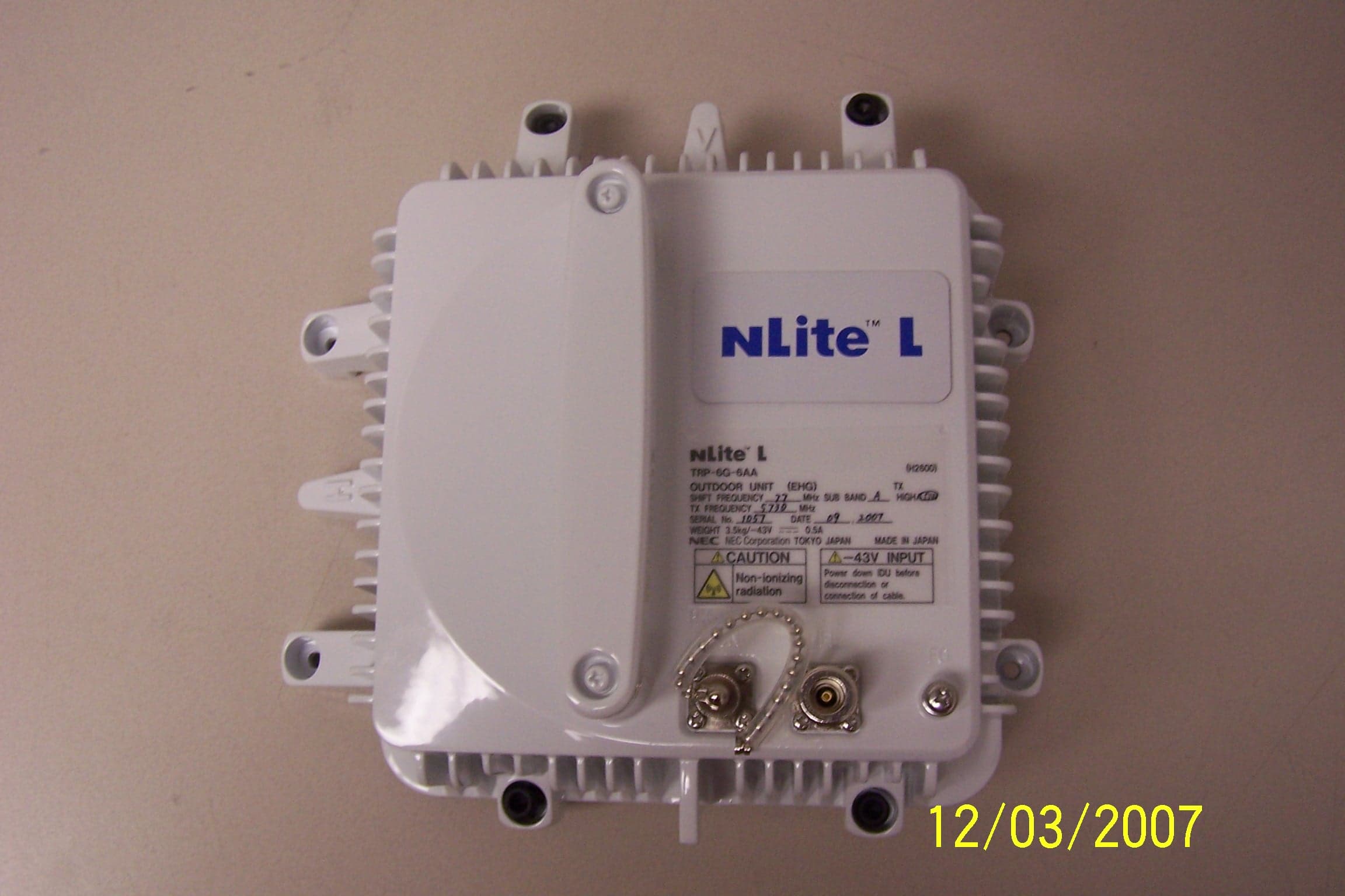
VQL5816
Feb 20, 20085.8 GHz Unlicensed Digital Microwave Radio
Equipment Class
DTS - Digital Transmission System