VQL58155TRPNEC iPasolink Digital Microwave Radio
NEC Corporation of America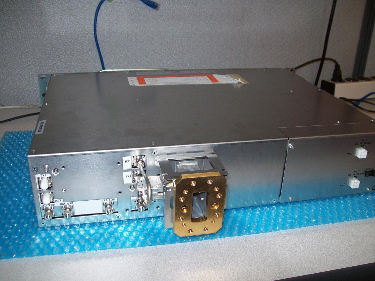
Click to zoom
Application Details
- Equipment Class
- DTS - Digital Transmission System
- Date of Grant
- Dec 06, 2012
- Application Purpose
- Original Equipment
- Date of Application
- Dec 06, 2012
- Equipment Note
- NEC iPasolink Digital Microwave Radio
- Frequency Range
- 5739.50000000 - 5816.50000000
- Company
- NEC Corporation of America
- Country
- United States
Documents & Files
Document Text
Text extracted from the exhibit documents filed with the FCC. Open a document above to read the original.
Users Manual
Document ID: 141-DOC000008-E iPasolink Installation and Commissioning Guide Release: Beta Draft Version: 0.3 Copyright Notice Copyright © 2000-2011. All rights reserved. No part of this book or manual may be reproduced or transmitted in any form or by any means, electronic or mechanical, including photocopying, recording, or by any information storage and retrieval system, without the express written permission from NEC Corporation. Warning and Disclaimer While every effort has been made to make this document as complete and as accurate as possible, NEC Corporation does not accept any responsibility for poorly designed or malfunctioning networks. The information provided in this document is on an “as is” basis and is subject to change without prior notice. The author, NEC Corporation, shall have neither liability nor responsibility to any person or entity with respect to any loss or damage arising from the information contained in this document or from the use of equipment or software that might accompany it. The opinions expressed in this document are not necessarily those of NEC Corporation. Trademark Acknowledgments All terms mentioned in this book that are known trademarks or service marks have been appropriately capitalized. All trademarks duly acknowledged. NEC Corporation cannot attest to the accuracy of third-party information. Use of a term in this document should not be regarded as affecting the validity of any trademark or service mark. Technical Support Information NEC Corporation customers can contact NEC Corporation Support Center (TSC) 24x7x365 for any assistance through helpline, fax or email. - Phone(s): +91 80 41719090, +91 80 26591082, +91 80 26591080 - Fax: +91 80 26591079 - Skype: tscsupport123 Revision History Version Date Modifications Made 0.1 24 May 2011 Alpha Draft 0.2 25 May 2011 Preliminary Draft 0.3 21 June 2011 Beta Draft Your Feedback is valuable to us! Your opinion is of great value and will help us improve the quality of our product documentation and offer better services to you. Please take few moments to provide us your opinion of this document. Your evaluation of this document Presentation: (Introductions, Procedures, Illustrations, Completeness, Level of Detail, Organization, Appearance) Good Fair Average Poor Bad N/A Intelligibility: (Language, Vocabulary, Readability and Clarity, Technical Accuracy, Content) Good Fair Average Poor Bad N/A Accessibility: (Contents, Index, Headings, Numbering, Glossary) Good Fair Average Poor Bad N/A Your suggestions for improving this document Improve the overview/introduction Make it more concise/brief Improve the Contents Add more step-by-step procedures/ tutorials Improve the organization Add more troubleshooting information Include more figures Make it less technical Add more examples Add more/better quick reference aids Add more detail Improve the index Other Suggestions: If you wish to be contacted regarding your comments, please provide your contact details: Name: Company: Postcode: Address: Telephone: Email: iv Table of Contents List of Figures vii List of Tables viii Chapter 1 Using this Guide 11 Who This Guide Is For ............................................................................................................... 11 What This Guide Covers ............................................................................................................. 11 What You Should Already Know .............................................................................................. 12 Safety Signs Conventions ............................................................................................................ 12 Typographical Conventions ........................................................................................................ 13 Mouse Operation Conventions .................................................................................................. 13 Chapter Organization ................................................................................................................... 14 Using NEC Corporation Product Documentation ................................................................. 15 Related Documents ...................................................................................................................... 16 Chapter 2 Understanding Installation, Commissioning, and Testing Process17 Installation and Commissioning Process Overview ................................................................ 18 Understanding Installation Procedure ....................................................................................... 18 Understanding Commissioning Procedure ............................................................................... 19 Chapter 3 Observing Safety Guidelines 21 Safety Standard Compliance........................................................................................................ 21 Safety Recommendations ............................................................................................................ 22 General Safety Guidelines ......................................................................................................... 22 Maintaining Safety with Electricity ............................................................................................ 22 Preventing Electrostatic Discharge Damage ................................................................................ 23 Site Environment ...................................................................................................................... 23 General Site Requirements .......................................................................................................... 23 Preventive Site Configuration ..................................................................................................... 24 Configuring Equipment Racks ................................…
Text truncated - open the document above for the full version.
Block Diagram
NEC iPasolink 5.8 GHz Indoor Block Diagram and Clock Detail 280.000 MHz 12.000 MHz 97.792 MHz 38.8800 MHz 97.792 MHz 48.896 MHz 340.000 MHz TX IF 140.000 MHz RX IF TX Signal Flow RX Signal Flow 5.8 GHz
Cover Letter(s)
November 29th, 2012 NEC Corporation of America 13872 Redskins Drive. Herndon, VA 20171 To Whom It May Concern: This purpose of this letter is to comply with Section 0.457(d)(2)(I) pertaining to confidential materials. NEC Corporation would like all the documents uploaded under the request for confidentiality to be remain confidential. These documents include the following: Schematic diagrams of the iPasolink (NWA 064931 and TRP- 5.8/L6G-201A). The contents of these documents are NEC proprietary and therefore should not be accessible to viewing by the general public. Mark Cowles Senior Project Planning Engineer RCSD NEC Corporation of America
External Photos
. Photograph 1. iPasolink Shelf Front Top View Photograph 2. iPasolink Shelf Rear View Photograph 3. Top of TRP Shelf with FCC Part 15 Statement and FCC ID Photograph 4. TRP Rear View
Internal Photos
. Photograph 1. Close Up of TRP RF Amp Board Photograph 2. Close Up of TX Synth on TRP Photograph 3. Detail of Heat Sink, RX Synth and RF AMp Board Photograph 4. Detail of Tx Synth and RF Amp Board on TRP Photograph 5. Exposed view of TRP Board and Heat Sinks Photograph 6. FET Power Supply for TRP Photograph 7. iPasolink Control Card Photograph 8. iPasolink CTRL CARD Bottom View Photograph 9. iPasolink Modem Card Bottom Side Photograph 10. iPasolink Modem Card Top View Photograph 11. iPasolink Power Supply Bottom View Photograph 12. iPasolink Power Supply Card Top View Photograph 13. TRP Board with TX Synth and RF Amp Exposed Photograph 14. TRP Branching Network Top View Photograph 15. TRP Fan Assy Photograph 16. TRP Rear View
Operational Description
NEC CORPORATION iPasolink 5.8 GHz Indoor Microwave Radio General Description 5.8 GHz UNLICENSED DIGITAL MICROWAVE RADIO November 30th, 2012 1.0 General Description This section provides information on the NEC iPasolink 5.8 GHz Indoor digital microwave radio system for the SONET digital hierarchy (SDH) hierarchy (PDH). The 5.8 GHz 150 MB digital microwave radio system is designed to transmit LAN signals. It operates in the 5.8 GHz radio frequency band using the 128/256 QAM Quadrature Amplitude Modulation (QAM) method. Included herein are system description and subsystem description. 1.1 Functional Description 1.1.1 Modulator Section The GbE LAN signals received from the terminal equipment enter the LAN INTFC module in the INTFC UNIT. The LAN traffic is converted into a serial the data signal and fed to the QAM MODEM module. In the QAM MODEM module, the data signal is speed-converted into radio frame format and time slots are made. Then additional bits for the digital service channel (DSC), supervisory (SV) signals are inserted into the time slots. Moreover, error correction FEC bits are inserted, coded and string-converted into the data signal rows for modulation. The signal is then modulated with local oscillator signal into a 340 MHz IF signal, and is fed to the ODU INTFC module. In the TRP INTFC module, the 340 MHz IF signal is multiplexed with the DC power and control signal, etc. which are fed to the TRP after the undesired amplitude-frequency characteristics due to the IF line cable is compensated. 1.1.2 Demodulator Section At the TRP INTFC module, the control signal is separated from the 140 MHz IF signal received from the TRP. 140 MHz IF signal is fed to the QAM MODEM module after the undesired amplitude-frequency characteristics due to the IF line cable length and the signal level are compensated. The 140 MHz IF signal from the TRP INTFC module is demodulated at the QAM MODEM module, then regenerated to the baseband signal composed of the radio frame. After the detection and correction of errors that occurred through the radio link are corrected, and radio frame synchronization is established. Then the DSC and SV signals inserted in the transmitter side are extracted from the time slots. The time slots for additional bits are removed, and fed to the LAN INTFC module. 1.1.3 Transmitter Section An alarm/control signal, Engineering Orderwire (EOW) signal and DC component which are composed of the IF signal are separated through the multiplexer (MPX) circuit. The alarm/control signal, and EOW signal are applied to the CONT module. The DC component is applied to the DC-DC CONV module to produce regulated DC voltages which are used in the TRP. The 340 MHz IF signal applied from the MDP is converted into the RF signal by mixing with a local signal generated at the SYNTH module. The RF signal is fed to the BPF which eliminates undesired components caused through the IF-RF conversion. The RF signal from the BPF is amplified and controlled the level by the ALC and ATPC function. The amplified RF signal is sent to the antenna through the BPF and circulator. 1.1.4 Receiver Section The RF signal received from the antenna is amplified to the required level by the RF amplifier. The RF signal is converted into the 140 MHz IF signal by mixing with a local signal generated by the SYNTH module. The 140 MHz IF signal is AGC controlled and fed to the MDP through the MPX circuit which combines the alarm/control signal, EOW signal and monitoring signal. 1.2 System Configuration The system consists of the Modulator-Demodulator (MDP) shelf, TRP shelf and the Antenna. The 5.8 GHz 155 MB microwave radio system is a single hop (point-to-point) system between two terminal stations, and is configured in the 1+1 (Hot Standby) or 1+0 (Expandable) system. 1.3 iPasolink Radio Standard Features Frequency band of 5725 to 5850 MHz (Unlicensed). GbE LAN traffic interface. International Telecommunications Union (ITU)//FCC compliant. Consisting of IDU (Indoor Unit), TRP and Antenna. 1.4 RADIO CONFIGURATIONS The system consists of the Modulator-Demodulator (MDP), Outdoor Unit (ODU) and the Antenna. The equipment types are as follows: • MDP: NWA064931, Indoor Unit • TRP: TRP-5.8/L6G-201A 1.5 iPasolink Radio Operation Features 1.5.1 Power Requirements The iPasolink radio requires from 22 V to 56 V dc primary power with positive or negative ground. The DC-DC CONV module on the MDP produces regulated +5.3 and +3.6 V DC power from ±48/±24 V DC input power for the component modules in the MDP. Also, this module feeds -48 VDC input power for use by the TRP. The power to the ODU is supplied through the coaxial cable which is also used for the IF and other signals. The DC-DC CONV module of the TRP produces +7/+9/+10 and -15 V DC power for the component modules from the -48 V DC power supplied from the MDP. 1.5.2 Performance Monitoring/Metering Data Reporting To monitor the transmission quality, the equipment is provided with the performance monitoring and the metering functions. The CTRL module polls the different modules and gathers PM/Metering information. A "invalid" displayed in the PM results screen indicates that the value is illegal. A "MAINT" is displayed if the PM results are obtained while the equipment is in maintenance mode. The monitoring items are as follows: Performance Monitoring Out of Frame Second (OFS) Background Block Error (BBE) Errored Seconds (ES) Severely Errored Seconds (SES) Unavailable Second (UAS) Metering TX POWER RX LEVEL TRP PS MON BER (Bit Error Rate) 1.5.3 Switching Control 1.5.3.1 TX Switching The TX switching is performed by manual or automatic control. The manual control is executed by operator from the LCT in maintenance status. The automatic switching that is initiated by detection of a failure in the transmit section of t he MD P or TR P. Wh ile T X s wi tc hin g, ei the r ini ti at ed ma nu al l y or automatically, may cause a 30 msec interruption of the transmission. 1.5.3.2 RX Switching …
Text truncated - open the document above for the full version.
RF Exposure Info
0.6 m | 2 ft Standard Parabolic Unshielded Antenna, singlepolarized, unpressurized, 5.250–5.850 GHz, N Female, gray antenna, with flash, standard pack—onepiece reflector P2F-52-N7A CHARACTERISTICS General Specifications Antenna Input N Female Packing Standard pack Reflector Construction Onepiece reflector Antenna Color Gray Antenna Type PF Standard Parabolic Unshielded Antenna, singlepolarized, unpressurized Diameter, nominal 0.6 m | 2 ft Flash Included Yes Polarization Single Electrical Specifications Beamwidth, Horizontal 5.4 ° Beamwidth, Vertical 5.4 ° Cross Polarization Discrimination (XPD) 30 dB Electrical Compliance ETSI 302 217 Class 1 FronttoBack Ratio 41 dB Gain, Low Band 29.0 dBi Gain, Mid Band 29.4 dBi Gain, Top Band 30.1 dBi Operating Frequency Band 5.250 – 5.850 GHz Radiation Pattern Envelope Reference (RPE) 4528 Return Loss 14.0 dB VSWR 1.50 Product Specifications ©2010 CommScope, Inc. All rights reserved. All trademarks identified by ® or ™ are registered trademarks or trademarks, respectively, of CommScope.All specifications are subject to change. See www.commscope.com/andrew for the most current information. page 1 of 4 3/11/2010 Mechanical Specifications Net Weight 9 kg | 20 lb Product Specifications P2F-52-N7A ©2010 CommScope, Inc. All rights reserved. All trademarks identified by ® or ™ are registered trademarks or trademarks, respectively, of CommScope.All specifications are subject to change. See www.commscope.com/andrew for the most current information. page 2 of 4 3/11/2010 Wind Forces At Wind Velocity Survival Rating Image Packed Dimensions Gross Weight, Packed Antenna 18.0 kg | 39.7 lb Height 630.0 mm | 24.8 in Length 700.0 mm | 27.6 in Volume 0.3 m³ Width 700.0 mm | 27.6 in Product Specifications P2F-52-N7A ©2010 CommScope, Inc. All rights reserved. All trademarks identified by ® or ™ are registered trademarks or trademarks, respectively, of CommScope.All specifications are subject to change. See www.commscope.com/andrew for the most current information. page 3 of 4 3/11/2010 Antenna Dimensions And Mounting Information * Footnotes Cross Polarization Discrimination (XPD) The difference between the peak of the copolarized main beam and the maximum crosspolarized signal over an angle twice the 3 dB beamwidth of the copolarized main beam. FronttoBack Ratio Denotes highest radiation relative to the main beam, at 180° ± 40°, across the band. Production antennas do not exceed rated values by more than 2 dB unless stated otherwise. Gain, Mid Band For a given frequency band, gain is primarily a function of antenna size. The gain of Andrew antennas is determined by either gain by comparison or by computer integration of the measured antenna patterns. Operating Frequency Band Bands correspond with CCIR recommendations or common allocations used throughout the world. Other ranges can be accommodated on special order. Packing Andrew standard packing is suitable for export. Antennas are shipped as standard in totally recyclable cardboard or wirebound crates (dependent on product). For your convenience, Andrew offers heavy duty export packing options. Radiation Pattern Envelope Reference (RPE) Radiation patterns determine an antenna’s ability to discriminate against unwanted signals under conditions of radio congestion. Radiation patterns are dependent on antenna series, size, and frequency. Return Loss The figure that indicates the proportion of radio waves incident upon the antenna that are rejected as a ratio of those that are accepted. VSWR Maximum; is the guaranteed Peak VoltageStandingWaveRatio within the operating band. Product Specifications P2F-52-N7A ©2010 CommScope, Inc. All rights reserved. All trademarks identified by ® or ™ are registered trademarks or trademarks, respectively, of CommScope.All specifications are subject to change. See www.commscope.com/andrew for the most current information. page 4 of 4 3/11/2010
RF Exposure Info
Electromagnetic Compatibility Criteria for Intentional Radiators § 15.247(i) Maximum Permissible Exposure RF Exposure Requirements: §1.1307(b)(1) and §1.1307(b)(2): Systems operating under the provisions of this section shall be operated in a manner that ensures that the public is not exposed to radio frequency energy levels in excess of the Commission’s guidelines. RF Radiation Exposure Limit: §1.1310: As specified in this section, the Maximum Permissible Exposure (MPE) Limit shall be used to evaluate the environmental impact of human exposure to radiofrequency (RF) radiation as specified in Sec. 1.1307(b), except in the case of portable devices which shall be evaluated according to the provisions of Sec. 2.1093 of this chapter. MPE Limit Calculation: EUT’s operating frequencies @ 5739.5-5816.5 MHz; highest conducted power = 28.05dBm (avg) therefore, Limit for Uncontrolled exposure: 1 mW/cm 2 or 10 W/m 2 EUT maximum antenna gain = 30.1 dBi. Equation from page 18 of OET 65, Edition 97-01 S = PG / 4R 2 or R = √PG / 4S where, S = Power Density (1 mW/cm 2 ) P = Power Input to antenna (638.26 mW) G = Linear Antenna Gain (1023.293) R = Minimum Separation Distance between Radiator and User (cm) R = (638.26*1023.293/ 4*3.14*1.0) 1/2 = (653130.6 / 12.56) 1/2 = 228.04cm
Test Report
MET Laboratories, Inc. Safety Certification - EMI - Telecom Environmental Simulation 914 WEST PATAPSCO AVENUE ! BALTIMORE, MARYLAND 21230-3432 ! PHONE (410) 354-3300 ! FAX (410) 354-3313 33439 WESTERN AVENUE ! UNION CITY, CALIFORNIA 94587 ! PHONE (510) 489-6300 ! FAX (510) 489-6372 3162 BELICK STREET ! SANTA CLARA, CA 95054 ! PHONE (408) 748-3585 ! FAX (510) 489-6372 13301 MCCALLEN PASS ! AUSTIN, TX 78753 ! PHONE (512) 287-2500 ! FAX (512) 287-2513 The Nation’s First Licensed Nationally Recognized Testing Laboratory December 7, 2012 NEC America, Inc. 13872 Redskins Dr. Herndon, VA 20171 Dear Mark Cowles, Enclosed is the EMC Wireless test report for compliance testing of the NEC America, Inc., NEC iPasolink 5.8 GHz Microwave Radio as tested to the requirements of Title 47 of the CFR, Ch. 1 (10-1-06 ed.), Part 15, Subpart B for a Class A Digital Device, and FCC Part 15 Subpart C for Intentional Radiators. Thank you for using the services of MET Laboratories, Inc. If you have any questions regarding these results or if MET can be of further service to you, please feel free to contact me. Sincerely yours, MET LABORATORIES, INC. Jennifer Warnell Documentation Department Reference: (\NEC America, Inc.\EMC36613-FCC247 Rev. 2) Certificates and reports shall not be reproduced except in full, without the written permission of MET Laboratories, Inc. Electromagnetic Compatibility NEC America, Inc. Cover Page NEC iPasolink 5.8 GHz Microwave Radio CFR Title 47, Part 15B, 15.247 MET Report: EMC36613-FCC247 Rev. 2 © 2012, MET Laboratories, Inc. Page ii of viii DOC-EMC702 6/18/2009 Electromagnetic Compatibility Criteria Test Report for the NEC America, Inc. NEC iPasolink 5.8 GHz Microwave Radio Tested under the FCC Certification Rules contained in Title 47 of the CFR, Parts 15 Subpart B for Class A Digital Devices & 15.247 Subpart C for Intentional Radiators MET Report: EMC36613-FCC247 Rev. 2 December 7, 2012 Prepared For: NEC America, Inc. 13872 Redskins Dr. Herndon, VA 20171 Prepared By: MET Laboratories, Inc. 914 W. Patapsco Ave Baltimore, MD 21230 Electromagnetic Compatibility NEC America, Inc. Cover Page NEC iPasolink 5.8 GHz Microwave Radio CFR Title 47, Part 15B, 15.247 MET Report: EMC36613-FCC247 Rev. 2 © 2012, MET Laboratories, Inc. Page iii of viii DOC-EMC702 6/18/2009 Electromagnetic Compatibility Criteria Test Report for the NEC America, Inc. NEC iPasolink 5.8 GHz Microwave Radio Tested under the FCC Certification Rules contained in Title 47 of the CFR, Parts 15 Subpart B for Class A Digital Devices & 15.247 Subpart C for Intentional Radiators Jeffrey Pratt, Project Engineer Jennifer Warnell Electromagnetic Compatibility Lab Documentation Department Engineering Statement: The measurements shown in this report were made in accordance with the procedures indicated, and the emissions from this equipment were found to be within the limits applicable. I assume full responsibility for the accuracy and completeness of these measurements, and for the qualifications of all persons taking them. It is further stated that upon the basis of the measurements made, the equipment tested is capable of operation in accordance with the requirements of the FCC Rules Parts 15B, 15.247 under normal use and maintenance. Dusmantha Tennakoon, Wireless Manager, Electromagnetic Compatibility Lab Electromagnetic Compatibility NEC America, Inc. Report Status NEC iPasolink 5.8 GHz Microwave Radio CFR Title 47, Part 15B, 15.247 MET Report: EMC36613-FCC247 Rev. 2 © 2012, MET Laboratories, Inc. Page iv of viii DOC-EMC702 6/18/2009 Report Status Sheet Revision Report Date Reason for Revision November 29, 2012 Initial Issue. 1 December 6, 2012 Revised to reflect engineer corrections. 2 December 7, 2012 Revised to reflect corrected Power and PSD. Electromagnetic Compatibility NEC America, Inc. Table of Contents NEC iPasolink 5.8 GHz Microwave Radio CFR Title 47, Part 15B, 15.247 MET Report: EMC36613-FCC247 Rev. 2 © 2012, MET Laboratories, Inc. Page v of viii DOC-EMC702 6/18/2009 Table of Contents I. Executive Summary .................................................................................................................................................1 A. Purpose of Test ...................................................................................................................................................2 B. Executive Summary ............................................................................................................................................2 II. Equipment Configuration .......................................................................................................................................3 A. Overview .............................................................................................................................................................4 B. References ...........................................................................................................................................................5 C. Test Site ..............................................................................................................................................................5 D. Description of Test Sample .................................................................................................................................5 E. Equipment Configuration ....................................................................................................................................6 F. Support Equipment .............................................................................................................................................7 G. Ports and Cabling Information ............................................................................................................................7 H. Mode of Operation ..........................................................................................................................…
Text truncated - open the document above for the full version.
Test Setup Photos
Photograph 1. Radiated Emissions, Test Setup Conducted Output Power, Test Setup
Contact Information
Applicant
Mark Stuart Cowles(Senior Project Planning Engineer)
Technical Contact
NEC Corporation of AmericaMark Stuart Cowles
[email protected]703-834-4174
13872 Redskins Drive · Herndon, Virginia · United States
Test Firm
EUROFINS ELECTRICAL AND ELECTRONIC TESTING NA, INCGreg Kovolenko
Technical Specifications
| # | Rule Parts | Frequency Range | Power Output |
|---|---|---|---|
| 1 | 15C | 5.74 GHz - 5.82 GHz | 638.00 mW |
Other Applications from NEC Corporation of America
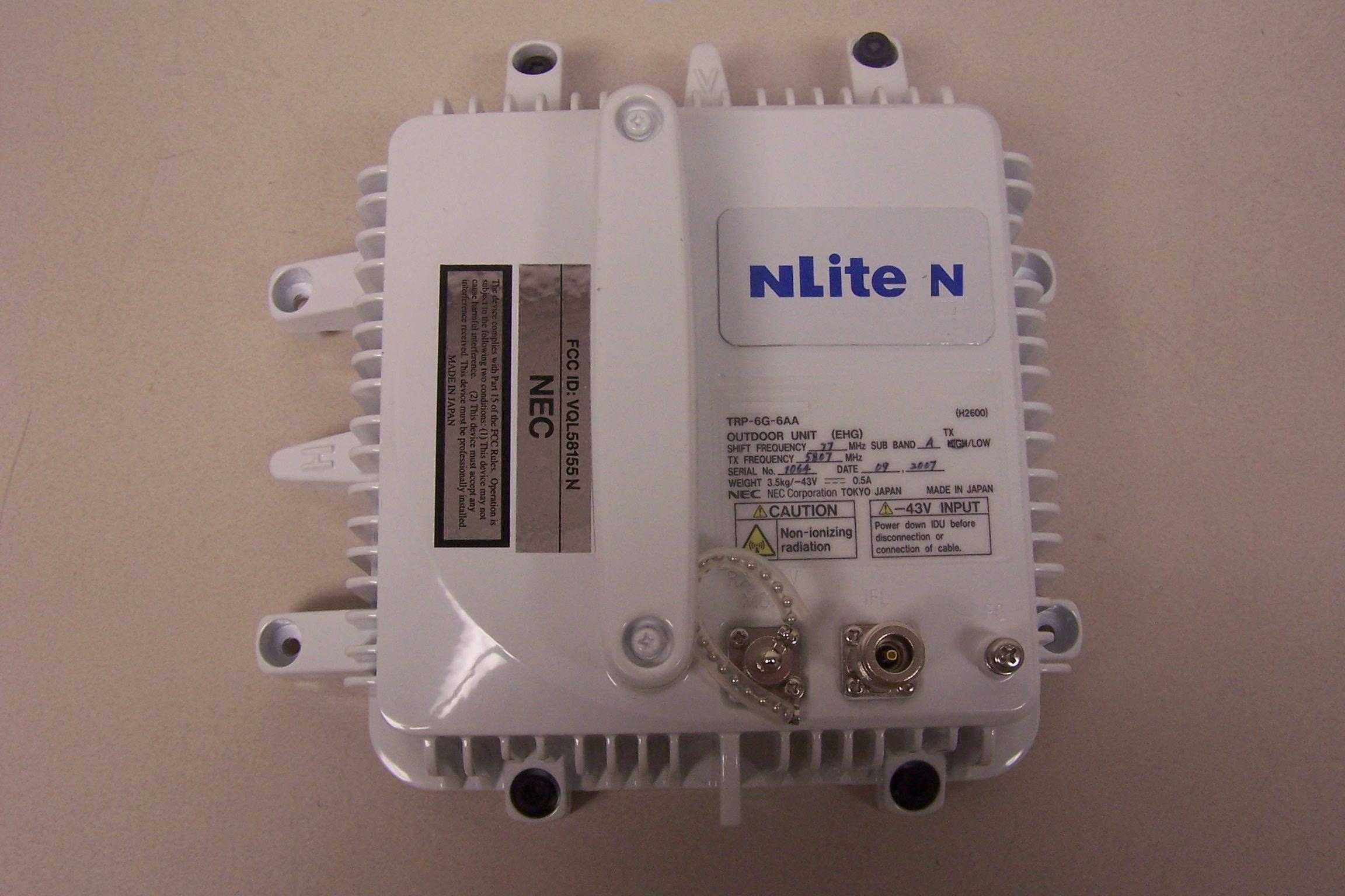
VQL58155N
Apr 08, 2010NLite N 5.8 GHz Digital Microwave Radio
Equipment Class
DTS - Digital Transmission System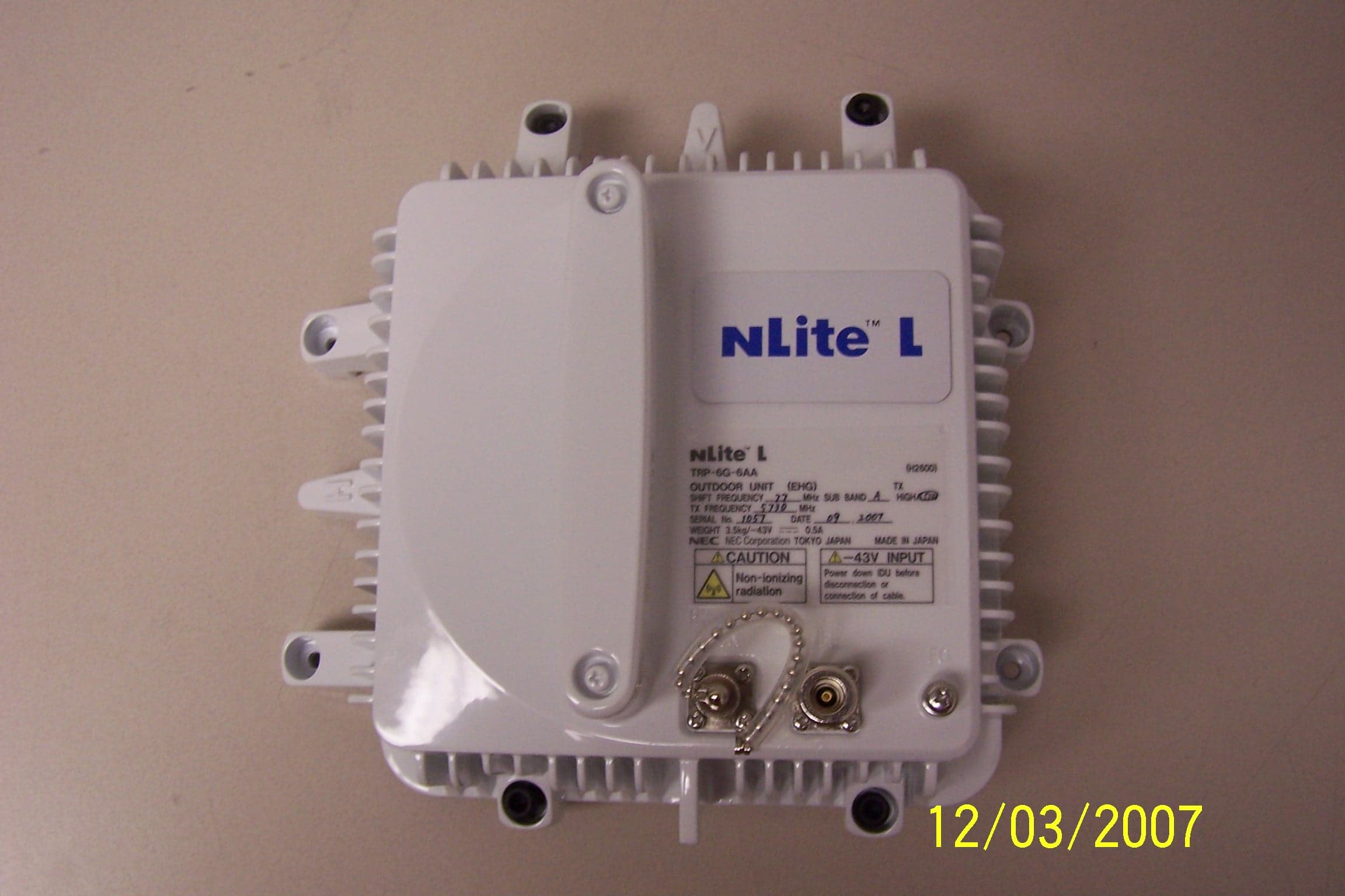
VQL5845
Feb 20, 20085.8 GHz Unlicensed Digital Microwave Radio
Equipment Class
DTS - Digital Transmission System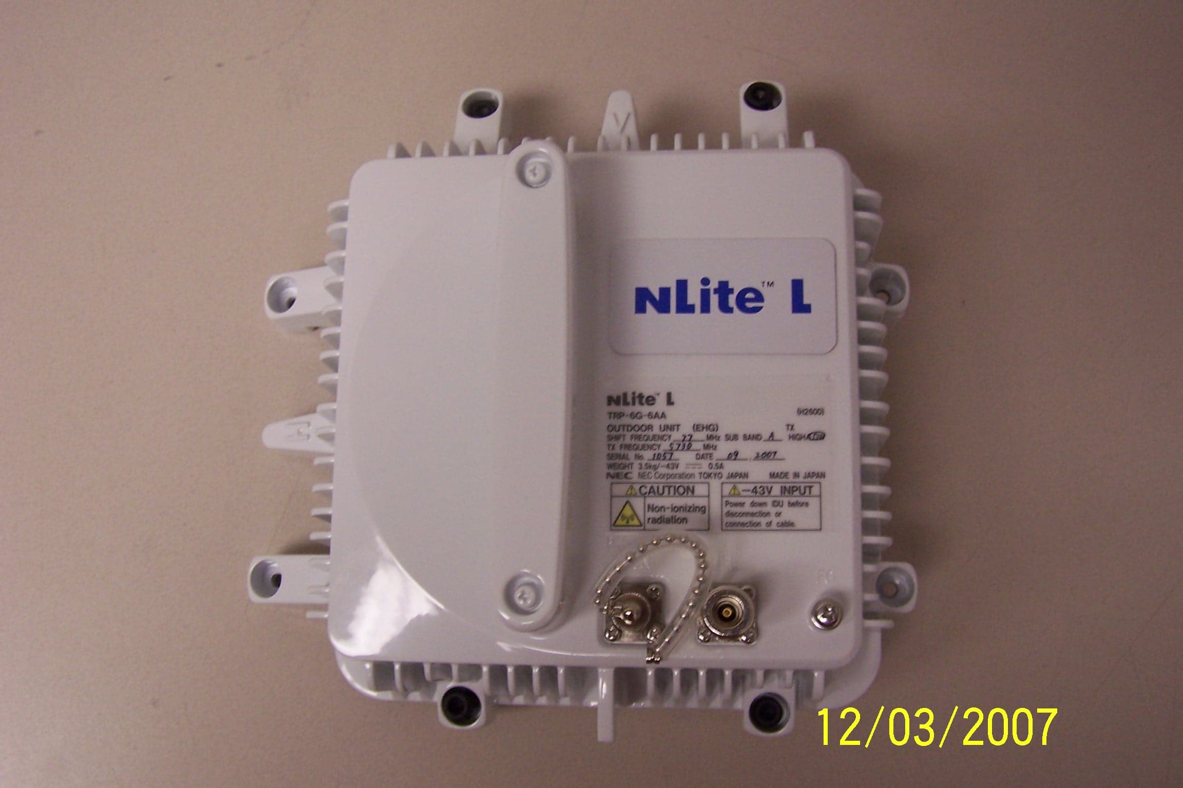
VQL5808
Feb 20, 2008Unlicensed 5.8 GHz Point to Point Microwave Radio
Equipment Class
DTS - Digital Transmission System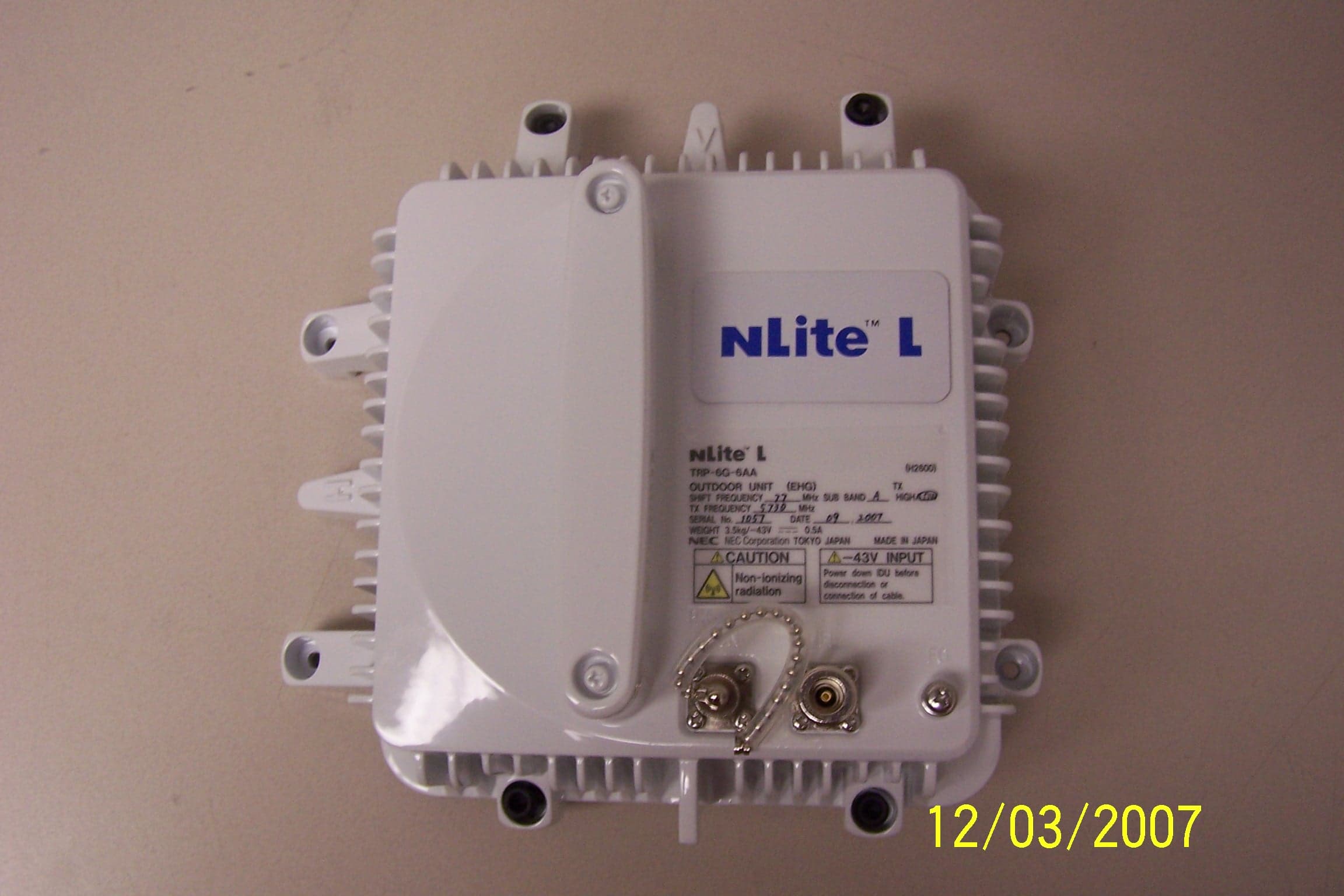
VQL5816
Feb 20, 20085.8 GHz Unlicensed Digital Microwave Radio
Equipment Class
DTS - Digital Transmission System